We know that the conductor with a current placed in a magnetic field comes into motion. This is due to the phenomenon of magnetic induction. There is another very important phenomenon, in a certain sense, the reverse of the phenomenon of magnetic induction: when moving a closed conductor in a magnetic field, an electric current appears in it . This phenomenon is called electromagnetic induction.
Take the conductor, the ends of which are closed on the galvanometer (the device for detecting small electrical currents, you can use a microammeter), and a field of magnet (Figure 1) will quickly cross this conductor. At the same time, we note that the shooter's arrow will rejoint at the moment when the conductor crosses the magnetic field. Consequently, the conductor at this point will pass electric current.
Picture 1. With a quick crossing the conductor of magnetic silest lines Electric current occurs in the conductor.
We now cross the magnetic field of the conductor in the opposite direction. The galvanometer arrow will re-deviate again, but already in the opposite direction. This suggests that electric current passed through the conductor, but in the opposite direction.
From here we can conclude that when crossing the conductor magnetic field In the conductor arises EMF., the direction of which depends on the direction of traffic of the conductor. This EMF is called Inducted EMF. or EMF induction , that is, the guidance of EMF in the explorer and there is nothing but electromagnetic induction phenomenon (Do not mix with magnetic induction!).
Attaching the induction emf when driving a conductor in a magnetic field is explained as follows. When the conductor moves, the free electrons in it are moving with it. When studying magnetic induction, we learned that electric chargesmoving in a magnetic field acting in the direction perpendicular to the direction of the magnetic flux. Therefore, when moving electrons, together with a conductor crossing magnetic power lines, the forces will be operated on electrons, forcing them to move along the conductor, which leads to the emergence electric current in him.
The phenomenon of electromagnetic induction is of great importance in electrical and radio engineering, so we will focus on it several more.
Let's try moving the conductor in a magnetic field at different speeds. At the same time, we note that the arrow of the galvanometer will deviate the more, the faster our conductor crosses the magnetic field. With a very slow movement, the conductor in it does not occur at all or, more precisely, the current will be so small that our galvanometer is not able to detect it.
Next, we draw attention to the fact that, by moving the conductor into the space between the poles of the magnet, we thus increase the number of magnetic power lines covered by a closed circuit of the conductor, and when the conductor is reversed, we reduce the number of these lines, or, in other words, in the first case the magnetic The stream covered by our closed circuit increases, and in the second case decreases. From this point of view, the occurrence of induction current in a closed conductive circuit, we can explain as a result of changing the magnitude of the magnetic flux inside the contour; Large or smaller deviations of the arrows at different speeds of the conductor indicate that the induction EMF depends on the rate of change of magnetic flux inside the contour.
For rapid increase (or descending) Magnetic flux inside the circuit in it is guided big EMF induction, and when slow increase (or descending) - malaya.
On the principle of electrodynamic microphones, pickups, transformers, electrical measuring devices, electric current generators, etc.
The cause of the current in the closed circuit is an electromotive force excited by a third-party force. If the circuit 2 in fig. 8.1 Open, the galvanometer will show no induction current. However, E.D.S. Electromagnetic induction in circuit 2 When a magnetic flux change through its cross section will still arise. Faraday's experiments allowed him to formulate electromagnetic induction law:
With any change in the magnetic flux covering the contour, E.D.S. appears in it. electromagnetic induction, the value of which is proportional to the rate of change of magnetic flux:
 (8.1)
(8.1)
where the minus sign corresponds to the ruler of Lenza: E.D.S. Induction counteracts the reason that caused this reason.
Let a constant magnetic field created in the laboratory reference system. Let the movement of the circuit with a constant speed leads to a change in the magnetic flux through the cross section covered by the contour. The observer in the laboratory reference system sees the reason for the occurrence of a third-party force in the action of the Lorentz force on the current carriers in the circuit (see Fig. 8.2).
Express EDs Electromagnetic induction in contour:
![]()
where - the tension of the field of third-party forces,
![]()
and - the Lorentz power acting on the free charge in the circuit element, which moves at speed.
From here we get an expression EDs electromagnetic induction for observer in the laboratory reference system:
![]() (8.2)
(8.2)
We take into account the vector identity:
and rewrite expression (8.2):
![]() (8.3)
(8.3)
The contour element displacement vector during the time is equal. Changing the vector of the circuit cross section during the time will be ![]() . Changing the magnetic flux through the cross section covered by the contour, in time will be
. Changing the magnetic flux through the cross section covered by the contour, in time will be
![]() . (8.4)
. (8.4)
Comparing (8.3) and (8.4), we obtain the formula for the law of electromagnetic induction:
(8.1)
Let us turn into the reference system moving along with the contour. In this system, the contour is fixed, and explain the emergence of EDS. Electromagnetic induction due to the action of the Lorentz power is impossible. The observer in the movable reference system binds the appearance of EDS. With the advent of vortex electric field When moving from the laboratory system to the movable reference system.
Output: Electric field, like magnetic, shows relative properties (varies) when switching from one reference system to another.
The tension of the vortex electric field serves as the field strength of third-party strength in the movable reference system :. E.D.S. as scalar value, does not depend on the selection of the reference system. In a moving system
![]()
Comparing the last expression with (8.2) and considering the arbitrariness of the contour selection, we obtain an expression for the tension of the vortex electric field through the induction of the magnetic field and the speed of the circuit:
When the induction current flows in the circuit, Jowle is highlighted. This energy is equal to the operation of the mechanical forces leading to the contour in motion.
Ballistic Method of Measurement Induction Magnetic Field Developed A.G. Counters (learn independently).
Let the contour formed not with one turn, and forms a solenoid from turns. Since the coils are connected consistently, then ED, excited in separate turns, consistent. Full EDs induction in the coil
 (8.6)
(8.6)
where - flow or full magnetic reel flow,

and - magnetic flow of a circuit; If all these streams are the same, then
Induction currents can be excited not only in wire circuits, but also in solid massive conductors. Then they are called induction currents or fouco currents. These currents can achieve large values, as solid conductors have a small resistance. In accordance with the Rule of Lenz, induction currents counteract the reason that caused them. Therefore, when driving massive conductors in a strong magnetic field, these conductors are experiencing strong braking. Braking is caused by the force acting on the currents of Foucault by the magnetic field.
In the technique of Toki Foucault can have a useful effect. For example, in the measuring devices on the arrow axis, a metal plate is fixed, which is introduced into the gap between the poles of the magnet. When the plate moves, induction currents arise in it, causing the braking of the entire system. Braking does not prevent the arrows to the equilibrium.
The thermal effect of Foucault currents are used in induction furnaces. The furnace is formed by the coil, which is powered by a high-frequency current of great strength. Metals can be melted and obtain chemically pure samples.
Before the appearance of ferrites, ferromagnetic electromagnet cores were made from plates. This made it possible to reduce the intensity of Foucault currents in cores and, accordingly, the loss of energy to heat the cores during their marking.
As the frequency increases, the alternating current is increasingly concentrated in the surface layer of the conductor ( skin effect). Variables Toki. Fouco is directed so that weaken the current inside the wire, but reinforce the surface. The surface effect leading to the current to the surface layer of the conductor allows the use of hollow tubular conductors in high-frequency circuits.
Another technical use of the phenomenon of electromagnetic induction serve aC generators(Examine yourself).
Topic:Electromagnetic induction
Lesson:Movement of the conductor in a magnetic field
In order to establish the nature of the strength in the conductor, which moves in the magnetic field, will carry out an experiment. Suppose that in a vertical homogeneous magnetic field with induction () is located horizontal conductor length ( l.), which moves at a constant speed () perpendicular to the magnetic field induction vector. If a sensitive voltmeter is connected to the ends of this conductor, we will see that it will show the presence of the potential difference at the ends of this conductor. We find out where it is taken from this tension. In this case, there is no contour and there is no changing magnetic field, so we cannot say that the movement of electrons in the conductor arose as a result of the appearance of a vortex electric field. When the conductor moves, as a single whole (Fig. 1), at the charges of the conductor and in positive ions that are in the nodes crystal lattice, and in free electrons there is a speed of directional movement.
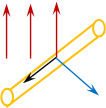
Fig. one
Lorentz's power from the magnetic field will act on these charges. According to the rule of the "left hand": four fingers located in the direction of movement, the palm is deployed so that the vector of magnetic induction is in the back side, then the thumb indicates the effect of Lorentz's power on positive charges.
The Lorentz power, acting on charges, is equal to the product of the charge module that it transfers multiplied by the magnetic induction module, the speed and sine of the angle between the magnetic induction vector and the speed vector.
This force will work on the transfer of electrons for small distances along the conductor.
Then the full work of Lorentz's strength along the conductor will be determined by the power of Lorenz multiplied by the length of the conductor.
The ratio of the work of a third-party force to move the charge to the magnitude of the charged charge by definition of the EDC.
![]() (4)
(4)
So, the nature of the emergence of EDC induction is the work of the power of Lorentz. However, formula 10.4. It can be obtained formally, based on the definition of the EMF electromagnetic induction, when the conductor moves in a magnetic field, crossing the magnetic induction line, overlapping a single platform that can be defined as a product of the conductor length to move, which can be expressed through the speed and time of movement. EMF induction in the module is equal to the ratio of changes in the magnetic flux by time.
Magnetic induction module is permanent, but the area is changed, which covers the conductor.
(6)
After substitution, expressions in formula 10.5. And we get reductions:
Lorentz's power, acting along the conductor, due to which the redistribution of charges is only one component of the forces. There is also a second component that occurs precisely as a result of the movement of charges. If the electrons begin to navigate through the conductor, and the conductor is in a magnetic field, then the Lorentz power begins to act, and it will be directed against the movement of the conductor speed. Thus, the summing power of Lorentz will be zero.
The resulting expression for EMF induction arising when the conductor moves in the magnetic field can be obtained and formally, based on the definition. EMF induction is equal to the rate of change of magnetic flux per unit of time taken with a minus sign.
![]()
![]()
When a fixed conductor is in a changing magnetic field and when the conductor itself moves in a constant magnetic field, a phenomenon occurs electromagneticinduction. And in fact, and in another case, EMF induction occurs. However, the nature of this power is different.
- Kasyanov V.A., Physics 11 Kl.: Education. For general education. institutions. - 4th ed., Stereotype. - M.: Drop, 2004. - 416 p.: Il., 8 liters. color incl.
- Tikhomirova S.A., Yarovsky B.M., Physics 11. - M.: Mnemozin.
- Gentendestein L.E., Dick Yu.I., Physics 11. - M.: Mnemozin.
- Fizportal.ru ().
- Eduspb.com ().
- Cool physics ().
Homework
- Kasyanov V.A., Physics 11 Kl.: Education. For general education. institutions. - 4th ed., Stereotype. - M.: Drop, 2004. - 416 p.: Il., 8 liters. color incl., Art. 115, s. 1, 3, 4, art. 133, s. four.
- A vertical metal rod 50 cm long moves horizontally at a speed of 3 m / s in a homogeneous magnetic field with an induction of 0.15 T.. The induction lines of the magnetic field are directed horizontally at right angles to the direction of the rod speed vector. What is equal to EDC induction in the rod?
- What is the minimum speed, it is necessary to move in a homogeneous magnetic field with a magnetic induction of 50 MTL rod 2 m long, so that the EDC induction appears in the rod 0.6 V?
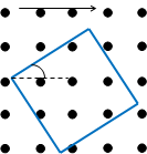
- * Square made of wire with a length of 2 m moves in a homogeneous magnetic field with an induction of 0.3 TL (Fig. 2). What is the EMF induction in each of the sides of the square? General EMF induction in the circuit? υ \u003d 5 m / s, α \u003d 30 °.