Lecture 5. Electric field strength
Concept electric field It turned out to be fruitful because it was possible to introduce quantitative characteristics that allow us to solve specific physical problems. These primarily include the tensions and potential of the electric field.
Experimental student studies should show that the tension can actually be measured and that this value really characterizes the electric field. Relatively new for schoolchildren is the same device, an electrostatic dynamometer, with appropriate calibration can be used as a meter and strength, and voltage. However, this does not mean that any electrostatic value can be measured by this device: none of the calibration of the electrostatic dynamometer will be able to obtain a device measuring, say, the potential of the electric field.
It is fundamentally important an experimental substantiation of the principle of superposition of electric fields. Such a justification could be carried out already with the introduction of the concept of the electric field, but it is preferable to do this when students will be familiar with the concept of tension.
5.1. Electric field strength. The power characteristic of the electric field is the electric field voltage vector E. equal to the ratio of the vector of the force acting at this point point on a test positive charge, to the magnitude of this charge:
The tension in the SI units is expressed in Newton to the pendant (N / CL).
5.2. Electric field tension point charge. In many tasks of electrostatic, the size of charged bodies compared to distances to observation points can be neglected. In such cases, they talk about point charges. It is clear that in fact no point charges or charged points in nature exists - it is just a comfortable abstraction.
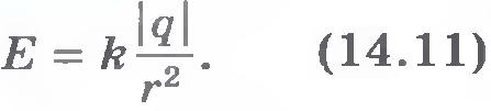
The law of Coulon, as you know, is just for point charges. Directly from the Culon law it follows that point charge electric field voltage vector module Q.:
![]() (5.2)
(5.2)
where R. - distance to the observation point, q. - Trial positive charge.
5.3. Power lines electrostatic field. Faraday, which introduced the concept of an electric field, saw the charges surrounded by fields. It was the lines along which the forces act on the test charge on the side of the field. Power lines electrostatic fields are often called voltage linesbecause The voltage vector of the electric field at any point of such a line is tied to it. Instead of a trial charge for building silest lines It is more convenient to use an electric dipole.

Entering a positive test charge on the thread into the electric field, by its deviation from the equilibrium position, we define the direction of the field strength. Remove the charge and instead of it at the same point dipole. In this case, it is discovered that he turned his positive pole in the direction of the tension of the electric field. Using the dipole, it is not difficult to experimentally prove that the electric field can be characterized by power lines, i.e. Such lines, at each point of which the field strength is tangent to them.
To do this, create an arbitrary electric field, introduce a dipole into it and we note the position of its positive and negative poles. Move the dipole so that it, for example, a negative pole coincided with a point in which there was positive. Repeating this operation repeating this operation, we obtain a set of points. By connecting these points with a smooth line, we obtain the power line of the extended electrostatic field.
Experience shows that only one power line passes through each field. If it were not so, then at the point of intersection of the two power lines of one field, different forces would be operated on the charge.
Repeating the above-described steps, we construct a family of power lines so that their initial points are on the surface of the charged body at equal distances from each other. We discover that the power lines are located with different dense. We enter the trial charge for the threads in the area with the maximum and minimum thickness of the lines and find that in these areas the electric field the electric field is maximal and minimal.
The power lines are condensed near charges, i.e. Where the electric field strength vector module is larger. So, the thickness of the power lines is determined by the field strength. A family of power lines in principle can fully characterize the electric field.
The experienced experiments show that the power lines begin or end on charges, go into infinity or go out of it. In the electrostatic field there are no closed power lines.
5.4. The principle of superposition of the tensions of electrostatic fields. Of the principle of the superposition of fields, it follows that the force acting on the test charge from other charges is equal to the geometric sum of all the forces acting on the charge separately. But if so, then the tensions of electric fields, equal to the relationship of the forces to the magnitude of the test charge, are folded like the forces.
Thus, for electric fields fair superposition principle In the following wording: the tension of the resulting electric field is a geometric (vector) sum of the intensities of fields created by individual charges:
E. = E. 1 + E. 2 + E. 3 + … (5.3)
The use of the principle of superposition for tensions makes it possible to significantly facilitate the solution of many tasks of electrostatics.
5.5. Electric field strength vector stream. Imagine a point positive charge Q.located in the center of the spherical surface 1
radius r.. At the points of this surface, the tension of the electric field  Since Square
surfaces of the sphere S. = 4r. 2, then its work on the tension of the electric field does not depend on anything other than charge:
 (5.4)
(5.4)
therefore, characterizes the electric field as a whole. This value was named electric field strength vector flow.
Stroy stream through concentric spherical surfaces 1 and 2 same. Since it characterizes the charge field as a whole, it is necessary that it remains the same for an arbitrary closed surface 3 . But for it, the voltage vector is no longer normal to the surface element. So to determine the flow of the vector E. Through the surface element instead of the area of \u200b\u200bthis item, it is necessary to take the area of \u200b\u200bits projection on the plane perpendicular to the vector E. . We consider the flow to be considered positive if the voltage vector comes out of the closed surface, and negative if it enters it. If the charge is outside the closed surface 4 , The strength flow through it is zero. The fact is that the flow of the module internally entering the region is equal to the output.
5.6. Gaussian theorem. Mentally move the charge from the center of the spherical surface to anywhere inside it. Obviously, the flow vector strength of the electric field will not change from this, because, by the very definition, it is the same for any closed surface surrounding the charge. There are not alone inside this surface, but somewhat in the general case of various charges. On the principle of superposition, the electric fields of these charges do not affect each other, it means that the streams created by each charge separately remain unchanged. The resulting flow is obviously equal to the amount of streams from all charges.
That's what it is theorem Gaussa: The strength of the voltage vector through an arbitrary closed surface is equal to the algebraic amount of charges located inside this surface, divided by electric constant:
 (5.5)
(5.5)
If the algebraic amount of charges inside the closed surface is zero, then the strength of the electric field strength through this surface is also zero. This is understandable, since positive flows inside the surface create a positive stream, and the negative - the negative module is equal to it.
5.7. Surface density charge.If the conductive body inform the charge, it will be distributed over its surface. In the general case, different charges will be on the surface sections of the same area. The ratio of charge Q. To Surface Square S.on which it is distributed, called surface density charge
The surface density of the charge is expressed in the coulutes per square meter (CL / m 2).
5.8. The tension of the electrical field of the charged ball. Using the Gauss theorem, it is not difficult to determine the tension of the electric field created by the charged conductive ball. Indeed, if on the surface of the sphere by the radius r. > R., the center of which coincides with the center of the ball, is evenly distributed charge Q., then the flow of the vector E. through a spherical surface with a radius r.According to the Gauss Theorem, is:
Hence the tension of the electric field at a distance of R from the center of the charged sphere is equal
 (5.7)
(5.7)
Comparing (5.7) C (5.2), we conclude that the voltage of the electric field of the charged ball is equal to the tension of the same point charge located in the center of the ball. 
5.9. The tension of the electrical field of the charged plane. Consider an infinite plane charged uniformly with the surface density of the charge. The electrical field of such a surface is homogeneously, and the power lines are perpendicular to the surface. To find the field strength, we use the Gauss theorem. To do this, we construct a closed cylindrical surface, the axis of which is parallel to the power lines of the field, and the base ground S. Are on different sides of the surface. The strength of the voltage through the side surface of the cylinder is zero, because The power lines do not intersect. Therefore, the full stream of tension through the selected surface is equal to the amount of flow through the base of the cylinder: N. = 2 ES.. Full charge inside the cylinder is equal Q. = S.. According to the Gauss Theorem,  Hence the tension of the electric field
So, the tension of the electric field of the charged plane is equal to the surface density of the charge, divided into doubled the electrical constant.
5.10. The voltage of the electric field of the variestly charged parallel planes. Let some plane charge evenly with a charge density. By parallel to this plane, we will place the second, with the same charge density of the opposite sign. Find the voltage of the electric field in this case.
Each plane creates a voltage field E " \u003d / (2 0). According to the principle of superposition, the tension of the resulting electric field is equal to the sum of the tension of these fields. Since there are the same direction between the field tension planes, then the resulting tension E. = 2E ":
Therefore, the tension of the electric field between parallel planes, carriage equal in the module, the varied charges is equal to the surface density of the charge of one of the planes divided into electrical constant. Outside the planes, voltage vectors are directed oppositely and, since their modules are equal, the field is generally absent. Please note that it does not matter whether electricity plane is carried out or not.
Problem. Is there a quantitative assessment of the voltage of the electric field created by charges on electrified bodies available in an accessible experiment? 
The task. Using an electrostatic dynamometer, develop a technique for introducing the concept of electric field strengths and offer an instrument for measuring tension.
Execution option. Check the ball report to definitely positive. On the test ball of the electrostatic dynamometer (see Study 3.4) also apply some charge. Enter the dynamometer into the electrical field of the charged ball and expand so that its readings become maximum. This means that the test ball of the electrostatic dynamometer deviates to the same side, where the force acting on it from the electrical field is directed.
Touch the trial ball with the same uncharged ball and remove it: the test charge decreases twice, the dynamometer readings for the same distance to the observation point are also reduced twice.
Repeating experience with different charges, make sure the strength relationship f.trial q., To the magnitude of this charge, at this point of the field remains constant, and when moving from one point to another, generally speaking, changes. It means that this relationship can characterize the electric field. It got a name electric field strength. The scale of the electrostatic dynamometer you used to measure the power of electrostatic interaction can be separated in units of tension. Then it is permissible to consider this device tension meter electric field. The graduation is easy to implement in the N / CL units, if you pre-measure the value of the test charge (see study 3.6).
Students must understand how the same device has become a power meter into the tension meter.
Research 5.2. The dependence of the power supply voltage from the radius of the charged ball
The task.Develop a demonstration experiment, which can serve as a justification for the equity Gauss theorem for electrostatic fields.
Execution option.
Charge standing on a dielectric stand. A small spending ball. To it move the electric field strength meter, the trial ball of which carries the same in the charge sign as a charge that creates the studied field. Remember the deviation of the meter arrows.
The first ball with a charge to lower the second conductive ball in the cavity of a significantly larger diameter mounted on a dielectric stand. Bind this second ball to the trial ball of tension meter. It turns out that when the center of the second ball coincides with the point in which the center of the first ball was located, the arrow of the meter deflects on the initial number of divisions.
From here it follows that, regardless of the radius of the charged ball at the same distance from its center, the voltage of the electric field is the same. Thus, the Gauss Theorem received confirmation in the demonstration experiment.
It is clear that the Gaussian Theorem is general and, strictly speaking, does not need substantiations like the considered here. BUT B. didactic purposes Such a justification is absolutely necessary because it contributes to the consciousness of students of the inextricable communication of physical theory with objective reality.
Study 5.3. Superposition of electric fields
Information.To ensure the justice of the principle of the superposition of electric fields, you need to be able to determine not only the modules of forces acting on charges, but also their directions. Do this with an electrostatic dynamometer uncomfortable. In addition, it does not allow graphically to depict the strength vector. If on the threads to hang a lightly charged body, then the force acting on it in electric field, It can be estimated to deviate the body from the equilibrium position. But to measure this deviation, it will not be possible to use the ruler: its approach to the charged body causes a change in its position. To eliminate this difficulty, you can integrate the charged body on the horizontal plane. 
The task.Develop and implement an experiment proving the justice of the principle of superposition of electric fields.
Execution option. To the glass cylinder of a small light bulb stick a thin thread with a slightly conductive ball of a small radius at the end. Apply a trial charge to the ball. Light bulb fasten over a sheet of paper and turn it on. On a sheet of paper number 0 Mark the position of the shade from the ball located in the equilibrium position. Approoming to the trial charge charge Q. 1 and digit 1 Mark the position of the shadow of the rejected ball on the sheet. Remove the charge Q. 1 and instead of it near a trial ball position the charge Q. 2. At the same time, the shadow from the ball will take a new position 2 .
Return the charge Q. 1 in the initial position. Now the trial ball is in the field at once two charges and deviates from the equilibrium position so that its shadow occupies the position 3 . Analyze the result of the experiment. Obviously, when the ball shifts from the equilibrium position, its shadow is shifted by the amount proportional to the power acting on the ball in the new equilibrium position (see Study 3.5). With small deviations of the trial ball, this force can be considered equal to the power acting on the ball in the initial position. Length of segments connecting point 0 With dots 1 , 2 and 3 proportional to the modules of the corresponding forces. By connecting the specified vectors, you will find that the vector of the resultant forces acting on a test charge is approximately equal to the sum of the vectors of the forces acting on it from each charge separately. It is clear that accurate measurements made with more perfect devices, instead of approximated will give an accurate equality.
Amazing the unity of nature: the forces created by electric fields are folded in the same way as mechanical! But if so, then the tensions of electric fields, equal to the relationship of the forces to the magnitude of the test charge, are folded like the forces. Leaving the balls immobile, change their charges in the same number of times (see paragraph 2.6). At the same time, you will find that the direction of tension of the resulting field remains unchanged.
Thus, the principle of superposition of electrostatic fields is experimentally justified.
Study 5.4. Demonstration of the principle of voltage superposition
Problem. The individual experience made as a result of the previous study does not make sure that the principle of the superposition of the voltages of electrostatic fields in the entire class is directly in the lesson. How to solve this problem?
The task. Given the capabilities of the codecope, develop a demonstration version of the experiment, justifying the justice of the principle of the superposition, and the methodology for conducting it in the lesson.
Execution option. From the thick aluminum wire in the isolation, bypass a special tripod a height of about 30 cm and put it on the codoscope condenser. To the upper end of the tripod, tie the end of a thin nylon thread with a length of about 20 cm. At the bottom end of the thread, fasten the ball with a diameter of about 3 mm from thin aluminum foil. On the codoscope condenser on the racks of 10 cm high, made of polyethylene tubes, put foam balls with a diameter of 15-20 mm, wrapped in thin foil. The bases of racks are better made from a transparent plexiglass.
Remove the racks from the condenser with the balls, turn on the reference of the codec and on the chalkboard. Get the image of a trial ball hanging on the thread. Single charges charge the test ball and two balls on the racks. On the chalk board, mark the position of the trial ball. Put one of the charged balls on the condenser, mark its position and position of the trial ball. Remove the first charged ball and in an arbitrary place. Put the second, noting the new position of the trial ball on the board. Return the first ball in the original position, mark the resulting position of the trial ball, chalk on the board. Draw the corresponding vector forces and offer students to conclude from demonstrated experience.
Study 5.5. Density charge on the surface of the conductor
The task.Prove that the density of the charge on the surface of the conductor, generally speaking, is different.
Execution option. Charge a cylindrical media conductor with edxcine and conical deepening on an insulating stand. Trial ball on an insulating handle, pre-grounded, tap the cylindrical surface of the conductor and place it inside the hollow ball connected with the electrometer. If the angle of deflection of the arrow is small, repeat the charge of the charge several times. Remember the electrometer readings, discharge it and a trial ball. Try to remove the charge from the conical recess in the surface of the conductor, and you will make sure that it is practically absent there. Repeat the experience, touching the trial ball now the surface points located on the edge of the conductor. In this case, the angle of deviation of the arrow of the electrometer will be much larger than in the first experiment. Since near the eldest, the trial ball is charged to a greater value, then in this area the density of the charge distribution over the surface of the conductor is greater.
Charge a metal disk fixed for an insulating handle in a tripod. After experiments, similar to those described, show that the charge density at all points of the flat surface of the disk away from its edge is the same, and on the edge increases.
The task. Put the experience showing that the voltage of the electric field near the charged conductor is determined by the surface density of the charge.
Execution option. Near the conductor of a complex form, there is a electrostatic dynamometer and move it so that the distance to the surface of the conductor remains constant, and the force acted on the dynamometer ball on the normal surface. Experience should show that there, where on the surface of the conductor, the charge density is greater, near this surface is larger than the electric field strength (see Study 5.5). Analyze the results obtained and make the appropriate conclusions. 
Study 5.7. Electric field near charged planes
The task. Direct experiment confirm that the uniformly charged plane gives an electric field on both sides of it, and two parallel planes that carry equal charges of opposite characters create an electric field only in the area between them.
Execution option.On the threads in susceptible two of the same wrapped aluminum foil balls so that they touch the metal disk from the opposite sides. Charge the disk from a piezoelectric or other source. At the same time, the balls will depart from the disk at equal distances, indicating that the electric field exists on both sides of the charged disk.
 Exactly the same disk charge equal to the module and opposite by the sign of the charge. Gradually bring the second disk to the first so that they remain parallel. You will notice that the deviation of the ball located outside the disks is reduced, and between the discs - increases. Finally, the first ball touches the disk, showing that the field outside the disks has almost disappeared, and the second ball is deflected by an angle, about two times higher than the original.
Study 5.8. Exact confirmation of the law of Kulon
Information.
On the dielectric rack, secure the metal ball and conclude it between two conductive semisers, one of which has a hole. Through the hole of the conductor on an isolated thread. Connect the balloon with semisers. Charge hemispheres. For the thread remove the conductor. Outping a ball and hemispheres, divertoles to the soles, discharge them, and connect a sensitive electron to the ball: you will not find any charge on the ball. So, the experiment shows once again that there is no charge on the conductor inside the other conductor.
This is true because the law of Kulon is fair. Indeed, inside the conductive uniformly charged sphere, choose an arbitrary point BUT and vertical cones cut down on the platform S. 1 I. S. 2. From geometry it is known that ![]() But these sites have charges proportional to their values: small sites create at the point BUT Tension fields
But these sites have charges proportional to their values: small sites create at the point BUT Tension fields ![]() and whose attitudes
and whose attitudes
So, since the tensions of the fields created by any similar pairs of platforms on the sphere are equal to the module and the oppositely directed, the resulting voltage of the field created at the point BUT The entire charged sphere should be zero.
This shows the experiment. If at the experience, at least a weak charge on the inner ball was found, it would be an incorrect formula for the intensity of the point charge field (5.2) and, therefore, in the law of the coulon (3.1), the power of interaction between charges would not be inversely proportional to the square of the distance between them . Since the charge can be measured with a much higher accuracy than the force of interaction between charges, and from the Culon law it follows that the field inside the body is missing regardless of its shape, the experiment considered correctly proves the justice of the Culon law than the previously described experiments. 
The task.Develop and put an available version of the experiment considered, with maximum persuasiveness showing that there is no electric field inside the charged hollow conductor.
Execution option.To detect an electric field, you can use the phenomenon of electrostatic induction. We introduce two contacting conductive bodies on the handles in the field. They will receive the redistribution of charges. Without removing from the field, disconnect these bodies - they will remain the charges of opposite characters. These charges can be measured by an electrometer outside the field under study.
The experiment can be delivered so. On a dielectric stand, secure the hollow metal ball. A conductor in good insulation connect it with one of the conductor of the electrophore machine. To the ball bring the second conductor and bring the machine into action. At the same time there will be powerful spark discharges up to 10 cm long. Gently, enter the same metal plates on the handles from the plexiglass. Put the plates in contact, then disconnect, gently get out of the bowl of the ball and take turns into the ball of the electroometer. You will find that there is no charge on the plates! It means that there is no electric field inside the conductive ball, despite the fact that the ball as a whole carries a significant charge, which is reported to it by the operating electrophore machine. Repeat the experience, touched by a test ball from the inside to the metal of the charged ball, - you will not find any charge again. Thus, the entire electrical charge is concentrated on the surface of the conductive body. This result is explained by the fact that the law of Kulon is fair. In turn, this experimental fact with high accuracy confirms the justice of the Culon law.
Questions for self-control
1. What is the essence of the method of introducing and forming the concept of electric field strength?
2. Compare the method of constructing power lines by dipole with the method of visualizing the electrostatic field with a small powder suspended in a liquid dielectric.
3. Outline the demonstration methodology at the lesson of the principle of superposition of electrostatic fields.
4. What experiment can be confirmed by the justice of the Gauss theorem?
5. How dependes the density of the charge and the voltage of the electric field from the shape of the conductor?
6. Offer a demonstration experience, directly showing the dependence of the charge density from the conductor area.
7. What is the didactic value of experience with the detection of an electric field near one and two parallel charged conductive plates?
8. Do I need to consider the method of accurate confirmation of the Culon law?
Literature
Butikov E.I., Kondratyev A.S. Physics: studies. manual: in 3-kN. Kn. 2. Electrodynamics. Optics. - M.: Fizmatlit, 2004.
Demonstration experiment in physics in high school grades: T. 2. Electricity. Optics. Atom physics: ed. A.A. Pokrovsky. - M.: Enlightenment, 1972.
Kabardin O.F., Orlov V.A., Eventer E.E.. Physics: studies. for 10 cl. shk. and cl. with a coal Research. Physics: ed. A.A.pinsky. - M.: Enlightenment, 1997.
Educational equipment for the Cabinets of physics of general education institutions: ed. G.G.Nikorov. - M.: Drop, 2005. (CM. Also "Physics" ("PS") No. 10/2005; No. 4/2007.)
We define the tension of the electric field of charged bodies of a simple form: a bowl and plane. About spherical shape They have many bodies in nature and technology: atomic nuclei, rain drops, planets, etc. Flat surfaces are also often found. In addition, a small portion of any surface can be approximately considered flat.
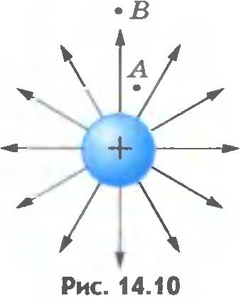
Bowl field. Consider the charged ball with a radius charge is uniformly distributed over the surface of the ball. The power lines of the electric field, as flowing from symmetry considerations, are directed along the continuations of the radius of the ball (Fig. 112).
Please note: the power lines outside the ball are distributed in space in the same way as the power lines of the point charge (Fig. 113). If the patterns of power lines coincide, then we can expect that the field strengths coincide. Therefore, at a distance from the center of the ball, the field strength
determined by the same formula (8.11) as the intensity of the field of a point charge, placed in the center of the sphere:
This result also leads strict calculations.
Inside the conductive ball, the field strength is zero.
Field of plane. Distribution electric charge On the surface of the charged body is characterized by a special value - the surface density of the charge. Surface density of charge is called the ratio of the charge to the surface area, according to which it is distributed. If the charge is uniformly distributed over the surface, the area of \u200b\u200bwhich is 5, then
Name unit surface density Charge
For symmetry considerations, it is obvious that the power lines of the electrical field of an infinite uniformly charged plane are straight, perpendicular planes (Fig. 114). Field infinite plane - a homogeneous field, i.e. in all points of space, regardless of the distance to the flat bone, the field strength is the same. It is determined by the superficial charge density.
To find the dependence of the field strength from the surface density of the charge, you can use a frequently used method in physics based on the knowledge of names physical quantities. The unit of electric field strength has a name A unit of surface density charge
In order to get the right name of the field strength, we must assume that
\u003e\u003e Physics: Electric field power lines. Tension Field of the Charged Bowl
The electric field does not affect the senses. We do not see him.
However, we can get some idea of \u200b\u200bthe field distribution if you draw the field strength vectors at several space points ( fig.14.9.left). The picture will be more visual, if you draw continuous lines regarding which at each point through which they pass, coincide in the direction of tension vectors. These lines are called power lines of the electric field or intensity lines (fig.14.9., on right).
The direction of power lines allows to determine the direction of tension vector at different points of the field, and the thickness (the number of lines per unit area) of the power lines shows where the field strength is greater. So, in Figures 14.10-14.13 Delicate of power lines at points BUTmore than at points IN. Obviously  .
.
It should not be thought that intensity lines exist in reality like stretched elastic threads or cords, as Faradays assumed. Tension lines help only visualize the field distribution in space. They are not more real than meridians and parallels on globe.
However, the power lines can be made visible. If the oblong crystals of the insulator (for example, quinine) mix well in a viscous fluid (for example, in castor oil) and put the charged bodies there, then the crystalline bodies close in the chains along the tension lines.
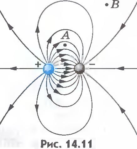
The figures provide examples of tension lines: a positively charged ball (see fig.14.10); Two different charged balls (see fig.14.11); Two charged balls simultaneously (see fig.14.12); two plates whose charges are equal to the module and are opposite by the sign (see fig.14.13). Last example Especially in Figure 14.13 it can be seen that in the space between the plates closer to the middle of the power lines parallel: the electric field here is the same in all points.


Electric field whose tension is the same in all points of space, called uniform. In a limited area of \u200b\u200bspace, the electric field can be considered approximately homogeneous if the field strength within this area changes slightly.
A homogeneous electric field is depicted by parallel lines located at equal distances from each other.
The power lines of the electric field are not closed, they begin on positive charges And ends on negative. The power lines are continuous and do not intersect, since the intersection would mean the absence of a certain direction of the electric field strength at this point.
Field of a charged bowl. Consider now the question of the electrical field of the charged conductive ball by the radius R.. Charge q. Equally distributed over the surface of the ball. The power lines of the electric field, as symmetry follows from considerations, are directed along the continuations of the ball radii ( fig.14.14, A.).

Note! Force The lines outside the ball are distributed in space in the same way as the power lines of the point charge ( fig.14.14, B.). If the patterns of power lines coincide, then we can expect that the field strengths coincide. Therefore, at a distance r\u003e R. From the center of the ball, the field strength is determined by the same formula (14.9) as the intensity of the point charge field placed in the center of the sphere:
The pattern of power lines clearly shows how the electric field strength is directed at various points of space. By changing the lines of lines, you can judge the change in the field strength module when moving from point to point.
???
1. What is called power lines of the electric field?
2. In all cases, the trajectory of the charged particle coincides with the power line?
3. Can the power lines intersect?
4. What is the tension of the field of the charged conductive ball?
G. Y. Mikishev, B.B. Bukhovtsev, N.N.Sotsky, Physics 10
Design of lesson Abstract lesson reference frame presentation lesson accelerative methods interactive technologies Practice Tasks and exercises self-test Workshop, trainings, cases, quests Home tasks Discussion issues Rhetorical questions from students Illustrations Audio, video clips and multimedia Photos, pictures, tables, Schemes of humor, jokes, jokes, Comics Proverbs, sayings, crosswords, quotes Supplements Abstracts Articles Chips for Curious Cheat Sheets Textbooks Basic and Additional Globes Other Terms Improving textbooks and lessons Fixing errors in the textbook Updating fragment in the textbook. Innovation elements in the lesson replacing outdated knowledge new Only for teachers Perfect lessons Calendar Plan for the year Methodical recommendations of the discussion program Integrated lessonsIf you have corrections or suggestions for this lesson,


