Alternating current carries energy. Therefore, the issue of capacity in the chain is extremely important. alternating current.
Let U and I be the instantaneous value of the voltage and the strength of the current on this section of the chain. Take a small time interval DT as small that the voltage and current will not have time to change anything during this time; In other words, the values \u200b\u200bof U and I can be considered permanent during the DT interval.
Let DQ \u003d IDT charge passed through our site (in accordance with the rule selection rule for the current force, the DQ charge is considered positive if it is transferred in a positive direction, and negative otherwise). The electric field of moving charges made the work
da \u003d udq \u003d uidt:
Current Power P is the work ratio electric field By the time for which this
the work perfect: | |||||
Exactly the same formula we received in our time for DC. But in this case, power depends on time, making fluctuations together with current and voltage; Therefore, the value (118) is called an instant power.
Due to the presence of the phase shift, the current and voltage in the site are not required to match the sign (for example, it may happen that the voltage is positive, and the current is negative, or vice versa). Accordingly, the power can be both positive and negative. Consider a little more about both of these cases.
1. Power is positive: p\u003e 0. Voltage and current strength have the same signs. This means that the direction of current coincides with the direction of the electric field of charges forming the current. In this case, the energy of the site increases: it enters this area from the external circuit (for example, the capacitor is charged).
2. Power is negative: P< 0. Напряжение и сила тока имеют разные знаки. Стало быть, ток течёт против поля движущихся зарядов, образующих этот самый ток.
How can this happen? Very simple: electric fieldarising on the site, as if ¾ takes the field of moving charges and ¾ valves the current against this field. In this case, the energy of the site decreases: the site gives energy to the outer chain (for example, the capacitor is discharged).
If you do not quite understand what we just went on, do not worry further there will be concrete examples on which you will see everything.
24.1 Current power via resistor
Let alternating current i \u003d i0 sin! T flows through the resistance resistor R. The voltage on the resistor, as we know, fluctuates in the phase with the current:
U \u003d Ir \u003d i0 R sin! T \u003d u0 sin! T:
Therefore, for instant power we get:
P \u003d ui \u003d u0 i0 sin2! T;
The maximum value of P0 of our power is associated with current and voltage amplitudes
the familiar formulas:
U 2p 0 \u003d u 0 i 0 \u003d i 0 2 R \u003d R 0:
In practice, however, interest is not the maximum, but the average power of the current. This is understandable. Take, for example, the usual light bulb that burns at your home. It flows a current with a frequency of 50 Hz, that is, in a second 50 oscillations of current and voltage force are performed. It is clear that for a sufficiently long time on the light, some average power is distinguished, the value of which is somewhere between 0 and p0. Where exactly?
Look once again carefully in Fig. 1. Do you have an intuitive feeling that the average power corresponds to the ¾ medical of our sinusoids and does it make it therefore p0 \u003d 2?
This feeling is completely true! The way it is. Of course, it is possible to give mathematically strict definition of the average value of the function (as a certain integral) and confirm our guess by direct calculation, but we do not need it. Quite an intuitive understanding of a simple and important fact:
the average value of the sinus (or cosine) square for the period is 1/2: |
|
This fact is illustrated in Figure 122. |
|
y \u003d sin2 x |
|
Fig. 122. The average sinus square value is 1/2 |
|
So, for the average value P of the power of the current on the resistor we have:
U0 I0. | I0 2 R. | U0 2. | ||||||||||

Due to these formulas, so-called existing (or effective) voltage and current values47 are introduced:
U \u003d P. | I \u003d P. | |||||||
Formulas (120) recorded through acting values \u200b\u200bare completely similar to the corresponding DC formulas:
P \u003d u i \u003d i2 r \u003d u 2:
Therefore, if you take the light bulb, connect it first to the source of the constant voltage U, and then to the source of alternating voltage with the same valid value of U, then in both cases the light bulb will burn the same brightly.
The existing values \u200b\u200b(121) are extremely important for practice. It turns out that voltmeters and AC ammeters show valid values \u200b\u200b(so they are arranged). It is also known that the notorious 220 volts from the outlet is the active value of the voltage of household power supply.
24.2 Current power through capacitor
Suppose to the condenser the variable voltage u \u003d u0 sin! T. As we know, the current through the condenser is ahead of phase voltage by \u003d 2:
I \u003d i0 sin! T + | I0 COS! T: |
|||
For instant power we get: | ||||
P \u003d ui \u003d u0 i0 sin! T cos! T \u003d | U0 I0 SIN 2! T; |
|||
P \u003d P0 SIN 2! T: |
||||
Here the designation is introduced P0 \u003d U0 i0 \u003d 2. The chart of dependence (122) instantaneous power on time is represented in Fig.123.
Consider sequentially all four quarters of the period.
1. First quarter, 0< t < T=4. Напряжение положительно и возрастает. Ток положителен (течёт в положительном направлении), конденсатор заряжается. По мере увеличения заряда на конденсаторе сила тока убывает.
Instant power is positive: the condenser accumulates the energy coming from the external chain. This energy occurs due to the work of an external electric field, promoting charges to the condenser.
2. Second quarter, T \u003d 4< t < T=2. Напряжение продолжает оставаться положительным, но идёт на убыль. Ток меняет направление и становится отрицательным: конденсатор разряжается против направления внешнего электрического поля. В конце второй четверти конденсатор полностью разряжен.
Instant power is negative: the condenser gives energy. This energy returns to the chain: it goes to perform the work against the electrical field of the outer chain (the condenser is like ¾ of the charges of the charges in the direction opposite to that in which the external field can move them).
3. Third quarter, t \u003d 2< t < 3T=4. Внешнее электрическое поле меняет направление: напряжение отрицательно и возрастает по модулю. Сила тока отрицательна: идёт зарядка конденсатора в отрицательном направлении.
The situation is completely similar to the first quarter, only voltage and current signs are opposite. Power is positive: the condenser reappears energy.
4. Fourth quarter, 3t \u003d 4< t < T . Напряжение отрицательно и убывает по модулю. Конденсатор разряжается против внешнего поля: сила тока положительна.
Power is negative: the condenser returns energy to the chain. The situation is similar to the second quarter again with replacing the replacement of current and voltage signs on the opposite.
We see that the energy pointed by a capacitor from the external chain during the first quarter of the oscillation period is completely returned to the chain during the second quarter. Then this process is repeated again and again. That is why the average power consumed by the capacitor turns out to be zero.
September 21, 2017.At one time, Edison and Tesla were opponents in the use of electric current In energy. Tesla believed that it is necessary to use alternating current, and Edison - what to apply d.C.. The second scientist had more opportunities, as he was engaged, but Tesla eventually managed to win, as he was simply right.
Introduction
Variable current is much more efficient to use for energy. Let us discuss how the power of the AC is calculated, because alternating current is the power that is transmitted at a distance.
Power calculation
For example, we have an alternating voltage generator that is connected to the load. At the outlet of the generator, between two points on the terminals, the voltage varies on the harmonic, and the load is taken arbitrary: coils, active resistance, condensers, electric motor.
In the load circuit flows current, which changes by harmonic law. Our task is to establish what is equal to the power of the load from the generator. We have a generator. As source data, the entrance direction is represented as a harmonious rule:
The power of the current in the load and, accordingly, in the wires that supply power to the load will change. The frequency of current oscillations will be the same as the frequency of voltage oscillations, but there is also the concept of phase shift in the ranges of current and voltage oscillations:
(I (T) \u003d I (M) COS W T)
Further calculations
Indicators Power will be equal to the work:
P (T) \u003d I (T) U (T)
This law remains fair both for AC with a power that it was necessary to calculate and for permanent.
(I (T) \u003d I (M) COS (WT + J)
AC power with alternating current is calculated using three formulas. The above calculations refer to the main formula that follows from the determination of current and voltage.
If the chain section is homogeneous and you can use the Ohm's law for this section of the chain, it is impossible to use such calculations here, since we are unknown the character of the load.
Determine the result
We will substitute the indicators of the current and voltage into this formula, and here we will come to the aid of the trigonometric formulas:
cOSA COSB \u003d COS (A + B) + COS (A - B) / 2
We use this formula and get the calculation:
P (T) \u003d I (M) U (M) COS (WT + J) COS WT
After simplifying the results, we get:
P (t) \u003d i (m) u (m) / 2 cos (WT + J) + i (m) u (m) cosj
Let's look at this formula. Here the first term depends on time, changing by the harmonic law, and the second is the magnitude of constant. The power of the AC with alternating current is made up of constant and variable component.
If the power is positive, it means that the load consumes energy from the generator. With negative power, on the contrary, the load spins the generator.
We find the average power value for the period of time. For this, the work perfect with electric shock, divide the amount of this period.
The power of the three-phase AC circuit is the sum of variable and constant components.
Active and reactive power
Many physical processes can be submitted to each other's analogies. On this base, we will try to reveal the essence of the concepts active power Chains of alternating current and reactive power circuit of the AC.
A glass is a power plant, water - electricity, a tube - cable or wire. The higher the glass rises, the greater the voltage or pressure.

Power parameters in the AC network of active or reactive type depend on those elements that consume such energy. Active - inductance and capacity.
We will show it on the condenser, tanks and a glass. Those elements that are able to convert energy in another species are active. For example, in heat (iron), light (light bulb), motion (motor).

Reactive energy
When simulating reactive energy, the voltage increases, and the container is filled. When the voltage decreases, the accumulated energy is returned on the wire back to the power plant. So repeats cyclically.
The meaning of the reactive elements is in the accumulation of energy, which is later returned or used for other functions. But not spent anywhere. The main minus of this derivative is that the virtual pipeline for which energy is coming, has resistance, and the percentage of savings is spent on it.
The total power of the AC circuit requires the cost of a certain percentage of effort. For this reason, in large enterprises there is a fight against the reactive component of complete power.
Active power is that energy that is consumed or converted to other species - light, heat, movement, that is, in any work.
Experience
For experience, we take a glass that serves as an active component of power. It represents a part of the energy that needs to be consumer or converted into another appearance.
Part of the water energy can be drunk. The total power of the AC power coefficient is an indicator that consists of reactive and active components: the energy flowing on the water supply and the one that is converted.
What does complete power look like in our analogy? Part of the water drink, and the remaining will continue to run through the tube. Since we have a reactive capacitive element - a condenser or a container, we lower the water and begin to imitate the increase and decrease in the voltage. At the same time, it can be seen how water flows in two directions. Therefore, in this process, both active and reactive components are used. Together it is complete power.

Preoperation
The active power is converted into another type of energy, for example, into mechanical movement or heating. The reactive power accumulates in the reactive element later returns backwards.
Full power is the geometric sum of the active and reactive power.
For the product of calculations, we use trigonometric functions. Physical meaning calculations such. Take right trianglein which one side is 90 degrees. One of the sides is his hypotenuse. There is a prudent and opposing relatively direct corner of the cathets.
The cosine is presented, which predetermines the length of the adjacent category relative to the length of the hypotenuse.

The corner sinus is the form of a relationship that is the length of the opposite category relative to the hypotenuse. Knowing the angle and the length of any of the sides, you can calculate all other angles and length.
In this triangle, you can take the length of the hypotenuse and the adjacent category and calculate this angle using the trigonometric function of the cosine. The power of constant and alternating current is calculated using such knowledge.
To calculate the angle, you can apply a reverse function from the cosine. We obtain the necessary result of calculations. To calculate the length of the opposite category, you can calculate the sine and get the ratio of the opposite category to the hypotenuse.
Calculating the power of the AC circuit according to the formula is proposed in this description.
In DC circuits, power is equal to the voltage to the current. In alternating circuits, this rule also works, but its interpretation will not be quite correct.
Inductance
In addition to the active elements, reactive elements act - inductance and container. In DC circuits, where the amplitude value of the current voltage does not change over time, the operation of this resistance will occur only in time. Inductance and containers can adversely affect the network.
Active power that has three-phase chain AC, can perform useful operation, and the reactive does not perform any useful work, but only consumes to overcoming the jet resistances of inductance and containers.
We will try to fulfill the experience. Take a source of alternating voltage by 220 W with a frequency of 50 Hz, the voltage sensor and the source current, the load, which is active 1, and inductive 1st resistance.
There is also a switch that connects at a certain point, the actively capacitive load. Start such a system. For convenience, we introduce the voltage correction coefficients.
Run the device
When the device starts, it can be seen that the voltage and current of the network do not coincide in the phase. There is a transition after 0, at which there is an angle - the power coefficient of the network. The smaller this angle, the higher the power factor that is specified on all alternating current devices, for example, electrical or welding transformers.
The angle depends on the magnitude of the inductive load resistance. When the shift decreases, the network current increases. Imagine that the resistance of the coil cannot be reduced, but it is necessary to improve the cosine of the network. For this purpose, condensers are needed, which, in contrast to inductance, is ahead of the voltage and can mutually compensate for reactive power.
At the time of connecting the capacitor battery for 0.05 ° C, a sharp decrease in cosine occurs, almost to 0. Also there is a sharp decrease in current, which without a capacitor battery had an amplitude value much lower than when the capacitor battery is turned on.

In fact, connecting the capacitor battery was able to reduce the power of the current consumed from the network. This is a positive point and allows you to reduce the network current and save on the cross section of cables, transformers, power equipment.
If there is a disconnection of the inductive load and the active impedance will remain, the process will occur when the cosine of the network after connecting the capacitor battery will lead to a phase shift and a large current jump that goes to the network, and not consumed from it, which occurs in the generator mode of reactive power.
RESULTS
The active power again remains constant and is zero, since there is no inductive resistance. The process of generating reactive power to the network has begun.
Therefore, compensate for the reactive power on large enterprises consumed by its colossal volumes from the power system is a priority task, as it saves not only electrical equipment, but also on the cost of paying the reactive power itself.
Such a concept is regulated, and the enterprise pays and consumed, and generated power. Automatic compensators are installed here, providing support for the power balance at a given level.
When the powerful load is disconnected, if you do not turn off the compensating device from the network, the generation of reactive power to the network will occur, which will create problems in the power system.
In everyday life, compensation of reactive power does not make sense, since power consumption is significantly lower here.
Active and reactive capacity is the concepts of the school courses of physics.
Source: FB.ru.
Related Materials
Anyone who has chosen the work with the electrical engineering of his profession should be very good to deal with the sources of power, what are their features and differences. In fact, nothing complicated is that we will show in this article. It's hard to imagine how it would look like modern worldThe disappearance of electrical energy from it and concomitant ...
In the article, you will learn what AC electric motors are, consider their device, principle of operation, scope. It is worth noting that today in the industry more than 95 percent of all used engines is accounted for asynchronous machines. They got a lot of distribution due to the fact that they have high reliability, they can serve ...
Only a few are able to really realize that the variable and permanent current are different. Not to mention the name of concrete differences. The purpose of this article is to explain the main characteristics of these physical quantities in terms of people who understand people without luggage of technical knowledge, as well as provide some basic concepts relating to this ...
Before proceeding with the production of products, any company must have an idea of \u200b\u200bwhat income it will receive as a result of the implementation of the released goods. For this it is necessary to study consumer demand, the development of pricing policies and a comparison of the alleged revenue with the magnitude of the upcoming costs. Costs manufactured by ...
Production is such a person's activity, as a result of which he satisfies its material needs. Since nature cannot provide him with all the necessary benefits in the right amount, it is forced to produce them. From this we can conclude that production is an objective need. The needs of a person are divided into spiritual ...
The electric current is the main type of energy that makes a useful work in all spheres of human life. It leads to motion various mechanisms, gives light, heats at home and revives a whole set of devices that provide our comfortable existence on the planet. Truly, this type of energy is universal. From it you can get anything ...
Electrical connectors are contact elements, easily separated or connected without conducting special actions. They may be single-phase and three-phase type. The limit of using the latter is 380 volts, while single-phase can be used at a voltage of no more than 250 volts. The plug socket appears on ...
Modern computer technologies, computer science, alphabet power, calculus systems and many other concepts have the most direct links among themselves. Very few users today are well understood in these issues. Let's try to clarify what is the power of the alphabet, how to calculate it and apply in practice. In the future, it is outside ...
Power in physics is understood as the attitude of the work performed during a certain period of time, for which it is performed. Under mechanical work It is understood by the quantitative component of the effect of force on the body, which is why the latter moves in space. It can also express the power and as the rate of energy transmission. That is, he ...
What is power and power? What is measured this indicatorWhat devices are used, and as named physical quantities are used in practice, we will look at the article. Sollav M ...
The energy supplied by the source of the electromotive force in the outer chain is experiencing transformation into other types of energy. If there is only active resistance in the chain, then all the energy turns into a heat allocated on the resistance. There is no phase shift between current and voltage. In addition, over a small period of time, alternating current can be considered as permanent. Therefore, instantaneous power developing by alternating current resistance:
Although the current and tension are both positive and negative, the power equal to their work is always positive. However, it pulsates, changing from zero to the maximum value with a frequency equal to the double frequency of the AC. In fig. 7.12 shows the time dependence of the current, voltage and the power of the alternating current allocated on the active resistance. It is clear that the average power transmitted is less than the maximum and equal to half the maximum power. The average value for the period is equal. This can be explained as follows: ![]() , and for full cycle The average value is the average value. Therefore, the average power value will be equal
, and for full cycle The average value is the average value. Therefore, the average power value will be equal
Power factor - dimensionless physical quantity, characterizing the consumer of an alternating electric current from the point of view of the presence of the reactive component in the load. The power factor shows how much the alternating current is shifted, flowing through the load, relative to the voltage applied to it.
Numerically, the power coefficient is equal to the cosine of this phase shift.
As you know, the energy consumed from the source of the AC is folded from two components:
1. Active energy
2. Reactive energy
1. Active energy whole and irrevocably converted by the receiver to other types of energy.
Example: flowing through the resistor, the current performs an active work, which is expressed in increasing the thermal energy of the resistor. Regardless of the flow phase, the resistor converts its energy to thermal. The resistor is not important in which direction the current flows on it is only its value: what it is more, the more heat is released on the resistor ( the amount of highlighted heat is equal to the product of the square of the current and resistance of the resistor).
Reactive energy - that part of the energy consumed, which the next quarter of the period will be completely given back the source
Voltage resonance
It is known that in the mechanical system, the resonance occurs with the equal frequency of the oscillations of the system and the frequency of oscillations of the disturbing force acting on the system. Oscillations of the mechanical system, such as the pendulum fluctuations, are accompanied by a periodic transition kinetic energy in potential and vice versa. With a mechanical system resonance, small perturbing forces can cause large oscillations of the system, for example, a greater amplitude of the pendulum oscillations.
In the AC chains, where there is inductance and capacity, there may be phenomena of resonance, which are similar to the phenomenon of resonance in the mechanical system. A complete analogy is the equality of its own frequency of oscillations of the electrical circuit of the frequency of the indignant force (frequency of the network voltage) - is not possible in all cases.
In general, under the resonance of the electrical circuit, such a state of the chain is understood when the current and voltage coincide in phase, and, consequently, the equivalent circuit of the chain takes place at a certain ratio of its parameters. r., L., C.When the resonant chain frequency is equal to the frequency of the voltage applied to it.
The resonance in the electrical circuit is accompanied by a periodic transition of the energy of the electric field of capacity in energy magnetic field and vice versa.
With resonance in the electrical circuit, small voltages applied to the chains can cause significant currents and stresses in separate areas. In chains where r., L., C.connected consistently, voltage resonance may occur, and in the chain, where r., L., C.connected in parallel, - resonance Tokov.
Resonance - the phenomenon of sharp increase in the amplitude of forced oscillations, which occurs when the frequency of its own oscillations is coincided with the frequency of fluctuations in forgoing force
the resonant frequency can be found from the expression
![]() ,
,
where; F - resonant frequency in hertz; L - inductance in Henry; C - Capacity in the Farades.
16. 1. Work of current
The electric current, of course, would not be so widely used if it were not for one circumstance. The current operation or electricity is easy to convert to any energy you need or work: thermal, mechanical, magnetic ...
For practical use of current, first of all, I want to know what work you can pay in your favor. We bring the formula to determine the current operation:

Since all the values \u200b\u200bincluded in the formula can be measured with appropriate devices (ammeter, voltmeter, clock), the formula is universal.
The formula can also be recorded in several other form using the Ohm law:
If in the initial formula for current operation to substitute the current strength recorded in this way, then we will get:
If the Ohm's law is voltage, then:
The use of these formulas is convenient when some single connection is present in the chain: parallel for the first case and sequential for the second
Details 26 February 2017Gentlemen, all of you once again welcome! In today's article, I would like to raise topics concerning power and energy (operation) in alternating current circuits. Today we learn what it is and learn to determine them. So, drove.
Before you start something to discuss about alternating current, let's remember how we determined power in the case direct current. Yes, yes, we had a separate article on this topic, remember? If not, I remind you that in the case of direct current, the power in the chain is considered very simple, according to one of these three wonderful formulas:
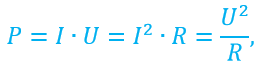
where P is the desired power, which is allocated to the R resistor;
I is the current in the circuit through the R resistor;
U - voltage on resistor R.
It's all great. But how to be in case alternating currentand in particular - sinusoidal? After all, there we have sausage sinus, the values \u200b\u200bof the current and voltage are changing all the time, now they are alone, after a moment - already others, i.e., expressing scientific language, they are time functions. Taking advantage of the knowledge obtained by us in previous introductory article , we can record this law of change of strength:
We will not repeat now that there is something that all this was thoroughly considered last time.
Absolutely similarly, you can write the dependence of tension from time for alternating sinusoidal current
So far we believe that we have in chains only resistors (Capacitors and inductances are absent), therefore, the voltage and current coincide in phase among themselves. Do not understand why so? Nothing, in the future we will analyze it in detail. In the meantime, this means that the phases both in the law of current change and the voltage change can be thrown out.
And now looking at these three lines with the formulas and comparing them between themselves, does any idea come to mind? For example, what could we substitute current or voltage in the power formula ... this idea came? It's just wonderful! Let's realize it now! Since we have a current, and voltages depend on time, all three received new formula for power Absolutely will depend on time.

Oh, straight in the eyes ripples from sinuses. But everything is quite simple and obvious from where what happened, isn't it? So this is the most formulas calculate instantaneous power at a certain point in time. The chip is that if an alternating current flows through a resistor, then in each moment of time it will be highlighted at all speaking different power: Otherwise, it cannot, since the amplitude of the current through the resistor is different all the time. Another thing is that visually, with a high frequency of current change, we will most likely not notice that: the temperature of the resistor will not have chaotically jump into the cycle of power changes, which stands out on it. This will be because the resistor itself due to its mass and heat capacity synthegrates these temperature differences.
So, with power more or less clear. And what about energy? Well, that is, with warmth, which stands out on the resistor? How to evaluate this very energy? To do this, we need to remember how the capacity and energy are connected. We have already affected this topic in the article about power in DC circuit . Then this question decided simply: with a constant current, it is enough to multiply the power (which does not depend on time and all the time is the same) at the time of observation and get the energy distinguished during this time. With alternating current, everything is more complicated, because the power it depends on time. And, alas, it's not necessary to do without integrals ... What is this in general this integral? How probably many of you know integral is just the area under the schedule. In this particular case, under the chart of power dependence on time P (T). Yes, so everything is simple.
So, energy (or work, which is essentially the same thing) in the AC circuit is considered as follows

In this formula Q. - This is the desired work (energy) of alternating current (everything is also measured in Joules), P (T) - the law of change of power from time, and T. - Actually, the segment of the time we consider, and during which the current works.
Generally speaking, this expression can be considered as a general case for direct current, and for variable (with an alternating current may be any form, not necessarily sinusoidal). In all EIH cases, it is possible to consider energy through this such integral. If we substitute here p (t) \u003d const (DC), then based on the feature of taking the integral from the constant, the result of the calculation will be absolutely the same as if we simply multiplied power for a while, so there is no point to bother and consider Integrals in the subject of direct current. But it is useful to know that there would be a certain single picture. Now, gentlemen, I ask you to remember the main conclusion from all this chatter - if we want to find the released energy during the timeT (no difference what current is a permanent or variable), then this can be done, finding the area under a graph of power dependence on time at the interval from 0 to T.
If you take the currents of sinusoidal and substitute specific expressions for the dependence of power from time, then the energy can be calculated according to one of the following formulas

Gentlemen, I will say right away, in my articles I will not tell how to take the integrals. I hope you know it. And if not - nothing terrible, do not hurry to close the article. I will try to build a presentation so that ignorance of integrals does not lead in your consciousness to Fatal Error. Very often they are not required at all to be considered with handles, but you can calculate in specialized programs or even online on numerous sites.
Let's now understand all of the above on a specific example. Gentlemen, especially for you, I prepared drawings 1. Take a look at it. An image is clipable.

Figure 1 - Power dependence on time for AC and DC
There are two graphics: the top shows the dependence of the power on time for the case of variable sinusoidal current, and on the lower - for the case of DC. How did I build them? Very simple. For the first schedule, I took this previously written formula.
We will assume that sinusoidal current amplitude equal I m \u003d 1 a, resistance of the resistor, on which the power dissipates, is equal R \u003d 5 ohms, and sinus frequency is equal f \u003d 1 Hzwhat corresponds to a circular frequency
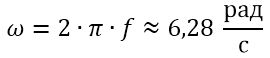
That is, the formula for which we build a graph of the power of alternating current has the form
It is for this formula that the top chart is built in Figure 1.
And what about the lower schedule? Gentlemen, well, everything is simple. I proceeded from the fact that through the same resistor R \u003d 5 ohms Permanent current I \u003d 1 a. Then how should be clear from law of Joule Lenza This resistor will disperse such a power.
![]()
Since the current is permanent, this power will be the same at any time. And for such wonderful cases of reference stability, the Great and mighty mathematics provides a schedule in the form of a straight line. What we see on the lower graph of Figure 1.
It is clear that once through our five-volume resistors flows the current, then some power is distinguished and some amount of energy is dissipated. In other words, the resistor is heated at the expense of energy released on it. We have already discussed that this energy is considered through the integral. But, as we said, there is also a graphical representation of this integral - it is equal to the area under the schedule. I shaved this area in Figure 1. That is, if we find what is equal to the area under the upper and lower charts, then we will define how much energy was released in the first and second case.
Well, with the lower chart, everything is simple. There is a rectangle with a height of 5 W and a width of 2 seconds. Therefore, the area (then you mean energy) is elementary
Note that this result exactly coincides with the formula obtained by us to calculate the DC energy in one of the past articles.
With the top chart, everything is not so simple. There we have an incorrect form and just so can not be said that this area is equal. Rather, you can say - it is equal to this is the integral
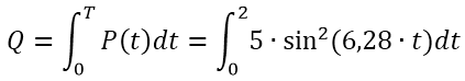
The result of the calculation of this integral is equal to a specific number and this number is just our desired energy that has been separated on the resistor. We will not paint taking this integral. Calculate such an integral with handles will not be difficult for a person, at least a superficial friend with mathematics. If it still causes difficulty, or just laziness to count himself - there is a huge amount of Capra, which will do it for you. Either it is possible to calculate this integral on any site: upon request in Google "Integrals online" is given a sufficient number of results. So, immediately go to the answer and it is equal

That's how. Energy that is released on a resistor in the flow of a sinusoidal current with an amplitude of 1 and almost two times less than the energy that will be distinguished in case of a permanent current of 1 A. It is clear - even visually in Figure 1 area under the top chart is noticeable below than under the bottom.
Somehow, the Lord. Now you know how to calculate power and energy in the variable circuit. However, today we looked at a rather complicated way. It turns out that there are methods simpler, using the so-called existing The values \u200b\u200bof current and voltage. But about this in the next article.
In the meantime - all of you great luck, thank you for reading, and for now!
Join our
As we have seen, in the sinusoidal alternating current circuit, generally speaking, the phase shift occurs between the applied voltage and the current:
Instant power. The phase shift depends on the relationship between the active and reactive resistances and thus from the frequency, since the voltage and current in the circuit varies with the frequency, then when the current operation count, it is necessary to consider such a small period of time so that the voltage and current values \u200b\u200bcan be considered permanent:
From here it turns out the following expression for instantaneous power:
Substituting the values \u200b\u200bfrom (1) here, we get
Taking advantage of trigonometric identity
refer (4) in the following form:
The expression for instantaneous power (5) consists of two terms: one of them does not depend on the time, and the second oscillates with a double frequency that means that the direction of the energy flow changes twice for each period of the application of the applied voltage: for some part of the energy period Enters the circuit from the source of alternating voltage, and within another part it is returned back. The average for the period of the flow of energy is positive, i.e. the energy enters the chain from the source.
Middle power. Existing values. If you are interested in the operation of alternating current over the time interval comparable to the period, then in the expression (15) for power, both terms should be taken into account. When calculating the work performed during the period of time, significantly exceeding the period, the contribution of the second term will be negligible. In this case, instead of (5), you can use the expression for the average power P:
![]()
Often this formula is written in the form
![]()
where I and is the so-called current values \u200b\u200bof current and voltage forces, many more appropriate amplitude values:
The use of existing values \u200b\u200binstead of amplitudes is convenient because in the load with a purely active resistance, where the expression (7) for power will be the same as for DC.
Losses in the transfer lines. The consumer is usually supplied with a voltage of a certain value therefore the same power P will be consumed when different values Current in the circuit I, depending on the phase shift between the current and voltage. For
small values \u200b\u200bof the current should be large, which leads to large thermal losses in the supply lines of the transmission line.
If - resistance of the transmission line, then the dissipated power of heat losses in the line is equal. Expressing current in the chain with (7), for getting
![]()
To reduce losses, it should be achieved as a smaller phase shift between the current and voltage in the load.
Most modern consumers electrical Energy The sinusoidal current is inductive loads, currents in which are lagging behind the phase from the power supply voltage. The equivalent scheme of such a consumer can be depicted in the form of sequentially connected active resistance and inductance (Fig. 143a). The corresponding vector diagram is shown in Fig. 144a. The current through the load is lagging behind the applied voltage to a certain angle power consumption. Power according to (7) is equal to
![]()
Fig. 143. Equivalent Consumer Diagram with Inductive Load (A) and the inclusion of auxiliary capacitor to increase

Fig. 144. Vector charts for chains depicted in Fig. 143.
From this formula, it can be seen that at a voltage, the same power could be obtained at any other current such that the vector representing its vector (shown by the stroke line in Fig. 144a) ends on the perpendicular by the end from the end to the direction as it is but if And at the same power, thermal losses in the supply wires will be less.
Reducing losses. How to ensure that the phase shift between voltage and current in the circuit decreased? It is easy to figure out that this can be connected parallel to the load auxiliary capacitor (Fig. 1436). The vector diagram in this case will be viewed in fig. 144b. Vectors depicting the applied voltage and current through the load will remain unchanged, and full current In an unbranched chain, equal to the amount of currents through the load and auxiliary capacitor, will be displayed by the vector by selecting the capacitor capacitor, it can be achieved that the phase shift to accept the specified value 9.
From fig. 1446 It can be seen that the length of the vector is equal
But with the help of (10) we find the amplitude value of the current in the capacitor associated with the amplitude value of the supply voltage of the formula substituting in (11), we find
![]()
Thus, there is quite simple and effective method Reducing losses in the transmission lines of the AC power lines associated with the reactive nature of the load resistance: the connection of the capacitor to the inductive load allows you to get equal to zero phase shift value 9.
High-voltage transmission lines. But even if the load resistance is purely active and the phase shift between the voltage and current is absent, i.e., thermal losses in the transmission line are still inevitable. Is it possible to reduce them in any way? The answer to this question gives Formula (9). It can be seen from it that at a given value of the power to the power consumer p, the thermal loss in the line can be reduced, or reducing the resistance of the transmission line wires, or increasing the AC voltage supplied to the consumer. The reduction in the resistance of the line is currently possible only to the known limits, therefore, before creating effective superconducting power lines with losses, it is necessary to deal with an increase in voltage.
Transformer. To convert voltage on power plants and consumers use transformers (Fig. 145). The transformer has a core of a closed form made of magnetic (easily magnetized) material that bears two windings: primary and secondary. The ends of the primary winding (transformer input) are connected to the network
aC, and the ends of the secondary winding (output) - to the consumer of electrical energy. EMF. electromagnetic inductionarising in the secondary winding is proportional to the number of turns in it.

Fig. 145. Transformer: general view, schematic device and conditional image in diagrams
Therefore, changing this number of turns, you can change the voltage at the output of the transformer widely.
Consider the principle of operation of the transformer. Suppose first the secondary winding of the transformer is open, and a variable sinusoidal voltage is fed to the primary. This is idling mode. Like any inductor inductor, the primary winding of the transformer can be considered as a successively connected inductance and the active resistance of the voltage on the inductive impact of the primary winding is ahead of the current phase and, therefore, the voltage on its active resistance to an angle, therefore, therefore, the amplitude values \u200b\u200bsubmitted to the primary voltage winding and voltages on and related by relation
![]()
Of course, it is impossible to directly measure and individually, since the primary winding, strictly speaking, do not have a successively connected inductance and active resistance each element of the winding has both inductance and resistance. This is the so-called chain with distributed parameters. But when calculating, it is possible to replace the real winding on the chain with concentrated parameters - the inductor inductor and the resistor, connected in series, because through each element of the source chain there is the same current.
Voltage on inductance at each moment of time compensates for self-induction EMF in the primary winding so
If the entire magnetic flux created by the current winding current is entirely, i.e. without scattering, penetrates secondary
the winding, the secondary winding induced in each turn of the secondary winding will be the same as in each turn of the primary winding. Therefore, the attitude electromotive power In the primary and secondary windings, equals the ratio of the numbers of turns:
![]()
At the outlet of the open secondary winding there is a voltage equal to the EDC induced in it:
Substituting here from (15) and considering (14), we get
![]()
Idling mode. Thus, the voltage value on an open secondary winding of the transformer is proportional to the voltage not fed to the primary winding, but only the voltage on the inductive impact of the primary winding from here immediately becomes clear the role of the transformer core. In fact, from formula (13) it follows that the inductance voltage will be the closer to the voltage supplied to the input of the transformer, the larger the inductive resistance of the primary winding compared to its active resistance the presence of a core from a material with high magnetic permeability leads to a multiple increase in inductance . At such a transformer at idle the sign minus means that these stresses are in antiphase. Due to the large inductive impact of the primary winding of the current in it, with the open secondary chain, small.
Transformer under load. When the secondary circuit of the transformer is closed to some load in the secondary winding, the current appears. The magnetic flux created by this current is directed so that, according to the law of the Lenz, it prevents the change in the magnetic flux being created in the primary winding. If the current in the primary winding remained unchanged, it would lead to a decrease in the magnetic flux. So, the inclusion of the load into the secondary circuit is equivalent to a decrease in the inductance of the primary chain.
But the decrease in inductive resistance immediately leads to an increase in current in the primary winding, to a decrease in phase shift between voltage and current and, therefore, to an increase in power consumed from the external circuit. Thus, if at idle the transformer is almost clean
inductive resistance, then as the transformer load increases, i.e. the current in the secondary chain, the nature of the resistance of the primary winding of the transformer becomes closer to the active one.
If the loss of energy in the transformer itself is small, then on the basis of the energy of energy conservation, the power consumed by the transformer is completely transmitted by the load. Then with the help of (6) you can write
where - the phase shifts between the current and voltage in the primary and secondary circuits.
The above consideration of the transformer's operation relates to an idealized case of a transformer without loss. In the real transformer, there are always losses associated with the release of joule heat in windings, with Foufo currents, with irreversible phenomena when moving the core and scattering the magnetic flux. But in modern transformers, total losses do not exceed a few percent of the transmitted power. The efficiency coefficient of transformers is very high and lies within 95-99.5%.
Straightening alternating current. For many practical applications, it is necessary to convert a variable sinusoidal current into a single direction. This goal is rectifiers, the action of which is based on one-sided conductivity of tube and semiconductor diodes.
It is possible to understand the effect of the rectifier, not intelligible into the physical nature of the mechanism of one-sided conductivity.
The simplest diagram of the rectifier is shown in Fig. 146a. This is a single-alpapid rectifier, in which the current through the load flows only for one half of each period of the applied sinusoidal voltage.

Fig. 146. Straightener schemes: single-alpapid (a), two-voltage (b) and voltage doubling (B)
In the bridge scheme of the rectifier shown in Fig. 1466, current through the load goes in the same direction during both half of each period. But in such a two-speech rectifier, the current is still pulsed. For smoothing these
pulsations use so-called electric filters if not only to get a current of one direction, but also a constant voltage.
In the figures shown in Fig. 146. a, b schemes The maximum voltage value (with perfect diodes) is equal to the amplitude value of the applied sinusoidal voltage. In shown in Fig. 146 In the rectifier diagram, the voltage on the load is almost twice as much as the amplitude value of the applied voltage, if the time of the discharge of capacitors through the load resistance significantly exceeds the period of sinusoidal voltage. This is the so-called voltage doubling scheme.
Tasks
1. The active resistance of the primary winding of the transformer makes it inductive resistance What voltage will be on an open secondary winding having twice as many turns if the primary winding is included in the 220 V voltage network?
Decision. The voltage on an open secondary winding is associated with a voltage at the inductive resistance of the primary winding by the relation (17). Therefore, in the case under consideration, for existing values, we have a choke if the boiler resistance (reactive load) and
In which cases, when calculating the AC operation, you can use the expression (6) for medium power, not an expression (5) for instantaneous power?
How can the heat losses in the power lines be reduced by changing the nature of the load resistance? Why in the AC networks, the energy consumer should have almost active as a whole resistance?
What is the advantage of using high voltage lines for electricity transmission?
What role does the core from the material with high magnetic permeability play in the transformer? Why is the iron core of the transformer collect from separate insulated plates?
From formula (17) it follows that the voltage transformation coefficient is determined by the ratio of the number of turns seemingly, with a loss of loss in the transformer, the less than the value as an active resistance increases with increasing number of turns. Why do the winding transformers usually contain a large number of turns?
Is it possible to include a transformer in a DC network?
Draw graphs of the flow rate of the current from time to the load of rectifiers, the diagrams of which are shown in Fig. 146 A, b.
Explain why in the rectifier scheme in Fig. 146 V voltage doubling occurs. Invite the straightening scheme in which voltage tripling happened on the load.


