We now consider the second case of the occurrence of induction current.
When driving the conductor, his free charges move with him. So on charges magnetic field There is a power of Lorentz. It causes the movement of charges inside the conductor. EMF induction, therefore, has magnetic origin.
On many power plants globe It is the power of Lorentz causes the movement of electrons in moving conductors.
Calculate EMF induction arising in the conductor moving in a homogeneous magnetic field (Fig. 2.10). Let the side of the contour Mn long I. Slips with a constant speed along the parties NC and MD, while remaining the parallel side of the CD. Vector magnetic induction uniform field Perpendicular to the conductor and is the angle α with the direction of its speed.
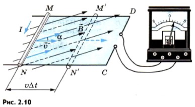
The force with which the magnetic field acts on the moving charged particle is equal to the module
F l \u003d | Q | υ b sin α. (2.5)
This force is directed along the MN conductor. Work of the power of Lorentz 1 On the way I is positive and amounts to:
A \u003d f l l \u003d | Q | υ BL SIN α.
1 This is an incomplete work of Lorentz's strength. In addition to the power of Lorentz (see formula (2.5)), there is a component of Lorentz forces directed against speed and conductor. This component inhibits the traffic of the conductor and makes negative work. As a result, the full work of Lorentz's strength turns out to be zero.
The electromotive force of induction in the conductor Mn is equal to the definition, the ratio of work on the movement of the charge Q to this charge:
This formula is valid for any conductor length L, moving at a speed in a uniform magnetic field.
In other conductors, the EMF contour is zero, since these conductors are fixed. Consequently, the EMF in the entire MNCD circuit is equal to and remains unchanged if the speed of movement is constant. The electric current will increase, since when the MN conductor is shifted to the right, the overall contour resistance is reduced.
EMF induction can also be calculated using the law electromagnetic induction (see formula (2.4)). Indeed, the magnetic flux through the MNCD circuit is:
F \u003d bs cos (90 ° - α) \u003d bs sin α,
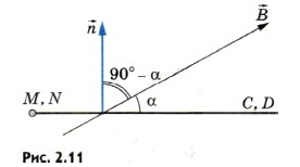
where the angle (90 ° - α) is the angle between the vector and the normal to the surface of the contour (Fig. 2.11, side view), A S is an area limited by the MNCD circuit. If we assume that at the initial moment of time (T \u003d 0), the MN conductor is located at a distance of NC from the CD conductor (see Fig. 2.10), then when the conductor is moved, the area S varies with time as follows:
S \u003d L (NC - υ T).
During the Δt, the contour area changes to ΔS \u003d -lυ ΔT. The sign "-" indicates that it decreases. Changing the magnetic flux during this time is:
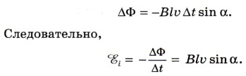
If the entire MNCD circuit moves in a homogeneous magnetic field, retaining its orientation in relation to the vector, then the induction of the induction in the circuit will be zero, since the flow F through the surface limited by the contour does not change. You can explain this. When the contour moves, forces arise in Mn and CD conductor (see formula (2.5)) acting on electrons in directions from N to M and from C to D. The total operation of these forces when around the contour clockwise or against it is zero.
EMF induction also occurs when the framework is rotated in the magnetic field, i.e., when the angle of OS (see § 31).
EMF induction in conductors moving in a constant magnetic field, arises due to the action on the charges of the conductor of the Lorentz power.
Questions to paragraph
1. What is the power of Lorentz and how is it directed?
2. What is the depends on the induction EMF, which occurs in the conductor, which moves in a variable in time magnetic field?
"" The phenomenon of electromagnetic induction "of physics" - the plate will almost stop. Flow. Magnetic field energy. The energy of a homogeneous magnetic field. The self-induction phenomenon plays an important role in electrical engineering. EMF of self-induction will maintain current in the chain. Expressions for circulation are always. Heating conductors. Racing due to the large amount of current change.
"Electromagnetic induction" - Michael Faraday. Material. Current value. Induction current. Evaluation. History. Electromagnetic induction and device. Generator alternating current. Sinwine. Historical reference. Level. Faraday experiences. Test list with tasks. Phenomenon. Unipolar induction. Top. Magnetic needle. Conductor. Video Fragment.
"Studying electromagnetic induction" - Portrait of Michael Faraday. Power of induction current. Questions. Questions and tasks. Statement. Electromagnetic induction. Emy's phenomenon. Electromagnetic field. Magnetic current energy. Direction of tension lines. Lenza rule. Magnetic stream. Magnetic flow through the surface. EMF induction in moving guides.
"Self-induction and inductance" - the phenomenon of the emergence of EMF. Self-induction. Manifestation of self-induction phenomenon. Conductor. Magnetic flow through the contour. Magnetic field energy. The inductance of the coil. Magnetic stream. Value. Units. Inductance. Magnetic current energy. EMF self-induction. Conclusion in electrical engineering.
"Field induction" - the flow of the induction vector. Magnetic induction stream. The contour is made of dielectric. EMF induction. The current is almost evenly distributed over the volume of wires. The dimension of the EDC induction. Fact. Circulation vector. High frequency currents. Toki Foucault. The conductor is fixed. The value of E.D. induction. Current density.
"Electromagnetic induction of Faraday" - Fizkultminutka. The principle of the generator operation. Magnet movement time. The appearance of the generator. Experience. Emy's phenomenon. Systematize knowledge. Opened Faraday. The phenomenon of electromagnetic induction. Solving the tasks of the linear structure. Induction current. Questions.
Total in the subject of 18 presentations
EMF induction in moving conductors
Using the determination of the magnetic field (5l16) and reducing the magnetic force acting on the conductor with a current, to the forces testing the charges moving in it, we received an expression for Lorentz (16l17). According to the determination given by us, this force is a third-party strength (for it is Noblonovskaya) and should not only occur when the charges are moved inside the conductor (i.e., if there is current), but also with any movement of the conductor itself in the magnetic field ( Since the charges in it are moving in it). Consequently, in various sections of such a conductor, generally speaking, third-party appear electrical powerConsidering electricity. These forces are called induction; To calculate them, consider the following simplest scheme.
Let a straight line of a cylindrical conductor l. moves in a homogeneous magnetic field B. And let his speed v. perpendicular B. and the axis of the conductor (Fig. 1). On the positive charges q. inside will, obviously, act the power of Lorentz, whose magnitude
| Fig. one. |
F L.= qVB., (1)
and the direction is shown in the figure. On the negative charges force F L. will act in the opposite direction. Arriving on the site l. EMF by definition
e 12 \u003d. A. 12 = F L L. = vBL (2)
and aimed for charges of both signs along the shown in Fig. one F. L..
If you imagine that the segment l. The conductor is part of a closed quasilinear chain, the circuit of which is depicted in Fig. 1 dotted line, the result obtained the result can be approved. Insofar as ,
vBL = = = = , (3)
where D. S. = l.D. x. - an increase in the area of \u200b\u200bthe contour, and DF \u003d D ( BS.) - vector flow B. through him during D t.. Since the rest of the plots are still, they do not appear third-party strength and, therefore, the complete EDC E acting along the entire contour is also determined by the expression (2). From fig. 1 shows that it is with the direction B. levovintovoy System. Thus, it can be written that
moreover, the minus sign corresponds to the rule established by us in the previous lecture, connecting the positive direction of circuit bypass and positive normal to it by means right Screw.
It can be shown that the ratio (4) is true in the most general case of arbitrary movement (including deformation) contour in stationary magnetic field. It expresses the so-called current of the induction of currents in moving conductors: the induction induction circuit is equal to the rate of change of magnetic flux through the outline and amounts to it (i.e. with change) not right- (this would mean a plus sign in (4)), and levovintovaya system.
 Fig. 2. Fig. 2. |
Note 1. In the Induction Law (4) it is about the flow of the vector B. Through a closed circuit r, although it is meant, of course, the flow of it through any surface based on this circuit (after all, it is through the surface and the stream of any vector) is determined. It is not difficult to see that the arbitrariness in the choice of this surface will not affect the value of F. Indeed, pulling two arbitrary surfaces on the outline S. 1 I. S. 2, we get a closed surface S. S, vector stream B. Through which according to equation (9l17) is zero. This means that streams through S. 1 I. S. 2 are equal and opposite, and in meaning (9l17) normal to S. 1 I. S. 2 It should be sent outward, that is, one of them is formed with the direction of bypassing the Governance, and the other is the left-hand system. Changing the direction of the latter to the opposite (and together with it and the sign of the corresponding f), we obtain the independence of the flow included in (4), from the selection of the surface S..
Note 2. Under the output of formula (2) it was assumed that the segment of the closed circuit in the magnetic field does not form, that is, the current does not flow in it, although the law (4) obtained as a result of its generalization relates to a closed conductive circuit. Let's see what effects will result in the appearance of the current in the conductor under consideration (Fig. 2). The emergence of speed u. Ordered movement of media directed along the axis of the conductor will cause a rotation to some angle A absolute speed v. abs charges regarding the direction of the conductory movement (i.e. v. ). At the same time the power of Lorentz F. L. Staying always perpendicular v. abs , It will also turn to the angle A relative to the axis of the conductor. However, the magnitude of its longitudinal component, creating EDC E 12,
F. || = F L. cos a \u003d. qV ABS B. cos a \u003d. qBV.
it will still be determined by formula (1), so that expressions (2) - (4) will remain fair. The transverse component equal to the largest
F. ^ = F L. sin a \u003d. qV ABS B. sin a \u003d. qBu.,
obviously, is a force directional towards Move the conductor. On overcoming this force (summing up for all moving charges within the volume of this conductor) and external work is spent necessary to move it in the magnetic field.
By turning the order of the arguments given in the previous lecture in the conclusion of the relation (15l17), we obtain for this total force F. ^ S known expression (5l16), where to develop it mechanical power
P ¢ fur = – F. ^ S. v. = – IBLV..
Power of the same third-party forces determined by the longitudinal component F. || , in a plot of 1-2 conductor in accordance with (2)
P p \u003d E 12. I. = vbli.
and turns out to be equal P ¢ fur . In this way,
P ¢ fur + P p = 0,
i.e. the full work of the magnetic field forces (as noted earlier) is zero. To maintain the traffic of the conductor, the external force, balancing F. ^ S should obviously develop power
P fur = – P ¢ fur = P p ,
which and "go" to work (per unit of time) existing third-party induction forces within it.
Similar phenomena occur and when moving in a magnetic field of the conductor, to the ends of which the potential difference is applied. If the conductor is not fixed, then the current on the section 1 - 2 (Fig. 3) flows only by electric forces. If I "release it", then the speed of magnetic force will appear v. and absolute speed of carriers v. abs will be devastated from the axis of the conductor. Immediately turn the strength F. L. Lorentz and its axial component will arise F. || aimed towards Toku. She will entail the appearance of a third-party EMC E 21 to compensate for the action of which (i.e. conservation of the continued current) source, it is necessary to develop an additional power E 21 I.. Repeating the above reasoning, it is not difficult to show that it is this power "stand out" in the form of a perfect conductor (per unit of time) mechanical work. Thus, in this case, the full work of Lorentz's strength, of course, turns out to be zero (for F. L. ^ v. abs). Negative part of it caused by F. || Compensated by the operation of the current source, the positive is the useful operation of the conductor.
 Fig. 3. Fig. 3. |


