Mooring tests.
Mooring tests are a technological stage of acceptance tests, the main purpose of which is to check the quality of ship construction, installation and adjustment of equipment; preliminary load testing of the main power plant and auxiliary mechanisms; checking the operation of systems and devices that ensure the survivability of the vessel; preparing the vessel for sea trials.
To carry out mooring tests, special places with sufficient depth are prepared, equipped with coastal mooring devices and having a quay of durable construction.
Mooring tests are carried out separately for mechanical, electrical and hull parts. The mechanical part is tested first, starting with emergency systems and mechanisms that ensure the safety of the vessel during testing (fire system, flooding and water pumping systems). After this, tests of auxiliary power equipment come: turbogenerators and diesel generators, auxiliary boilers, evaporators, desalination units, etc. Tests of the main power plant are carried out last. Ship systems, pipelines, electrical networks, power and survivability stations are tested simultaneously with the main mechanisms. Before testing the GTZA of a steam turbine installation, the operation of the shaft turning and shaft braking devices is checked, as well as the movement of the turbines into forward and reverse motion. During mooring tests of a steam turbine installation, hydraulic tests of pipelines of all systems are carried out, including fuel, fire, and steam; check the operation of auxiliary installations (start-up, feed, fuel pumps); carry out pumping of oil through the oil pipeline of the engine room; carry out hydraulic and steam tests of steam pipelines of the engine room; carry out tests of circulation and condensate pumps, as well as pipelines directly connected to turbines; carry out checking the power and lighting networks and starting the turbogenerator, as well as starting the GTZ for idling. Then the operation of the GTZ is checked at a rotation speed that is permissible according to the conditions of mooring reliability, the condition of coastal structures and the depth of the water area.
If the main installation on the ship is diesel, then at the beginning of its tests the serviceability of the shaft turning device, signaling of pressure drop and oil overheating, and turning off the fuel supply when the rotation speed increases above the permissible level are checked; engine starting qualities and starting air reserves. At the next stages, the operation of the main engines is tested at low and medium speeds. If there is an adjustable pitch screw or special unloading devices, the operation is also checked at full speed corresponding to the running mode.
On the hull part, during mooring tests, the displacement of the vessel is checked by measuring the draft according to the marks of the deepening, initial stability (by inclining method), as well as the operation of the anchor, steering, cargo, boat, mooring and towing, railing and awning devices, spars and rigging, outboard ladders, light and sound alarms, spotlights, running lights, bells.
When testing the steering device, the serviceability of the steering drive, the correct operation of the steering wheel position indicators and the operation of the limiters are checked. The anchor device is tested by etching and selecting one by one several links of the anchor chain on the brake band of the capstan or windlass, checking the passage of the anchor chain links through the fairleads, screw stoppers and along the sprocket of the anchor mechanism. In the cargo device, the reliability of the operation of the drums and brakes of the cargo winches, the reliability of fastening the cargo arms in a stowed manner, and the ease of opening and closing the cargo hatch covers are checked. For the lifeboat device, it is necessary to check the ease and correctness of the boats falling out, measuring the time of lowering and raising the boats, and checking the reliability of fastening the boats in a traveling manner.
Hull tests also include checking the operation of the galley, bakery, laundry and other living services on the ship. In addition, the reliability of the battening and tightness of doors, hatches, covers, portholes, etc. is tested. Household equipment is also checked: the reliability of its fastening, completeness.
http://www.transportway.ru/drives-990-1.html
ispitaniya-i-sdacha-sudov-v189543
http://baumanki.net/show-document/1-158055/9897f89c6ce4c9c56e05a83693c96550/2/
Sea trials
After mooring are carried out sea trials related to going to sea. Tests are carried out in a specially equipped water area called "measuring mile" ("measuring line"). This is a route of a certain length (for example, one mile), the beginning and end of which are marked by secant sections - a pair of coastal wooden shields with a vertical black stripe painted on them. When the lanes merge into one for an observer on the vessel, the vessel is on target. One alignment marks the beginning and the other the end of the measuring section. The direction of movement of the vessel is set either by guide lines or by the course indicated on the map.
To carry out the tests, a commission is formed, all the results of its work are documented in the form of protocols, where, in particular, the names and positions of the commission members, the time and conditions of the tests, information about the measuring instruments used, and measurement results are entered.
At the time of testing, the vessel itself, the measuring mile itself, the test conditions and measuring instruments are subject to certain requirements.
The vessel must be freshly painted (no more than 15 days, and in cold water - 30 days after leaving the dock), and must not have a list or trim. During sea trials, the displacement is usually less than when fully loaded, which is taken into account when processing the results. For this purpose, it is recommended to measure the drafts at the ends and on both sides amidships, which will make it possible to take into account the list and general bend of the vessel. During docking, the condition of the protruding parts is examined and, if necessary, their damage is repaired. Special requirements are imposed on the condition of ship propulsors. The geometric characteristics of the propellers are checked, and if there is damage to the blades, they are repaired.
Tests are carried out in calm weather: wind force is allowed up to approximately 3 points (for small ships - up to 1000 tons - up to 2 points, for large ships - over 20,000 tons - up to 4 points), and waves - up to 2 points (also for small ships - less, and for large ones - more), and the leading signs should be clearly visible. In the area of the measured mile there should not be a strong current, especially in the transverse direction, which distorts the speed measurement results. It is very important that the depth at the meter be deep enough to avoid the influence of shallow water on the resistance. Let us recall that a sharp increase in resistance begins at the Froude number in depth
where H is the depth of water at a measured mile. It is believed that the depth of water at a measured mile must exceed the greater of the two values calculated using the formulas

where B and T are the width and draft of the vessel, respectively; v is the highest speed of the vessel during testing. Thus, at normal speeds for transport ships of 15-16 knots, the required depth is approximately 25-30 m (if the vessel's draft is not very deep). As speed increases, the required depth increases rapidly.
Errors in speed measurements should not exceed 0.5%, time of passage of the measuring section - 0.2 s, number of propeller shaft revolutions per minute - 0.2%, torque on the propeller shaft - 3% of the torque at rated power, fuel consumption - 0.5%, wind speed - 2%, wind direction -5%, vessel draft - 2 cm, water and air temperature - 1 degree, start and end time of the run - 1 min.
The sea trials program provides for the vessel to move in several modes corresponding to the main engine speed from minimum to maximum, including nominal. For lead transport vessels with internal combustion engines, the following modes are mandatory: n = nom, n = 1.03nom, n = 0.91nom, n = 0.80nom, n = 0.63nom. In each mode, the ship makes three runs (the movement pattern is shown in Fig. 11.1; the curve that the ship describes when turning in the opposite direction is called the “coordinate”). To do this, it falls on a given course, which must be precisely maintained, the required rotation speed is set, and the established speed is picked up. There are observers on the ship with stopwatches, the number of which must be at least three. When passing the first target, the stopwatches start, the second – stop. The results are recorded in the protocol; if one of the three results is significantly different from the others, it is discarded. The speed of the vessel during the run is calculated as the quotient of the measured mile length divided by the average time. The average speed over three runs in one mode is calculated using the formula:


Rice. 11.1. Vessel traffic pattern on a measured mile
This takes into account the possible flow speed, which will be taken into account twice with a plus and twice with a minus. Moreover, if during the test the speed gradually changed approximately linearly, the formula allows you to eliminate the influence of the flow. This is faster and more accurate than determining the average speed over four runs.
Modern navigation systems make it possible to accurately determine the position of a vessel anywhere in the World Ocean and at any time, which makes it possible in principle to conduct high-speed tests in places not specially equipped for this purpose. However, the possible flow must be taken into account.
Another important measured characteristic is engine speed. On ships under operating conditions, it is measured by tachometers, but for test conditions their accuracy is insufficient. Here they use a tachoscope - a mechanical or electrical device that has a revolution counter and a stopwatch in one housing. The tachoscope roller rests against the engine shaft at the nose end; when pressed, both the stopwatch and the revolution counter start working, and when released they stop.
There are pulse tachoscopes operating on various physical principles. They are also used in cases where it is not possible to connect a tachoscope to the end of the shaft.
It is highly advisable to also measure engine power and propeller thrust or thrust. These measurements are technically more complex and less accurate. One way to measure the power of diesel plants is by fuel consumption. To do this, a measuring tank is included in the fuel pipeline, at the inlet and outlet of which there are transparent tubes with marks. At some point, the fuel pipeline is closed, and fuel from the tank begins to be consumed. At the moment when the fuel level is equal to the input mark on the tank, the stopwatch is started, and at the exit mark it is stopped. Knowing the specific fuel consumption in g/kWh and measuring the actual consumption in g/h, the power is calculated. But specific fuel consumption is not a completely stable characteristic and does not guarantee accuracy. The error of this method is approximately 4-5%.
Diesel power can also be measured using an indicator diagram - recording the pressure in the engine cylinder as a function of piston movement. There are special devices for this purpose. The sum of the powers of all cylinders gives the indicated power; the effective engine power is less due to losses in the engine (friction), which is taken into account by the mechanical efficiency, the value of which can be determined during bench tests of a diesel engine at the manufacturer, but is also not completely stable.
The power of steam and gas turbine plants is determined by other methods that we do not consider. On ships with electric propulsion, power can be determined from current parameters.
There are other, more complex ways. Since the power PD is uniquely related to the torque Q transmitted by the shafting (PD = 2пn * Q),
You can use torsiometers to measure the torque through the angle of rotation of the shaft f on a certain base 1. In this case

Here Ip is the polar moment of inertia of the shaft section; for solid round section with diameter D

Based on the operating principle, a distinction is made between electric and acoustic torsiometers. To convert the angle of twist into torque, knowledge of the shear modulus G is required, which is not a completely stable characteristic of the material. If you first calibrate the measuring section of the shaft to determine the shear modulus, the error in determining the torque is 2-3%.
Using strain gauges glued at an angle of 45 degrees to the shaft axis, it is possible to measure tangential stresses in the shaft (strictly speaking, shaft deformation from torsion), which can be easily converted into torque and power on the shaft. But here a serious problem arises in transmitting the signal from the rotating shaft to the stationary measuring equipment. Metal deformations are measured in hundredths of a percent, the same order of change in the electrical resistance of sensors that need to be measured with high accuracy. If readings are taken using slip rings and brushes, a resistance arises in the contact, the fluctuations of which can be of the same order of magnitude as the measured signal. To reduce this resistance, firstly, the pressing force of the brushes is selected, and secondly, attempts are made to use low-melting metals, for example gallium alloys (the melting point of pure gallium is 30 C). These errors can be avoided if a pre-amplifier and a radio transmitter are also placed on the rotating shaft, and a receiver and other measuring equipment nearby. Note that an additional error with this method arises due to inaccurate knowledge of the shear modulus of the shaft material.
Measuring the thrust or thrust of a screw is even more difficult to perform. For example, the thrust of a screw on moorings can be determined by the tension force of the cable connecting the ship to the shore, for which powerful dynamometers or metal plates with strain gauges glued to them are used.
The most accurate results can be obtained by replacing one of the intermediate shafts with a special insert equipped with instruments for measuring both thrust and torque. This insert is made specifically for a specific series of ships. A pressure meter (hydraulic or electric) can also be installed in a thrust bearing. The error in measuring the stop usually exceeds 5%.
Test results are processed and analyzed. To convert from displacement at the time of testing to full displacement, the Admiralty formula is usually used. It is desirable that the vessel reach its design speed at the nominal engine operating mode. Sometimes the test speed turns out to be less than the design speed. This may be due to insufficient depth at the measuring mile or due to the roughness of the skin - these cases should be excluded during preparation for testing. As we noted, errors may be due to the insufficient level of development of science and the characteristics of the constructed vessel. There are also cases when the test speed exceeds the design speed.
If during the tests the ship's speed, propeller shaft rotation frequency and power were measured (thrust often cannot be measured), then based on their results the coefficients of the associated flow and the influence of the unevenness of the velocity field on the torque, which were previously known from the data of model tests, can be corrected. Further, having calculated the resistance of the vessel, if there is a discrepancy with the results of model tests, it is possible to correct either the resistance or the suction coefficient.
Sometimes propeller elements are adjusted based on test results.
http://sudoremont.blogspot.ru/2014/08/hodovie-ispitaniya.html
Procedure for carrying out mooring and sea trials of electrical equipment.
Mooring tests
11.4.1 All consumers during mooring tests must be powered from standard ship generators.
In some cases, by special agreement with the expert, it may be possible to carry out mooring tests while powering ship consumers from shore-based power sources that have the appropriate parameters.
In the event that regular consumers of electrical energy do not provide the load of ship generators required during mooring tests, special load devices are used.
11.4.2 During mooring tests, the electric propulsion installation is checked:
.1 correct functioning of the installation in forward and reverse in all switching options provided for in the design documentation;
.2 serviceability of starting means for main diesel generators, backup exciters, fans, cooling and lubrication units;
.3 the ability to control the installation from backup positions;
.4 degree of sparking under the brushes at full load and reverse;
.5 serviceability of protection, alarm and blocking devices;
.6 insulation resistance of electrical machines, cable networks and auxiliary units of the electric propulsion system in cold and warm states;
.7 consistency of readings of propeller shaft speed indicators in the engine room and on the navigation bridge.
11.4.3 Ship power plant generators are tested in all modes together with the main switchboard.
When testing, check:
.1 performance of generators according to the test program;
.2 stability of parallel operation at different loads and load switching from one generator to another;
.3 serviceability of voltage regulators and devices for distributing active and reactive loads between generators;
.4 setting up automatic generator protection devices;
.5 degree of sparking under generator brushes;
.6 insulation resistance;
.7 serviceability of automatic synchronization and load distribution devices.
11.4.4 When testing batteries in operation, check:
.1 density and level of electrolyte in batteries;
.2 insulation resistance;
.3 operation of the charger and battery in discharge mode;
.4 activation of automatic protection devices (against reverse current, etc.);
.5 battery capacity for discharge for its intended purpose and voltage at its terminals;
.6 ventilation efficiency of a room or cabinet (on lead ships).
11.4.5 When testing switchgears, check:
.1 operability of devices under load in all modes in combinations and load variants provided for by the project;
.2 the possibility of transferring the control of installations from main posts (control panels) to local ones and their uninterrupted operation with such control;
.3 compliance of the specified positions of the controls with the actual operating modes of the controlled object;
.4 setting up automatic protection devices (by inspecting the operation settings and random testing of the machines, except for protection against short-circuit currents), interlocks and alarms;
.5 readings of measuring and recording instruments;
.6 insulation resistance.
11.4.6 When testing electric drives, the characteristics of each electric drive and its suitability for its intended purpose must be identified.
In addition to these tests, the following is checked:
.1 operability of the drive under load for the time specified in the test program (using measuring instruments, if necessary);
.2 the ability to control the drive from remote and local stations and turn it off using emergency switches;
.3 correct functioning of limit switches, brakes, interlocks, control devices, automatic protection and alarm devices;
.4 correspondence of the thermal protection settings to the currents of the protected electric motors;
.5 insulation resistance of electric motors and equipment in cold and heated states.
11.4.7 When testing control and signaling devices, check:
.1 consistency of operation of master and actuator devices (telegraphs, steering wheel position indicators, tachometers, etc.);
.2 serviceability of alarms, devices, apparatus;
.3 activation of emergency and fire alarms;
.4 insulation resistance.
11.4.8 During testing of the emergency electrical installation, the following is checked:
.1 reliability of automatic start-up of an emergency diesel generator;
.2 failure-free automatic connection of the emergency generator to the busbars of the emergency distribution board;
.3 uninterrupted connection of consumers to power from an emergency source of electrical energy (diesel generator or battery);
.4 uninterrupted connection of consumers to power from an emergency short-term source of electrical energy (if one is provided);
.5 values of emergency diesel generator parameters by measuring voltage, rotation speed and current during operation of all emergency consumers.
11.4.9 It is necessary to check the correct functioning of the blocking devices of the electric drive of the boat winch when turning on the manual drive and limit switches.
11.4.10 It is necessary to check the serviceability of main and emergency lighting fixtures, including at all critical objects of ship equipment, in the premises and spaces of the ship, at lifeboats, rafts, places for storing personal life-saving equipment, etc.
11.4.11 It is necessary to check the operation of the signal lights and the signaling of their malfunctions.
Sea trials
11.5.1 During sea trials, the operation of the ship's electrical installation is checked in all modes provided for by the program, under actual loads and conditions occurring while the ship is moving, as well as the correct functioning of electrical equipment that was not fully tested during mooring trials. The duration of tests and inspections of electrical equipment is determined taking into account the time specified in the relevant sections of these Rules when formulating the requirements for testing and inspection of ship technical equipment and devices driven by electrical energy.
11.5.2 When testing a ship power plant, the following is checked:
.1 sufficiency of generator power to power consumers in accordance with the load table for all modes of operation of the vessel, except for mooring;
.2 uninterrupted switching on of an emergency source of electrical energy in the event of a loss of voltage at the main switchboard and powering the necessary consumers from it;
.3 uninterrupted inclusion of a short-term emergency source of electrical energy (if one is provided) during the commissioning of the emergency diesel generator.
11.5.3 When testing an electric propulsion system, the following is carried out:
.1 checks specified in 11.4.2.1 , 11.4.2.3 And 11.4.2.4 ;
.2 measurement of reverse duration at different ship speeds.
11.5.4 Electric drives of pumps, compressors, separators, fans and other objects of marine equipment are checked when operating for their intended purpose in terms of reliability (uninterrupted) operation, switching on and off, switching to a backup set, if provided, the actions of remote controls for switching on and off the electrical drive, automatic activation of backup electric drives based on signals from adjustable parameters of the working environment in automated installations, etc.
Checks of operating electrical equipment for the absence of overloads, unacceptable temperature rises of housings, shells, panels, bearings, etc. are carried out using existing instruments or tactile methods. They also check the parameters of both their own vibration and vibration caused by the operation of the main engines and other objects of ship equipment or the ship’s propulsion system.
11.5.5 Electric drives of steering devices, their power systems (main and backup power lines), control systems, indication of the rudder position, signaling of the operation of the electric drive and its stop, etc. are checked when the steering device is operating in all intended modes.
11.5.6 The check is carried out both during the operation of two (if installed) electric steering drive units, and each power unit separately from all provided remote and local control posts when powering the electric drives of the power units and the control system from the main and backup power lines.
In this case, the cycle of shifting the rudder from side to side, provided for in Section. 9 , should be performed at least five times for each unit from each station and for each power line.
11.5.7 Electrical drives of anchor and mooring devices and boat winches are checked when testing the listed devices when the vessel is anchored and unanchored, leaving the berth, mooring and anchoring the vessel.
11.5.8 During sea trials, the insulation resistance of electrical equipment is measured both during its operation using panel board instruments for measuring insulation resistance, and with a portable megohmmeter immediately after decommissioning at the temperature of the equipment established during operation.
11.5.9 Electrical machines with commutators and slip rings are checked for the degree of sparking.
11.5.10 After sea trials, the scope of the inspection is established, during which it is necessary to open the bearings of electrical machines that heated up above normal during sea trials.
11.5.11 When opening an electric machine, check:
.1 technical condition of the supporting structures of the stator winding;
.2 location of winding slot wedges;
.3 technical condition and location of poles with their windings;
.4 reliability of fastening of rotating parts.
http://files.stroyinf.ru/data2/1/4293827/4293827304.htm#i1364208
Related information.
Each vessel must have a mooring device that ensures that the vessel is pulled to shore or floating mooring structures and that the vessel is securely fastened to them. The mooring device is used to secure the vessel to the pier, the side of another vessel, roadside barrels, palams, as well as constrictions along the berths. The mooring device includes:
mooring hawse and guide rollers;
bale strips (with and without rollers);
views and banquets;
mooring mechanisms (windlasses, capstan, winches); auxiliary devices (stoppers, fenders, brackets, throwing ends).
mooring ropes;
Mooring cables (ropes). Vegetable, steel and synthetic cables are used as mooring ends.
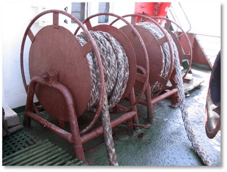
Steel cables are used less and less, as they do not take dynamic loads well and require great physical effort when transferred from the ship to the pier. The most common on sea vessels are steel mooring lines with a diameter of 19 to 28 mm. The steel mooring lines are stored on hand lines equipped with a brake pressed by a pedal to the cheek of the drum. On large-tonnage vessels, mooring eyes with a drive are installed.
Mooring lines made from synthetic cables are widely used. They are lighter than steel and vegetable moorings of equal strength, and have good flexibility, which is maintained at relatively low temperatures. It is not allowed to use synthetic cables that have not undergone antistatic treatment and do not have certificates.
To use the positive qualities of various types of synthetic cables, combined synthetic cables are produced. On mooring winches, where the mooring lines are steel, the part that goes to the shore is made of synthetic cable in the form of a so-called “spring”.
On ships transporting flammable liquids in bulk with a vapor flash point below 60 0 C, the use of steel cables is permitted only on decks of superstructures that are not the top of cargo bulk compartments, if cargo receiving and discharging pipelines do not pass through these decks. Cables made of artificial fiber may be used on tankers only with special permission from the Register (sparks may be generated when these cables break).
For timely detection of defects, mooring lines must neless often 1Raza at 6 monthsV be subject to thorough inspection. Inspection must also be carried out after mooring in extreme conditions.
Depending on the position relative to the vessel, mooring lines are called: longitudinal, clamping, springs (bow and stern, respectively).
The mooring lines at the outboard end have a loop - fire, which is thrown on the shore pal or secured with a bracket to the eye of the mooring barrel. The other end of the cable is secured to bollards installed on the deck of the vessel.
Bollards They are paired cast iron or steel cabinets located at some distance from each other, but having a common base. In addition to ordinary bollards, in some cases, especially on low-sided ships, cross bollards are used, which can be either double or single.
Mooring cables on bollards are secured by placing a number of hoses in the form of a figure eight so that the running end of the cable is on top. Usually two or three full eights are applied and only in exceptional cases the number of hoses is increased to 10. To prevent the cable from self-resetting, a grip is placed on it. To secure each mooring line brought ashore, there must be a separate bollard.
Cluses. To pass mooring lines from the ship to the shore, a mooring hawse is made in the bulwark - a round or oval hole bordered by a cast frame with smooth rounded edges. To pass mooring lines from automatic winches, they are usually installed UniverWithal rotary fairleads. Such fairleads protect the cable from chafing. On ships traveling through the Panama Canal, where the vessel is navigated through the locks using shore tractors, Panama hawsees must be installed, which have a larger radius of curvature of the working surface than that of the onboard canal, and are better suited for working with large-diameter moorings.
Bale strips. Bale strips are designed to change the direction of the mooring line. On most modern ships, bale strips are installed from separate two or three rollers. Bales without rollers are usually used only on small ships with a small diameter mooring cable.
Rolls reduce wear on cables and reduce the effort required to pull them out. Deflection (deck) rollers are installed near the mooring mechanism, which prevents the mooring line from skewing on the drum (turret).
Views and banquets. Banquets and views are used to store mooring ropes. The latter are a horizontal drum, the shaft of which is fixed in the bearings of the frame. The drum has discs on the sides that prevent the cable from coming off.
Mooring mechanisms. To select moorings, both mooring mechanisms specially installed for this purpose (for example, mooring capstans, winches, etc.) and other deck mechanisms (for example, windlasses, cargo winches, etc.) with mooring drums can be used .
To select mooring ropes on the forecastle, use tourAglasses windlass. Mooring capstans are installed to work with stern mooring lines. They take up little space on the deck; the capstan drive is located below the deck.
AutoOmaticesToIe shwarTovnye lebcaustic can be installed to work with stern and bow moorings (Fig. 6.50). The mooring line is constantly on the winch drum; no preliminary preparation is required before feeding or transfer to the bollards after tightening. Winches automatically pull up the vessel, taking up slack in the cable, or release a too-tight cable when the ship's position relative to the berth changes during cargo operations, or during high tide or low tide.
The mooring device must be kept in good condition, ensuring its constant readiness for action. Bollards, mooring fairleads, bale strips, and guide rollers must always be smooth enough to prevent premature wear of the cables. Rollers, rollers and other moving elements should rotate easily, be well spaced and lubricated. Chain and cable stoppers, verb-hooks must be in good working order.
If you have automatic mooring winches and mooring rotary fairleads, you should periodically rotate the fairlead rollers and regularly lubricate the rubbing parts.
All ends, cables, fenders, mats, throwing lines must be dried in a timely manner, metal parts must be cleaned and lubricated.
When mooring the vessel, the following must be done:
it is prohibited to leave steel mooring lines on the windlass drums even for a short time, since when the moorings are pulled or jerked, the shafts of the mechanisms may be bent;
in places with sharp fluctuations in water level, it is recommended to use vegetable cables or cables made of synthetic materials as mooring ends;
During loading and unloading, it is necessary to check that all mooring lines are equally covered and do not have excessive slack or are not too tight. Particular care must be taken to monitor moorings in ports where there are fluctuations in water levels;
During strong winds or currents, the mooring lines that experience the greatest stress should be evenly tensioned. In the presence of swell, the mooring lines should have some slack in order to reduce their tension when the vessel rocks;
during rain, mooring lines and painters made from plant ropes must be periodically etched, since when wet, they are shortened by 10 - 12% and can burst.
A steel mooring cable must be replaced if, anywhere along its length equal to eight diameters, the number of wire breaks is 10% or more of the total number of wires, as well as if the cable is excessively deformed.
The plant cable must be replaced if the heels are broken, damaged, significantly worn or deformed. Synthetic ropes must be replaced if the number of breaks and damage in the form of thread tears is 15% or more of the number of threads in the rope.
The mooring device is used to secure the vessel to the pier, the side of another vessel, roadside barrels, palams, as well as constrictions along the berths. The mooring device includes (Fig. 1):
- mooring ropes;
- bollards;
- mooring hawse and guide rollers;
- bale strips (with and without rollers);
- views and banquets;
- mooring mechanisms (windlasses, capstan, winches);
- auxiliary devices (stoppers, fenders, brackets, throwing ends).
Mooring ropes. Vegetable, steel and synthetic cables are used as mooring ends. The number and size of cables are determined according to the supply characteristics of a given vessel ().
 Location of mooring devices
 Plant ropes twisted from fibers of plant origin. Depending on the method of weaving and diameter, they are divided into ropes, lines, pearls, cords and cables. The material of manufacture is often reflected in the name of the cable. For example, a cable made from hemp bast fibers is called hemp. Competing with hemp cables are the so-called Manila cables (Fig. 2), which are twisted from the fiber of the leaves of the spinning banana - abaca. Such cables have the advantage of low weight, but are significantly inferior to hemp cables in flexibility. Sisal (Fig. 3), coconut, cotton, jute, linen (Fig. 4) cables are also used.
Advantages and disadvantages of plant cables:
- decrease when wet;
- susceptible to mold development;
- With use, the strength of plant cables quickly decreases.
 Rice. 2 Manila cable
  Rice. 3 Sisal cable
  Rice. 4 Lianoy cable
 Synthetic ropes have great advantages over plant-based ones. They are much stronger and lighter, more flexible and elastic, moisture-resistant, do not lose strength when wet and are not subject to rotting, and are resistant to solvents. Synthetic ropes are very elastic. At a load equal to half the breaking force, the relative elongation of braided eight-strand ropes reaches up to 35-40%, without losing strength.
Synthetic cables made from polymer materials. Depending on the brand of polymer, they are divided into polyamide, polyester and polypropylene.
Polyamide ropes(Fig. 5) are distinguished by their ability to absorb impact energy, they have excellent strength and very good wear resistance.
Polyester(polyester) cables (Fig. 6) are made from fibers of Lavsan, Lanon, Dacron, Dolen, Terylene, and other polymers. They are characterized by excellent resistance to climatic conditions, very good strength and wear resistance. Unlike polyamide ropes, they are flexible and soft even when wet. Polyester ropes are very suitable as mooring ropes and ropes for lifting heavy loads.
Polypropylene rope(Fig. 7) has average wear resistance and good strength. In the production of polypropylene ropes, film fibrillated thread or multifilament fiber is used, which themselves have excellent mechanical properties and high reliability. In the latter case, the rope turns out to be smoother and more pleasant to the touch. It has high resistance to bending, increased resistance to chemically active environments, high strength and at the same time is not hygroscopic, and therefore does not lose its properties when immersed in water. Such products are not susceptible to the destructive effects of fungi and bacteria, and therefore do not rot even after prolonged use in an environment with high humidity. Polypropylene ropes have high elasticity, which makes it possible to create various products with a fixed shape from them. Polypropylene mooring lines are especially convenient when sailing over long distances, as they float.
Synthetic fibers are easily distinguished by the following characteristics:
- if the sample does not sink in water, then it is made of polyethylene; if it sinks, then it is either polyamide or polyester;
- if during combustion there is dark smoke and the sample melts, then it is polyester; if it melts without changing color, then it is polyamide, polypropene or polyethylene;
- if the sample is moistened with 90% phenol or 85% formic acid (a few drops on a piece of glass) and the fiber dissolves, then it is polyamide; if the sample does not dissolve, it is polyester;
- if it does not dissolve and remains flexible - polypropene or polyethylene.
 Rice. 5 Polyamide rope
  Rice. 6 Polyester rope
  Rice. 7 Polypropylene rope
 Currently, composite and combined synthetic ropes using various types of fibers and threads are widespread.
It is not allowed to use synthetic cables that have not undergone antistatic treatment and do not have the appropriate certificates.
Steel cables They are used less and less often, since they do not withstand dynamic loads well and require great physical effort when transferred from the ship to the pier. The most common on sea vessels are steel mooring lines with a diameter of 19 to 28 mm. Cables are lubricated (tired) at least once every three months and each time after the cable is in water.
To ensure timely detection of defects, mooring lines must be thoroughly inspected once every six months. Inspection must also be carried out after anchoring on mooring lines in extreme conditions.
At one end of the mooring rope there is a loop - a light, which is put on the shore bollard or fastened with a bracket to the eye of the mooring barrel. The other end of the cable is secured to bollards installed on the deck of the ship.
They are paired cast iron or steel cabinets, located at some distance from each other, but having a common base (Fig. 8). In addition to ordinary bollards, in some cases, especially on low-sided ships, cross bollards are used, which can be either double or single.
 Rice. 8 Bollards: 1 - base; 2 - cabinet; 3 - cap; 4 - tide; 5 - stopper; 6 - butt
  Rice. 9 Fastening the mooring rope to the bollard
 Mooring cables on bollards are secured by placing a number of hoses in the form of a figure eight so that the running end of the cable is on top (Fig. 9). Usually two or three full eights are applied and only in exceptional cases the number of hoses is increased to 10. To prevent the cable from self-resetting, a grip is placed on it. To secure each mooring line brought ashore, there must be a separate bollard.
To pass mooring lines from the ship to the shore, a mooring hawse is made in the bulwark - a round or oval hole bordered by a cast frame with smooth rounded edges (Fig. 10). Currently, universal fairleads with a rotary cage and rollers are increasingly used (Fig. 11). Such fairleads protect the cable from chafing.
 Rice. 10 Mooring hawse
  Rice. 11 Universal fairlead
 In those places where there is no bulwark, instead of mooring fairleads, bale strips are installed to protect the cable from chafing and give it the necessary direction (Fig. 12). There are several types of bale strips. Bales without rollers are usually used only on small ships with a small diameter mooring cable. Rollers reduce wear on cables and reduce the effort required to pull them out. In addition to bale strips, guide rollers are also used to change the direction of the cable, which are located on the deck near the mooring mechanisms (Fig. 13).
 Rice. 12 Bale strips: a) - with three rollers; b) - with two rollers; c) - without rollers
  Rice. 13 Guide rollers
 Views and banquets. Views and banquets are used to store mooring ropes (Fig. 14, 15). The latter are a horizontal drum, the shaft of which is fixed in the bearings of the frame. The drum has discs on the sides that prevent the cable from coming off.
 Rice. 14 Storing the cable on the views
  Rice. 15 Cable storage on banquets
 Throwing ends (throwouts) and fenders. Parts of the mooring device also include throwing ends and fenders. The throwing end is made from a line about 25 m long. At one end there is a piebald - a canvas bag filled with sand (Fig. 16).
 Rice. 16 Workplace prepared for mooring: 1 - cable; 2 - ejection; 3 - portable chain stopper
 Fenders are used to protect the ship's hull from damage during mooring. Soft fenders are most often made from braided old plant rope. Cork fenders are also used, which are a small spherical bag filled with small cork. Recently, pneumatic fenders have been increasingly used.
Mooring mechanisms. Spikes, mooring simple and automatic winches, and windlasses (for working with bow mooring lines) are used as mooring mechanisms for selecting and tightening mooring lines. Mooring capstans are installed to work with stern mooring lines. They take up little space on the deck; the capstan drive is located below the deck (Fig. 17).
 Rice. 17 Mooring capstan
 On the forecastle, windlass mooring turrets are used to remove mooring ropes (Fig. 18). Automatic mooring winches can be installed to work with stern and bow moorings (Fig. 19). The mooring line is constantly on the winch drum; no preliminary preparation is required before feeding or transfer to the bollards after tightening. An automatic winch independently unwinds the moorings when it is over-tensioned or picks it up if the moorings have become slack.
 Rice. 18 Using the windlass head
  Rice. 19 Automatic winches
 The mooring cable selected using the mechanism is transferred to the bollards and secured. To prevent it from being etched when moving the cable, a stopper is first placed on it (Fig. 20).
 Rice. 20 Portable stoppers: a) - chain; b) - vegetable; c) - synthetic
 The stopper is attached to the eye at the base of the bollard or to the butt on the deck of the ship (Fig. 21). When working with steel mooring lines, you should use chain stoppers with a chain length of at least 2 m, a caliber of 10 mm and a plant cable at least 1.5 m long at the running end (Fig. 22). The use of chain stoppers for vegetable and synthetic cables is unacceptable.
 Rice. 21. Attaching the portable stopper to the bollard
  Rice. 22 Holding the mooring rope with a stopper
 The stopper is pulled along the mooring line in the direction of tension. When the mooring line is secured to the stopper, you should not abruptly release the cable from the capstan or capstan, so as not to jerk the stopper off. The mooring lines should first be carefully set by moving the capstan or windlass in reverse, without removing the hoses from the drum, and only after making sure that the stopper securely holds the mooring lines, quickly transfer the latter to the bollard.
On larger vessels, stationary stops can be used, which are installed on the deck between the hawse or bale strip and the bollard. Selecting and securing mooring ropes is greatly simplified when using bollards with rotating bollards. The mooring lines are placed in figure eights on the bollard bollard and fed to the windlass head. When the cable is pulled out, the bollard bollards rotate, allowing the cable to pass freely. After removing the cable from the windlass head, it will not be pulled out, since the bollards have a stopper that prevents them from turning in the opposite direction.
Suggested reading:
Content:
On the introduction of rules for spelling and pronunciation of certain words and expressions adopted in
naval language.
In the official correspondence and in various printed publications of the People's Commissariat of the Navy there is no unity in
designation of the same objects and concepts from the field of naval use.
To stop the inconsistency and maintain the purity of the naval language, it is proposed:
1. Adopt the rules for spelling and pronunciation of certain words and expressions adopted in the naval language.
2. All naval officers should study the rules and be guided by them both in literary work and in everyday official correspondence (reports, reports, orders).
3. Introduce the study of the Rules in naval educational institutions of all levels and ranks, where a course in Russian language and literature is taught.
Appendix: Rules for spelling and pronunciation of some words and expressions adopted in the naval language.
Chief of the Main Naval Staff of the Navy
Vice Admiral ALAFUZOV.
I APPROVED
First Sea Lord
Vice Admiral Alafuzov
September 16, 1944
Agreed with the Institute of Language and
writing system of the USSR Academy of Sciences.
Full member of the USSR Academy of Sciences
S. Obnorsky
Spelling and pronunciation rules
some words and expressions adopted
in naval language
1. Basic benefits
The main tools for resolving questionable spelling and pronunciation issues are:
a) Academician A. A. Shakhmatov, Essay on the modern Russian literary language. Approved by the People's Commissariat of Education of the RSFSR as a manual for higher pedagogical educational institutions, third edition. State Educational and Pedagogical Publishing House, Moscow - 1936
Theoretically based interpretation of general issues of Russian spelling and, partly, pronunciation;
b) Explanatory Dictionary of the Russian Language, edited by Professor D. N. Ushakov, ed. State Institute "Sov. Encyclopedia", OGIZ,
1935
Interpretation, pronunciation and correct spelling of words of Russian origin included in modern Russian
language (except proper names);
c) Great Soviet Encyclopedia
Spelling and pronunciation of most words, including many proper names, included in the modern Russian language;
d) Naval Dictionary, volume one, A-N, Naval Publishing House of the NKVMF USSR, Moscow 1939 Leningrad;
e) Naval Dictionary, volume two, O-Ya, State Naval Publishing House NKVMF, Moscow 1939 Leningrad
Spelling of naval terms that entered the language before the dictionary was compiled;
f) Manual on combat activities of the headquarters of the Navy units. State, naval publishing house NKVMF, Moscow 1940 Leningrad
Forms of combat documents, correct spelling of numbering of ships and units, links to maps, dates, orientation by cardinal directions, geographical names;
g) Rules for maintaining operational cards, State Publishing House of the NKVMF USSR, Moscow 1940 Leningrad
Correct spelling of abbreviations adopted in the Navy;
h) Manual on field service of the Red Army headquarters. Military publishing house of the People's Commissariat of Defense of the USSR,
Moscow-1942
Correct spelling of conventional abbreviations adopted in the Red Army;
i) Directory of ship personnel of the navies of foreign states 1943, Office of the Naval Publishing House of the NKVMF of the USSR, Moscow - 1943
Correct spelling of the names of modern foreign warships and auxiliary vessels in Russian and Latin transcriptions.
Everything that follows is based on the consensus guidelines of most of the benefits listed.
In the future, the upcoming publication of the Marine Atlas of the Hydrographic Directorate of the Navy will join the list of basic manuals.
d) documentary support for the correct spelling of geographical names.
2. About the spelling of some names
nouns
Nominative singular:
Prepositional singular case:
Nominative plural:
|
Write |
Don't write |
| agreements (pron. dogov ABOUT ry) | agreement |
| engineers | engineer |
| warships | military vessels |
| boats (pron. boatA ) | boats |
| conductors (pron. conductor ABOUT ry) | conductor |
| cruiser (pron. cruiser A ) | cruisers |
| pilot (pron. pilot A ) | pilots |
| midshipman (pron. midshipman A ) | midshipmen |
| officers | officer |
| ports | port |
| seiners | seiner |
| ships | vessel |
| merchant ships | merchant ships |
| transports | transport |
| mooring lines | mooring lines |
| navigator (pron. navigator A ) | navigators |
| anchors | anchors |
Genitive, accusative and prepositional plural cases:
3. About the spelling of some adjectives
|
Write |
Don't write |
| two-kilometer | two-kilometer, 2-kilometer |
| Odessa direction | Odessa direction |
| Odessa naval base | Odessa naval base |
| operational direction | operational direction |
| operational thinking | operational thinking |
| identification signal | identification signal |
| experimental pool | experimental pool |
| pilot test | pilot test |
| experimental kit | experimental kit |
| prototype | prototype |
| experimental training | experimental training |
| experienced sailor | - |
| experienced officer | - |
| smooth networks | smooth networks |
| Romanian coast | Romanian coast |
| three-gun salvo | 3-gun salvo |
| typical operation | - |
| typical situation for the operation in the Gulf of Finland | - |
| The Gulf of Finland | - |
| Finnish coast | - |
| Finnish skerries | - |
| mooring testing of mechanisms | mooring testing of mechanisms |
4. About the spelling of numerals
Numbers up to nine inclusive to indicate the number of objects should be written in words: eight boats. The number of objects over nine can be shown in words and numbers: ten boats (10 boats). When showing the number of items in numbers, write the items themselves in words: 10 minesweeper divisions, not 10 DTSH (the latter abbreviation means the tenth minesweeper division).
5. About the use of some verbs
6. About the correct spelling of geographical names
The correct spelling of the geographical name is selected from the Index of the Maritime Atlas published by the Hydrographic Directorate of the Navy or from the latest edition of the corresponding navigation guide of the State Administration of the Navy of the USSR (using an alphabetical index). If there is no navigation route covering the required area, then you should be guided by the spelling adopted in the Great Soviet Encyclopedia or in the Index of the Great Soviet Atlas of the World.
If it is necessary to mention in an official document a foreign geographical name that is not in the Maritime Atlas and in the directions of the Main Directorate of the Navy of the USSR, write it in the Latin alphabet, using the transcription of the directions of the British Admiralty.
If a private geographical name consists of two words, both words are written with a capital letter: Western Gogland Reach, Eastern Bosphorus.
7. About orientation in space
All directions should be given in degrees or in bearings, adhering to the following provisions:
a) give in degrees courses, bearings, light sectors of beacons, alignment directions, directions from noticeable points to find the location of danger, signs of a floating fence, etc.;
b) the directions of winds, currents and shores should always be given in rumbas, and the construction of the phrase in this case should exclude the use of the name rumba in the form of an adjective. For example, you should write the wind S, the current goes to NW, the coast changes direction to SO, the coast has the direction NO - SW or the wind is north, the current goes to the north-east, but not “south wind”, “north-west current”, “ south-west direction”, etc.;
c) directions characterizing the orientation of an object (shore, cape, tip, etc.) relative to the cardinal points, always be given in Russian words, for example, northern shore, southwestern tip, east of the alignment, etc.;
d) directions that give orientation to coastal objects from the sea can be given in bearings and degrees, for example, Cape Krugly on ONO at 3 miles, Mount Vysokaya at 136° at 2.5 miles.
8. About the spelling of surnames
Surnames coming from Slavic roots ending in in, n, h, skiy, tskiy, y, y, a(like Danilin, Ivanov, Matveev, Ivanovsky, Ivanovich, Bely, Ivanetsky, Lebeda), as well as Soviet surnames that came from non-Slavic roots, and, finally, foreign surnames - Russified or firmly established in Russian writing and, moreover, consonant with Russian words ( Altvater, Amundsen), are declined in full accordance with the rules of nouns or adjectives.
Surnames of Slavic origin O and all surnames of non-Slavic origin, discordant with Russian words, are not declined (Konyushenko, Traverse. Georgadze, Georgishvili, Yusuf-Zade).
9. About the spelling of ship names
The gender of the name of a ship (as a part of speech - a noun or adjective), given together with the designation of its class or type, is subject to the gender of the designation of the class or type of ship.
Examples: the cruiser "Aurora" was taken out of the harbor; the submarine "Walrus" left the harbor; The schooner "Sailor" entered the harbor.
In official documents, the names of ships must be preceded by class or type designations: destroyer "Proud". In this case, only the designation of the class or type is declined, and the name of the ship remains unchanged.
Example: It is not advisable to go out without the destroyer Gordy.
10. About abbreviations
The overuse of abbreviations makes reading difficult, obscures the meaning and sometimes leads to erroneous interpretation of the text.
The use of abbreviations is permitted only there. where this is inevitable: in operational documents, in logs - watch, combat, historical, in official manuals and in tables, where this is caused by lack of space or the desire to avoid repetition of cumbersome designations.
Moreover, in publications intended for a wide range of readers. Only those abbreviations that are given in Rules for maintaining operational cards and in Manual on field service of the headquarters of the Red Army . Only in publications intended for a narrow circle of readers belonging to one special service, conventional abbreviations adopted within this service are allowed.
When using the legal abbreviation BTSH, remember that this means a basic minesweeper, and not a “high-speed minesweeper”; KATSCH is a minesweeper-boat, and not a “boat minesweeper”.
Abbreviated designations of ship classes given in operational documents are doubled only in cases where we are talking about a plurality of ships without indicating their number.
Example:
CL CL line up in a wake column, but: three CL line up in a wake column.
The number of ships, the class of which is given by an abbreviated designation, is written in words.
Example: three SKR (three patrol ships).
The number preceding the abbreviated designation of the ship's class indicates the serial number of the ship.
Example: 3 SKR = third patrol ship.
An abbreviated designation of a ship class or aircraft type, given without indicating a number, is written without quotation marks.
Example: two MO boats, a U-2 plane, one La-5.
However, the aircraft type, designated by the full name of the designer or the full conventional name, is written in quotation marks.
Example: two Douglass, three Flying Fortress aircraft.
The abbreviated designation of the class or type of ship in combination with a number, thus depicting the name (proper name) of the ship, is written in quotation marks (until the second half of the 19th century, the names of ships were written without quotation marks, but were highlighted in italics in print), For example: "MO-114", "M-172", "Shch-21".
Ultrasonic underwater surveillance device of the type developed by the Anglo-American organization Anti Submarine Defense
International Commitee, call Asdik, not Azdik.
Abbreviated designations for metric measures and various physical quantities adopted in the USSR are depicted in strict accordance with existing all-Union standards (OST).
For example: m (meter), km (kilometer), kg / (kilogram), t (ton) without dots (particularly because m serves as an abbreviation for minute, and t can be taken as an abbreviation for the word thousand). The word mile has no abbreviation and is always written in full (m means meter, and m means minute). The word cabletov is abbreviated as cab.
General names of geographical locations (island, cape, mountain, city) in all cases except for sailing directions should be written in full.
For example , Gogland Island. In driving directions, the following abbreviated designations of geographical points are allowed, with proper names following them:
Island - o.
River - r.
Village - village
City - city
Cape - m.
Lake - lake
In other cases (besides driving directions) abbreviation of common names of geographical objects can lead to confusion (b. can be understood as a bay, bank, base and tower, g. can be understood as a city and as a mountain, o. as an island and as a lake, etc.).
In operational documents, charters and in popular literature, the abbreviated designation of geographical coordinates should be depicted as follows: lat. 00°00" N, long 00° 00" 0 or
lat. 00 ° 00" north., long. 00 ° 00" rest.
In the combat log, in accordance with the Rules for Maintaining Operational Maps (p. 28), with abbreviated coordinates, the latitude is given without indicating north or south; longitude - without specifying eastern or western: w = 59°17",0, d = 27°18",5.
In scientific works (according to OST 6345), geographic latitude and longitude are designated fi φ And lambda λ .
Avoid in written documents naming classes of ships with abbreviated designations allowed (according to the Rules for Maintaining Operational Charts) for transmission by telephone and semaphore: battleship, destroyer, gunboat, submarine.
In operational documents drawn up in a hurry, it is allowed to use the abbreviations LC, EM, CL, PL, and in all other cases write in full: battleship, destroyer, gunboat, submarine.
11. About the use of Russian and Latin alphabets
Names of foreign ships in newspapers, magazines (except magazine "Sea Collection"
) and in popular literature write in Russian letters, using the Russian transcription of the alphabetical index "Directory of ship personnel of foreign navies."
If at the same time it is necessary to cite the original foreign language name, then write it in Latin alphabet in brackets after the Russian name. In the magazine "Sea Collection"
and in printed publications of a scientific research nature, the names of foreign ships of modern times should be written in Latin alphabet in the transcription of the publication corresponding to the time "Directory of naval personnel
foreign fleets"
or Jane's Fighting Ships. When describing the past names of ships of eastern states that did not use the Latin alphabet at one time (Greece, Egypt, Iran, Turkey, Siam, China, Japan), write in Russian.
Head of the Department of the State Medical School for the study and generalization of war experience
Captain 1st Rank N. OZAROVSKY.
Notes in the order:
The Russian language allows equally both forms: boats - boats. cruisers - cruisers, however, in the everyday life of the fleet and in naval literature to the second
half of the 19th century, the shape of the boat and cruiser was firmly established: "The first mine boats had such little speed that they could not overtake
no warship. . . "
(S. O. Makarov. Discussions on issues of naval tactics, p. 321. Voenmorizdat. 1943).
So: boats. cruisers, pilots, midshipmen, navigators, anchors - represent a common literary form.
Uniform: boat, cruiser, pilot, midshipman, navigator, used in naval language as a professional uniform.
Relating to experiments (experimental).
Experienced.
About the movement of the boat.
* Geographical private name - proper name - is written with a capital letter.
Finnish, Romanian and all other coasts - common nouns, may be different - are written with a lowercase letter.
Let it sink.
The mooring device is intended for attaching a vessel to a pier, mooring barrels and beams, or to the side of another vessel.
The device includes:
Mooring ropes;
Bale strips;
Guide rollers;
Mooring mechanisms.
Accessories:
Stoppers;
Throwing ends;
Mooring ropes (mooring lines, mooring lines) There are steel, vegetable and synthetic.
Mooring ropes (ropes ). They are used as mooring lines vegetable, steel and synthetic cables . Steel cables are used less and less, as they do not take dynamic loads well and require great physical effort when transferred from the ship to the pier. The most common on sea vessels are steel mooring lines with a diameter of 19 to 28 mm.
Service life of ship cables:
Steel cables – running rigging from 2 to 4 years ;
Vegetable and synthetic ropes - cable work - 3 years , Perline – 2 years ;
- other cables – 1 year.
The ends of the mooring ropes end in a loop called - fire.
Number mooring ropes on the ship, their length and thickness determined by the Register Rules .
The layout of the mooring lines is shown in rice.

Main mooring lines served from the bow and stern ends of the vessel in directions excluding the movement of the vessel along the berth and departure from it . IN depending on the direction mooring lines got their names . Moorings wound up from the bow and stern ends of the vessel , holding vessel from movement along the pier are called bow (1) and stern (2) longitudinal. Mooring line, whose direction opposite to longitudinal called spring. Nasal (3) and stern (4)springs are used for the same purposes as longitudinal ends. Moorings, wound up perpendicular to the pier , are called nasal (5) And stern (6) clamping. The clamping ends prevent the vessel from moving away from the berth in a strong wind.
Bollards – cast or welded bollards (steel and cast iron) for fastening mooring cables. On transport vessels, paired bollards with two pedestals are usually installed on a common base, having hot flashes to hold the lower cable hoses, and hats does not allow the upper ropes of the mooring line to jump off the bollards.

Bollards are also installed with cabinets without tides,
and bollards with cross .
Bollards with cross convenient for mounting mooring lines , aimed from above at an angle to the deck . Similar bollards install in the bow and stern parts of the vessel both sides symmetrically .
Sometimes on ships they install one pedestal bollards – bitengi , which are used for towing .
Bitengi- represent massive cabinets , the bases of which are attached to upper deck or passed through it and attached to one of the lower decks . To hold the cable on the bits there are spreaders .
Convenient when performing mooring operations – bollards with rotating pedestals, equipped with a locking device.
Pinned to berth moorings put "eight" two or three hoses on the bollard bollards, and then on Turkish girl windlass. When cable is chosen , cabinets rotate and pass the cable freely . When the cable is selected, the bollards rotate and pass the cable freely. At the right moment, remove the cable from little Turks and apply and apply additional hoses to the bollard bollards. At the same time, the stopper keeps the cabinets from rotating.
Cluses – devices through which mooring lines are passed from a vessel. Cluses are steel (cast iron) with holes round shape ,

or oval shape , bordering the holes in ship's bulwark .
Working surface hawse has smooth curves , excluding sharp bends of mooring lines .
For mooring to on board small-size floating craft, use fairleads with tides - horns.
In places where instead bulwark made railing , special fairleads are fixed on the deck at the edge of the side.
Strong mooring line friction about the working surfaces of the fairleads of these structures leads to rapid wear of cables , especially synthetic ones, so they are widely used on ships universal fairleads ,
And rotary universal fairleads.

A universal hawse has vertical and horizontal rollers freely rotating in bearings, forming a gap into which the cable fed to the shore is passed. Rotating one of the rollers when pulling the cable from any direction significantly reduces friction. The rotary universal hawse has a rotating ball-bearing cage in the body.
Bale strips have the same purpose as mooring hawse .
By design, bale strips are simple ,

with biting ,

with one roller ,

with two rollers ,

with three – Rolls.

For guiding mooring lines supplied to high berths and ships with high sides, use closed bale strips.
The most widespread bales with rollers , the use of which is significant reduces the effort required to overcome the frictional forces that arise when pulling out the cable .
To route mooring cables from the hawse to the mooring mechanism drums, metal bollards with guide rollers.

Views – designed for storing mooring ropes. They have locking devices . Install them in bow and stern parts of the ship not too much far from the bollards .

Mooring mechanisms– are used to pull a vessel with mooring lines in place to the pier, the side of another vessel, a barrel, to pull the vessel along the pier, as well as automatically adjust the tension of the mooring lines when the water level fluctuates, tidal water currents, or changes in draft during loading or unloading of the vessel.
Mooring mechanisms include:
- windlass;
- mooring spiers;
- anchor mooring winches;
- simple and automatic winches.
Windlasses and mooring capstans, have drums (turrets) that are used to pull out mooring ropes .

On ships that do not have stern anchor device , installed at the stern of the vessel mooring capstans that do not have a chain drum.

Vertical location of the axis of rotation of the capstan mooring drum allows select moorings from any direction . Concave external the surface of the capstan drum and windlass can be smooth or have vertical welps - rounded ribs .
Welps– prevent the cable from sliding on the drum. However, due to kinks on them cause mooring ropes to be damaged more quickly . Therefore, with widespread use on ships synthetic ropes subject to greater friction when working on a capstan, capstan drums make smooth .
Anchor mooring winches, installed on some ships instead windlasses , and are used during mooring operations in the same way as windlasses.

Simple mooring winch It has electric motor with built-in disc brake . The rotation of the winch engine is transmitted through mechanisms inside to the shaft with the mooring drum. Through work disc brake, you can adjust the speed of rotation of the mooring drum.

Automatic mooring winch differs favorably from a simple winch in that it can work in manual and automatic mode . IN manual mode the winch is used for pulling the ship to the pier and for selecting the given cables. After the cable is pulled tight, it remains on the winch drum . winch switch to automatic mode , setting required cable tension force . At change, for any reason, in the tension force of the cable, the winch automatically picks up or releases the mooring cable, ensuring constant tension of the mooring cable .

Automatic winches are manufactured in two versions:
- with mooring turret , connected to the mooring drum by a release coupling;
- without the turret , which are installed near the windlass and capstan.
Stoppers serve to hold mooring ropes in in a tense state when transferring them from the mooring mechanism drum to the bollards.
There are stoppers: chain (Fig. a), vegetable or synthetic (Fig. b).

Chain stopper represents rigging chain with a diameter of 10 mm , And length 2 – 4 m , with a long link for fastening with a bracket to the deck butt, at the other end of the stopper there is a vegetable or synthetic cable at least 1.5 m long . And thick V twice as thin than the mooring end.
Stopper from vegetable or synthetic rope made from the same material as mooring ropes only twice as thin.
Throwing end necessary for supplying the mooring cable to the shore when the vessel approaches the pier.

Throwing end- This vegetable or synthetic tench thick 25 mm , length – 30 – 40 m , on one side of which is tied lightness (a weight braided with a thin plant torso) for increasing throwing distance , the other end is tied to the mooring line light .
Fenders.
Fenders – intended for protection of the ship's hull from impacts on the quay wall , or about on board another ship during mooring operations and vessel anchorage.

Fenders there are soft And hard
Soft fenders- This bags filled tightly with elastic material And braided with strands of plant rope or packed in special cases . Soft fenders have a fender with a thimble for attaching a vegetable or synthetic cable to it, the length of which should be sufficient overboard at low berths and the smallest draft.
Hard fenders- wooden blocks suspended on cables from the side of the ship. To give such a fender elasticity, it is braided along its entire length with vegetable or synthetic cable.
Steering device of the ship.
Steering gear- serves for ship control . With steering device you can change the direction of the ship's movement or keep it on a given course . During To keep the ship on a given course, the task of the steering device is to counteract external forces:
Currents that can cause the ship to deviate from its intended course .
Steering devices have been known since the appearance of the first floating craft. In ancient times, steering devices were large swinging oars mounted at the stern, on one or both sides of the ship. During the Middle Ages, they began to be replaced with an articulated rudder, which was placed on the sternpost in the center plane of the ship. It has been preserved in this form to this day.
The steering device consists of the following parts:
- Steering wheel allows you to keep the ship on a given course and change the direction of its movement. It consists of a steel flat or streamlined hollow structure - rudder , and the vertical rotary shaft – ballera , rigidly connected to the rudder blade. To the top end ballera brought out onto one of the decks sector planted or lever - tiller, to which an external force is applied to turn baller .
- Steering motor the stock rotates through the drive, which ensures rudder shifting. Engines are steam, electric and electro-hydraulic. The engine is installed in the tiller compartment of the vessel.
- Control station serves for remote control of the steering motor. It is installed in the wheelhouse. The controls are usually mounted on the same column as the autopilot. To control the position of the rudder blade relative to the center plane of the vessel, indicators are used - axiometers.

Depending on the principle of operation, they are distinguished:
Passive steering wheels;
Active steering wheels.
Passive They are called steering devices that allow the vessel to turn only while underway, while the water is moving relative to the hull of the vessel.
Unlike him active The rudder allows you to turn the vessel regardless of whether it is moving or stationary.
Based on the position of the rudder blade relative to the axis of rotation of the stock, the following are distinguished:
- simple steering wheel – the plane of the rudder blade is located behind the axis of rotation of the propeller ;

- semi-balanced steering wheel– only a large part of the rudder blade is located behind the axis of rotation of the propeller, due to which a reduced torque occurs when the rudder is shifted;
- balance steering wheel– the rudder blade is located on both sides of the rotation axis so that no moments arise when shifting the rudder.
Active steering device– an electric motor is built into the rudder blade, driving the propeller into rotation. The electric motor is placed in the nozzle to protect it from damage. By turning the rudder blade together with the propeller at a certain angle, a transverse stop is created, which makes it easier to turn the vessel. The active rudder also performs its functions while the vessel is at anchor. Active rudders are usually installed on special vessels where high maneuverability is required.

To facilitate the maneuverability of the vessel during mooring operations, bow and stern thrusters are used. Thrusters are distinguished:
- thrusters With counter-rotating screws.

- thruster with reverse rotation of the propeller.
In order for the active steering device to operate, the passive rudder blade must be at a certain angle. The rudder stock is driven into rotation by a steering gear installed below the deck at the stern of the vessel..
Operating principle electric steering device.

1 manual steering wheel drive (emergency drive);
2 tiller;
3 gearbox;
4 steering sector;
5 electric motor;
6 spring;
7 rudder stock;
8 rudder feather;
9 segment worm wheel and brake;
10 worm.
If it is needed turn the rudder , need to run, electric motor with a certain rotation speed which is associated with steering column on the navigation bridge . Through electrical devices (selsyns, rotating transformers ) torque from the helm steering column on the navigation bridge transmitted to electric motor of the steering device and from it to the rudder blade.
At Electric steering malfunction the steering wheel is driven to movement using a manually controlled mechanism consisting of a manual steering wheel . By turning helm through worm gear rotation is transmitted to tiller and from him to rudder stock .
On modern ships use a steering device with an electro-hydraulic motor .

1 connector for connecting to the ship's electrical network;
2 ship cable connections;
3 spare canister with hydraulic fluid;
4 steering pump;
5 steering column with telemotor sensor;
6 indicator device;
7 telemotor receiver;
8 engine;
9 hydraulic steering machine;
10 rudder stock;
11 steering indicator sensor.
When the steering wheel on the steering column in the wheelhouse rotates, the transmitting and receiving telemotor sensor on the steering column and steering gear is triggered. Flowing under pressure into in the pipeline, the liquid moves the rod in the telemotor receiver, which transmits movement to the steering pump in the appropriate direction . From the steering pump, the movement is transmitted to the steering stock.


