Instant power p.arbitrary plot of chain, voltage and current of which vary by law u.=U. M sin ( t.), i \u003d i M sin ( t-), has appearance
p \u003d ui \u003d u M sin ( t.)I. M sin ( t- ) \u003d U. M. I. M / 2. =
\u003d U.i.cos. - UIcOS (2. t -) = (UIcOS - UIcOS COS2. t.) - UI.sin sin2. t.. (1)
ACTIVE POWER OF AC Chain P.determined as the average value of instantaneous power p.(t.) over a period:
since the average for the period of the harmonic function is 0.
From this it follows that the average power over the period depends on the phase shift angle between the voltage and the current and is not zero if the circuit section has active resistance. The latter explains its name active power. We emphasize once again that in active resistance there is an irreversible transformation of electrical energy into other types of energy, for example, to thermal. The active power can be defined as the average for the period of energy flow rate into the circuit section. Active power is measured in watts (W).
Reactive power
When calculating electrical circuits, the so-called reactivepower. It characterizes the processes of energy exchange between the reactive elements of the chain and the sources of energy and is numerically equal to the amplitude of the variable component of the instantaneous power of the chain. In accordance with this, the reactive power can be determined from (1) as
Q. = UIsin
Depending on the sign of the angle, the reactive power can be positive or negative. The unit of reactive power to distinguish it from the unit active, is not called watts, but a volt-amper reactor. The reactive capacities of inductive and capacitive elements are equal to amplitudes of their instantaneous capacities. p. L I. p. C. Taking into account the resistance of the elements, the reactive power of the inductor and capacitor coil is equal Q. L \u003d. UI=x. L. I. 2 I. Q. C \u003d. UI= X. C. I. 2, respectively.
The resulting reactive power of the branched electrical circuit is as an algebraic amount of the reactive capacities of the chain elements, taking into account their nature (inductive or capacitive): Q.=Q. L - Q. S. here Q. L is the total reactive power of all inductive elements of the chain, and Q. C represents the total reactive power of all capacitive elements of the chain.
Full power
In addition to active and reactive power, the sinusoidal current circuit is characterized by the total power indicated by the letter S.. Under the total power of the site understand the maximum possible active power at specified voltage. U.and current I.. Obviously, the maximum active power is obtained at cos \u003d 1, i.e., in the absence of a phase shift between voltage and current:
S. = UI.
The need for the introduction of this power is due to the fact that when designing electrical devices, devices, networks, etc. they are calculated on a certain rated voltage. U. nome and certain rated current I. Mr. and their work U. Nom I. NOM \u003d S Mr gives the maximum possible power of this device (the total power of the S Mr is indicated in the passport of most of the electrical devices of the AC.). To distingvia full power from other capacities, its unit of measurement is called volt-amps and abbreviated in it. The total power is numerically equal to the amplitude of the variable component of the instantaneous power.
From the given relations, you can find a connection between different facilities:
P. = S.cOS Q.= S.sin S.= UI=
and express the phase shift angle through active and reactive power:
 .
.
Consider a simple technique that allows you to find the active and reactive power of the circuit area along complex voltage and current. It lies in the fact that you need to take a product of complex tension  and current
  comprehensively conjugate
  The area of \u200b\u200bthe circuit under consideration. The comprehensive conjugation operation consists in changing the sign on the opposite one in front of an imaginary part of the integrated number or in the change of the phase sign of the integrated number, if the number is represented in the exponential form of recording. As a result, we get the value called complete complex capacityand denotes
  . If a
  , for complete complex power we get:
It can be seen that the active and reactive power is a real and imaginary parts of the total complex power, respectively. To facilitate the memorization of all the formulas associated with the capacity, in Fig. 7, b.(p. 38) Built a triangle capacity.
In alternating current circuits, three types of power distinguish: active p, reactive q and full S.
Active power Calculated by the formula:
Active power consumes a resistive element. Unit
the measurements of the active power is called Watt (W), the derivative unit is kilowatt (kW), equal to 10 3 W.
Reactive powercalculated by the formula:
Reactive power is consumed by perfect inductive and
capacitive elements. The unit of measurement of reactive power is called Volt-ampere jet (Var), a derivative unit - kilowar (KVOM), equal to 10 3 Var.
Full power It is consumed with full resistance and denotes the letter S:
The unit of measurement of full power is called VA (Volt-amperon), a derivative unit - a kilovolt-amp (kVA), equal to 10 3 via.
In essence, the dimension in all above the listed units of measurement is the same -. The different name of these units is needed to distinguish these types of power.
Manifest different kinds Power in different ways. The active power is irreversibly converted into other types of power (for example, thermal, mechanical). Reactive power reversibly circulates in electrical circuits: energy electric field condenser is converted into energy magnetic field, and vice versa. "Extract" reactive power with "benefit for business" is impossible.
From formulas (2.19) - (2.21) it follows that a ratio is between active, reactive and full capacity:
The ratio between P, Q and S can be interpreted as the aspect ratio rectangular triangle (Remember the triangle of resistance, the stress triangle is all these triangles like).
From fig. 2.10 It can be seen that cosφ \u003d (2.24)
It follows the definition of one of the main characteristics of the AC circuits - power factor.He did not receive a special designation.
The power factor shows what fraction of the total power is active power.
It is desirable that e.the circuit's power fuity was as much as possible, i.e. Approached 1. Really enterprises electrical networks Set such a limitation for industrial enterprises: COs φ \u003d (0.92 ... ..0.95). To achieve the values \u200b\u200bof CSS φ\u003e 0.95 risky, as the phase difference φ can jump from positive values \u200b\u200bto negative, which is harmful to e.hardware. If compass< 0,92, предприятия подвергаются штрафу.
If Co. e.power fuity is small, it must be raised. The graph of the COs function φ has the form of monotonously decreasing functions in the range from 0 0 to 90 0. Therefore, increase the compassion - it means to reduce the phase difference ![]() , that is, reduce (x l-С).
, that is, reduce (x l-С).
If you affect (x l-С), changing C and L, this will lead to an increase in current in a sequential chain and changing the mode of operation of the equipment, e.this method is practically not applied. The following section discusses another way to increase e.power Fuction.
Lecture 4..
2.6 Chain of alternating current with parallel branches.
Consider e.lETTRIC chain with two parallel
branches (Fig. 2.11). The resulting conclusions spread to the chain with any number of branches. To a chain containing two parallel branches, including active, inductive and capacitive elements (R 1, L 1, C 1 and R 2, L 2, C 2 correspondingly), the variable voltage U frequency f is supplied.
Direct task: All are given Inverse task: Properties are given
elements included in the chain. chains. Find unknown items
Find all the currents and differences of the chain (this task is solved in the laboratory
phases. c-5 work)
We solve the direct task, that is, we will find the currents I 1, I 2 and the total current I.
Fig. 2.11. E.lETTRIC chain with two parallel
From the second law of Kirchhoff, it follows that the voltages on the parallel sections of the chain are the same:
U 1 \u003d U 2 \u003d U (2.25)
Based on the Ohm law, we will find currents I 1 and I 2:
 ;
;  (2.26)
We also find the difference in phase and voltage phases for each branch:
![]()
![]() (2.27)
(2.27)
Based on the first law of Kirchhoff in relation to the node A can be recorded.
In fig. 1A depicts an electrical circuit with a parallel compound of the active resistance R, inductance L and tank C (shown by the dotted line). Sinusoidal voltage is applied to the input clamps of the chain.
There are currents in the branches of the chain
active
inductive
(Inductive current lags behind the phase from a voltage of 90 °). Current graphs and voltages are shown in Fig. 1b. At the first stage of the analysis, the current in the container does not take into account (we believe that it is disabled).
The product of instantaneous voltage values \u200b\u200band current I in the chain element is called the instantaneous power of this element.
For active resistance
The graph of the instantaneous power allocated to R is shown in Fig. 1.14, c.
The average for the period value p R is called the active power and denote by the letter R.
From fig. 1 shows that the value of p is not zero. This suggests that the energy consumed by active resistance is converted to other types of energy (thermal, mechanical, etc.) and leaves the electrical circuit. Physical meaning active power - electric Energy, consumed by the active resistance of the electrical circuit in 1 second.
Instant power in inductance is equal
Instant power graph in inductance is shown in Fig. 1g. As can be seen from fig. 1G, P L varies with a double frequency compared to current and voltage.
The average value of the power value in inductance is zero, i.e.
This means that energy consumed by inductance is not transformed into other types of energy, i.e. does not leave the electrical circuit. This energy exchanges the elements of the chain. In particular, in the circuit under consideration (in the absence of capacity), this energy exchange the power supply and inductance.
The conditional value equal to the product of the current values \u200b\u200bapplied to the inductance of voltage and current in it is called the reactive power of Q L consumed by inductance. It is measured in Var (Volt-ampere jet), Kvar, Mvar.
To avoid the losses of the active power and electrical energy in electrical circuits caused by the current in inductance, in power supply systems with inductive elements, for example, asynchronous electric motors, install static capacitors (BSK) batteries. In this case, currently compensated for currents, summarized from the power supply to the inductive elements of the chain.
The mechanism of the effect of the capacitor on the exchange of power in the chain is as follows. Let the circuit shown in Fig. 1a, a Conductor S. Current in the container is equal to
where i cm is the amplitude of the current in the container. The current in the container is ahead of the applied voltage by 90 °. Instant power in the container is equal
The graph of instantaneous power in the container is shown in Fig. 1d. It seems that
Instant power P C varies with a double frequency with respect to current and voltage curves;
The average value of the value of P C is zero, i.e., as in inductance, the energy stored in the container is not transformed into other types of energy (does not leave the electrical circuit);
Capacity spares energy in those moments when inductance gives it. This means that the container and inductance can exchange energy. In this regard, it disappears the need for the exchange of energy Q L between the power supply and inductance, and you can provide a shorter exchange path of this energy by connecting the capacitor possible closer to inductance. In the case of an electric resonance (for Fig. 1a x L \u003d X C), the reactive currents are circulated in the L-C circuit and do not pass through the power supply, that is, there is no additional loss of electrical energy in the chain between the power supply and inductance from the passage of reactive current.
Fig. 1. To the concepts of active and reactive capacity
By analogy with the reactive power q l, the conditional concept of the reactive power q c \u003d u · 1 C generated by the container is used. It is conditionally assumed to consider the inductance by consumers of reactive energy, and its capacity - its sources, i.e. q c is considered positive, A Q L is negative. The possibility of exchanging energy between inductive ( asynchronous engines, power transformers) and capacitive (batteries of static capacitors, abbreviated BSK) elements underlies the idea of \u200b\u200bcompensating for reactive power in electrical networks.
In the absence of BSK (Fig. 2) in the load current, an active I A and the reactive I p can be distinguished. In the electricity transmission system, additional losses of the AP and AW are due to the current I r. Power loss due to reactive current I p are created in the G generator, transformers T1, T2, TK and W1, W2 lines.
If you connect the BSK to the substation tires with the TZ transformer (shown by the dotted line), then under the condition Il \u003d i c, the exchange of energy between the BSK and M. in the energy transmission system, except for the side of 0.4 kV substation, 1 p \u003d 0, t. e. There are no losses of the AP and AW from the reactive component of the current in the lines W1, W2 and transformers T1, T2, TK. If the equality I L \u003d i C is not performed, the source powers the receiver with a reactive current I P \u003d I L - I C.
The need to administer the concept of reactive power is due to the fact that when passing the reactive current on the wires of power lines, the windings of transformers, etc. there are loss of active power and energy. Indicator tgφ \u003d | Q L - Q C | / P is a chain characteristic showing what part from the loss of active power in the circuit caused by the passage of the active current is losses caused by the passage of the reactive current. This value is called a coefficient of reactive power.
Fig. 2. Compensation of reactive power
In the calculations for electricity, the conditional concept of reactive energy is used equal to the simplest case of constancy q by the product W p \u003d Q · t, where T is the time interval for which payment is made. The need to introduce this concept is due to the fact that reactive currents create additional (with respect to active currents) Losses of active power and energy in the active resistances of the electrical circuit. In particular, additional losses of electrical energy on the internal active resistance of the power supply of the power supply (Fig. 1a) for Ta
where i p is the active value of the reactive current.
To calculate the current in the chain, the conditional concept of the total power s is used
Dimension [S] \u003d B · A; sq · a; MB · A.
At full power s it is convenient to choose the cross sections of the current-carrying parts and the nominal currents of power transformers and electrical apparatuses. For example, if the nominal total power S h 0 m and the voltage U H 0 m is a single-phase power transformer, then its rated current is defined as I nom \u003d s H 0 M / U H 0 m. The rated current of the three-phase power transformer is determined by expression
where U H 0 M is the nominal linear voltage.
The ratio of the active power of the chain to its total power is called the coefficient of power Cos φ \u003d p / s. The ratio of the reactive power of the chain to its complete power does not have a special name and is denoted as Sin (Q L - Q c) / s. The convenience of administering the conditional concepts of reactive and complete capacity is that due to their use it is possible to submit p, o, s in the form of a rectangular triangle of power (Fig. 3).
Fig. 3. Power triangle electrical circuit
The use of the coefficient of power Cos φ is convenient when calculating the active power at known complete power, and the coefficient of the reactive power TG φ is in the calculations of the reactive power at a known active power.
Electrical equipment are characterized by the following nominal capacities:
- generators and electric motors - active power, since they work with turbines and driven by mechanisms, respectively. Generators and electric motors are chosen by the capacities of the mechanisms for which the concept of reactive power is meaningless;
- transformers - full capacity, because the cross sections of the windings and the magnetic pipeline are determined by the current, and not only its active or reactive component. Energy transmission in the transformer occurs with electromagnetic fieldcreated active and reactive currents, i.e. it is advisable to use the concept of complete power;
- BSK - reactive power, since it passes only the reactive current.
Consumers of electrical energy ones and consumers to consume this energy. The consumer is interested in that energy, the consumption of which comes to him benefit, this energy can be called useful, but it is customary to be called active in electrical engineering. This is the energy that goes to heating the premises, cooking food, the production of cold, and turning into mechanical energy (the operation of electrically engines, perforators, electric pumps, etc.).
In addition to active electricity, there is also reactive. This is the part of the total energy that is not spent on the useful work. As understandable of the above, complete power is active and reactive power as a whole.
In the concepts, active and reactive power faced the contradictory interests of consumers of electrical energy and its suppliers. The consumer is beneficial to pay only for their useful electricity consumed, the supplier is beneficial to receive payment for the amount of active and reactive electricity. Is it possible to combine these seemingly contradictory requirements? Yes, if you reduce the amount of reactive electricity to zero. Consider whether it is possible, and how much you can approach the ideal.
Active and reactive power
Active power
There are consumers of electricity, which have complete and active power coincide. These are consumers who have a load presented active resistances (resistors). Among the household appliances, examples of such a load are incandescent bulbs, electric stoves, hot wardrobes and ovens, heaters, irons, soldering iron, etc.
Specified in these devices in the passport, both active and reactive power are at the same time. This is the case when the load capacity can be determined by the physicists known from the school year, moving the load current to the voltage in the network. The current is measured in amperes (A), voltage in volts (B), power in watts (W). The hardware of the electric stove in the network with a voltage of 220 V at a current of 4.5 A consumes the power of 4.5 x 220 \u003d 990 (W).
Reactive power
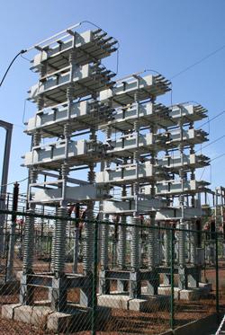
Sometimes, passing down the street, you can see that the glass of balconies are covered with an inside shiny thin film. This film is seized from defective electrical capacitors installed with certain targets on the supply powerful consumers of electrical energy distribution substations. Condenser is a typical consumer of reactive power. Unlike consumers of active power, where the main element of the design is a certain electricity material (tungsten conductor in incandescent lamps, nichrome spiral in the electric stove, etc.). In the condenser, the main element is not conductive electricity (Thin polymer film or oil-soaked paper).
Reactive capacitive power
Beautiful shiny films that you saw on the balcony are a capacitor of a conductive thin material. The condenser is remarkable by the fact that it can accumulate electrical energy, and then give it - a peculiar such battery. If you enable a capacitor to the network direct currentIt charges a short-term current pulse, and then the current will not flow through it. You can return the capacitor to the initial state by turning it off from the voltage source and connecting the load to it. For some time, the electric current will flow through the load, and the perfect capacitor is in the load exactly so much electrical energy as he received when charging. A light bulb connected to the condenser terminals may flash, the electric resistor is heated, and a careless person can "rock" or even kill with sufficient voltage on the outputs and stored amounts of electricity.
An interesting picture is obtained when connecting a condenser to a source of alternating electric voltage. Since the source of alternating voltage is constantly changing the polarity and instantaneous voltage value (in the home power grid under the law close to sinusoidal). The capacitor will be continuously charged and discharged, alternating current will continuously flow through it. But this current will not match the phase with voltage of the source of alternating voltage, and will be ahead of it 90 °, i.e. A quarter of the period.
This will lead to the fact that the total half of the variable voltage period condenser consumes energy from the network, and half the period gives, while the total consumed active electric power equal to zero. But, since a significant current flows through the capacitor, which can be measured as an ammeter, it is customary to say that the condenser is a consumer of reactive electrical power.
The reactive power is calculated as the product of the current to the voltage, but the unit of measurement is no longer watts, but a volt-amper reactive (VA). Thus, through a capacity connected to the network 220 in a frequency of 50 Hz, an electrical capacitor with a capacity of 4 microfamies flows the current of about 0.3 A. This means that the capacitor consumes 0.3 x 220 \u003d 66 (Var) reactive power - comparable with the power of the average incandescent bulb, But the condenser, unlike the lamp, does not shine and does not heat.
Reactive inductive power
If the current is ahead of the voltage in the capacitor, then whether consumers exist where the current lags behind the voltage? Yes, and such consumers, in contrast to capacitive consumers, are called inductive, remaining at the same time consumers of reactive energy. A typical inductive electric load is a coil with a certain amount of turns of a well-conductive wire, wound on a closed core from a special magnetic material.
In practice, a good approximation of a purely inductive load is a transformer (or voltage stabilizer with an autotransformer). A well-designed transformer at idle consumes very little active power, consuming power mainly reactive.
Real electrical energy consumers and complete electrical power
From consideration of the characteristics of the capacitive and inductive load, an interesting question arises - what will happen if the capacitive and inductive load is included simultaneously and in parallel. Due to their opposite reaction to the applied voltage, these two reactions will start compensate each other. The total load will be only capacitive or inductive, and in some ideal case will be able to achieve full compensation. It will look like it will be paradoxical - the connected ammeters will fix significant (and equal!) Currents through the capacitor and the inductor coil, and the total lack of current in the common chain uniting them. The described picture is somewhat violated only by the fact that there are no ideal capacitors and inductor coils, but such idealization helps to understand the essence of the processes occurring.
Let's go back to real consumers of electrical energy. In everyday life we \u200b\u200buse mainly consumers of purely active power (examples are given above), and mixed active-inductive. These are electric drills, perforators, electric motors of refrigerators, washing machines and other household appliances. These include electrical transformers of food sources of household radio electronic equipment and voltage stabilizers. In the case of a similar mixed load, in addition to active (useful) power, the load consumes also reactive power, as a result, the total power refuses more active power. Complete power is measured in a volt-ampere (BA), and is always a product of current in the load on the load voltage.
Mysterious "Kosinus FI"
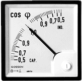 The ratio of active power to the full is called in the electrical engineering "Kosinus FI". Denotes cos φ. This ratio is also called the power factor. It is easy to see that for the case of a purely active load, where complete power coincides with the active, Cos φ \u003d 1. For cases of pure capacitive or inductive loads, where the active power is zero, cos φ \u003d 0.
In the case of a mixed load, the value of the power factor is in the range from 0 to 1. For household appliances, usually in the range of 0.5-0.9. On average, it can be considered equal to 0.7, a more accurate value is indicated in the passport of the electrical appliance.
What do we pay?
And finally, the most interesting question is for what kind of energy the consumer pays. Based on the fact that the reactive component of total energy does not bring any benefit to the consumer, and the share of the period reactive energy is consumed, and the share is given, it is not necessary to pay for reactive power. But the demon, as you know, lies in the details. Since the mixed load increases the current on the network, problems occur on power plants, where electricity is generated by synchronous generators, namely: the inductive load "places" the generator, and bringing it to the previous state to the costs of already real active power on its "Advisitating".
Thus, to force the consumer to pay for consumed reactive inductive power is quite fair. This encourages the consumer to compensate for the reactive component of its load, and since this component is mainly inductive, compensation is to connect capacitors in advance of the calculated container.
The consumer finds the opportunity to pay less
If the consumer has to pay separately for consumed active and reactive power. He is ready to go for additional costs and establish a capacitor battery at its enterprise, including strictly on schedule, depending on the average statistics of electricity consumption by day of day.
There is also the ability to install special devices (reactive power compensators), connecting capacitors automatically depending on the size and nature of the power consumed at the moment. These compensators allow you to raise the value of the power coefficient from 0.6 to 0.97, i.e. Almost to one.
It is also assumed that if the ratio of consumed reactive energy and general does not exceed 0.15, then the corporate consumer is released from paying for reactive energy.
As for individual consumers, in view of the relatively low power consumed by their power, to share accounts for the payment of electricity consumed to the active and reactive is not accepted. Household electrical energy take into account only active power electric loadFor it and an invoice for payment is set. Those. Currently, there is not even a technical ability to put an individual consumer account for consumed reactive power.
There are no special incentives to compensate for the inductive component of the consumer, and it is difficult to implement technically. Constantly connected capacitors when the inductive load is disconnected will be useless to load the supply wiring. For the electric member (before the counter, too, but for that the consumer does not pay), which will cause consumption of active power with an appropriate increase in payment for payment, and automatic compensators of the road and hardly justify the costs of their acquisition.
Another thing is that the manufacturer sometimes establishes compensatory capacitors at the input of consumers with the inductive component of the load. These capacitors, with their proper selection, slightly reduce energy losses in the supply wires, while slightly increase the voltage on the connected electrical appliance by reducing the voltage drop on the supply wires.
But, most importantly, the compensation of reactive energy from each consumer, from the apartment to a huge enterprise, will reduce currents in all power supply lines, from the power station to the apartment panel. Due to the reactive component of the total current, which will reduce energy loss in the lines and increase the efficiency of electrical systems.
The calculation of the electrical energy used by the household or industrial electrical device is usually made taking into account full currentThring through the measured at the same time two indicators are distinguished, reflecting the costs of complete power when servicing the consumer. These indicators are active and reactive energy. Complete power is the sum of these two indicators. About what is active and reactive electricity and how to check the amount of accrued payments, try to tell in this article.
Full power
Under current practice, consumers pay no useful power, which is directly used in the farm, and the full, which the enterprise releases is released. Distinguish these indicators for measurement units - complete power is measured in Volt-amperes (BA), and useful - in kilowatts. Active and reactive electricity is used by all electrical appliances driven.
Active electricity
The active component of full capacity makes a useful work and is converted into those types of energy that the consumer needs. Part of household and industrial electrical appliances in the calculations are active and complete power coincide. Among such devices - electric stoves, incandescent bulbs, electric furnaces, heaters, irons and ironing presses etc.
If the passport shows the active power of 1 kW, then the complete power of such a device will be 1 kVA.
The concept of reactive electricity
This type of electricity is inherent in chains, which contains jet elements. Reactive electricity is part of a complete inclined power that is not spent on the useful work.
There is no concept in the electrical caps of DC. In chains, the reactive component occurs only if there is an inductive or capacitive load. In this case, the inconsistency of the current phase from the voltage phase is observed. This phase shift between voltage and current is denoted by the symbol "φ".
In the inductive load in the chain, the phase lag is observed, with a capacitive - its advance. Therefore, only part of the total power comes to the consumer, and the main losses occur due to the useless heating of devices and devices during operation.
Power loss occur due to the presence of inductive coils and capacitors in electrical devices. Because of them, electricity is accumulated in the chain for some time. After that, the stored energy arrives back into the chain. To the instruments, which contains a reactive component of electricity, includes portable power tools, electric motors and various household appliances. This value is calculated taking into account the special coefficient of power, which is denoted as Cos φ. 
Calculation of reactive electricity
The power factor lies in the range from 0.5 to 0.9; The exact value of this parameter can be found from the drive passport. Complete power must be defined as a private from dividing active power to the coefficient.
For example, if in the passport of the electrical drill, the power of 600 W and the value of 0.6, then the device consumed complete power will be equal to 600/06, that is, 1000 VA. In the absence of passports to calculate the full power of the device, the coefficient can be taken equal to 0.7.
Since one of the main tasks of acting is the delivery of the useful power to the final consumer, the reactive loss of electricity is considered a negative factor, and the increase in this indicator questioned the effectiveness of the electrocipation as a whole. The balance of active and reactive power in the chain can be clearly represented in the form of this fun drawing: 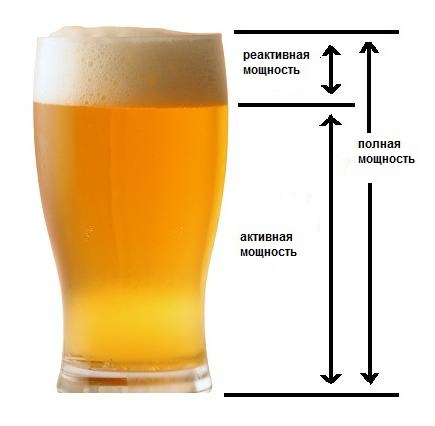
The value of the coefficient when taking into account losses
The higher the value of the power factor, the less will the loss of active electricity - and therefore the end consumer consumed electrical energy will cost a little cheaper. In order to increase the importance of this coefficient, various techniques compensation for non-target electricity losses are used in electrical engineering. Compensating devices are an advanced current generators that smoothes the phase shift angle between the current and voltage. For the same purpose, capacitors are sometimes used. They are connected in parallel to the working chain and are used as synchronous compensators. 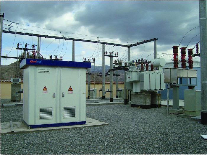
Calculation of the cost of electricity for private clients
For individual use, active and reactive electricity in accounts is not divided - on the scale of consumption, the proportion of reactive energy is small. Therefore, private clients in power consumption up to 63 are paying one account, in which all electricity consumed is considered active. Additional losses in the chain on the reactive electricity are not separately allocated and not paid.
Accounting for reactive electricity for enterprises
Another thing is enterprises and organizations. In industrial premises and industrial workshops, a huge number of electrical equipment has been established, and in the total transmitted electricity there is a significant part of the energy of the reactive, which is necessary for the operation of power supplies and electric motors. Active and reactive electricity supplied to enterprises and organizations, needs a clear separation and other way to pay for it. The basis for the regulation of relations of the enterprise-supplier of electricity and end users in this case is a typical treaty. According to the rules established in this document, organizations that consume electricity over 63 A need a special device that provides indications of reactive energy for accounting and payment.
The network enterprise sets the reactive electricity meter and charges payment according to its testimony. 
Reactive energy coefficient
As mentioned earlier, active and reactive electricity in payment accounts are allocated by separate lines. If the ratio of the volume of reactive and consumed electricity does not exceed the established norm, the fee for reactive energy is not accrued. The ratio coefficient is registered in different ways, its average value is 0.15. If this threshold is exceeded, the consumer enterprise is recommended to install compensatory devices.
Reactive energy in apartment buildings
A typical consumer of electricity is an apartment building with the main fuse that consists of electricity over 63 A. If there are exclusively residential premises in such a house, the reactive electricity fee is not charged. Thus, the tenants of an apartment building see in charges only for full electricity supplied to the house of the enterprise-supplier. The same norm concerns housing cooperatives.
Private accounting cases of reactive power
There are cases when multi-storey building There are also commercial organizations, and apartments. Delivery of electricity to such houses is regulated by individual acts. For example, the division can serve as the size of the useful area. If in apartment house Commercial organizations occupy less than half of the useful area, the payment for reactive energy is not charged. If the threshold percentage was exceeded, the obligations of payment for reactive electricity arise.
In some cases, residential buildings are not exempt from paying for reactive energy. For example, if the house has an elevator connection points for apartments, accrual for the use of reactive electricity occurs separately, only for this equipment. Owners of apartments are still paying only active electricity. 
Understanding the essence of active and reactive energy makes it possible to competently calculate the economic effect of the installation of various compensation devices that reduce the loss from the reactive load. According to statistics, such devices allow you to raise Cos φ from 0.6 to 0.97. Thus, automatic compensatory devices help to save up to a third of the electricity consumer provided. A significant decrease in thermal losses increases the life of instruments and mechanisms at production sites and reduces the cost of finished products.


