Definitions and formulas
Power is the work produced per unit of time. Electrical power is equal to the current of the voltage: P \u003d U ∙ i. From here you can withdraw other power formulas:
P \u003d R ∙ i ∙ i \u003d r ∙ i ^ 2;
P \u003d U ∙ U / R \u003d U ^ 2 / R.
We obtain the power measurement unit, substituting the voltage and current measurement unit in the formula:
[P] \u003d 1 B ∙ 1 A \u003d 1 BA.
The unit of measurement of electrical power equal to 1 v is called Vat (W). The name of the Volt-ampere (BA) is used in the technique alternating current, but only for measuring full and re active power.
Units of measurement of electrical and mechanical power are associated with the following ratios:
1 W \u003d 1 / 9.81 kg m / s ≈1 / 10 kg m / s;
1 kg m / s \u003d 9.81 W ≈10 W;
1 hp \u003d 75 kg m / s \u003d 736 W;
1 kW \u003d 102 kg m / s \u003d 1.36 hp
If you do not consider inevitable energy losses, then the engine with a capacity of 1 kW can pump every second 102 liters of water to a height of 1 m or 10.2 liters of water to a height of 10 m.
Electric power .
Examples
1. The heating element of the electric furnace to the power of 500 W and voltage 220 V is made of high resistance wire. Calculate the resistance of the element and the current that passes through it (Fig. 1).
Current will find by the formula of the electrical power P \u003d U ∙ i,
where i \u003d p / u \u003d (500 bm) / (220 b) \u003d 2.27 A.
Resistance is calculated by another power formula: P \u003d U ^ 2 / R,
where r \u003d u ^ 2 / p \u003d (220 ^ 2) / 500 \u003d 48400/500 \u003d 96,8400 / 500 \u003d 96.8 ohms.
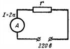
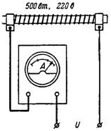
Fig. one.
2. What resistance should have a spiral (Fig. 2) tiles at a current 3 a and power of 500 W?
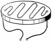
Fig. 2.
For this case, we apply another power formula: P \u003d U ∙ i \u003d R ∙ i ∙ i \u003d R ∙ i ^ 2;
hence R \u003d P / I ^ 2 \u003d 500/3 ^ 2 \u003d 500/9 \u003d 55.5 Ohm.
3. What power turns into heat at the resistance r \u003d 100 ohms, which is connected to the voltage network U \u003d 220 V (Fig. 3)?
P \u003d U ^ 2 / R \u003d 220 ^ 2/100 \u003d 48400/100 \u003d 484 W.
Fig. 3.
4. In the scheme in Fig. 4 ammeter shows the current i \u003d 2 A. Calculate the resistance of the consumer and the electrical power consumed in the resistance r \u003d 100 ohms when it is turned on into the network by the voltage U \u003d 220 V.
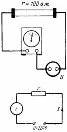
Fig. four.
r \u003d u / i \u003d 220/2 \u003d 110 ohms;
P \u003d U ∙ i \u003d 220 ∙ 2 \u003d 440 W, or P \u003d U ^ 2 / R \u003d 220 ^ 2/110 \u003d 440 W.
5. Only its rated voltage is indicated on the lamp to determine the rest of the lamp data, we collect the circuit shown in Fig. 5. Adjust the flow of the current so that the voltmeter connected to the lamp clamps showed the voltage Ul \u003d 24 V. Ampmeter shows the current i \u003d 1.46 A. What power and resistance has a lamp and what voltage loss and power occur on the rheostat?
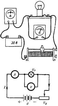
Fig. five.
The power of the lamp p \u003d Ul ∙ i \u003d 24 ∙ 1,46 \u003d 35 W.
Its resistance is RL \u003d UR / I \u003d 24/146 \u003d 16.4 Ohm.
The voltage drop on the row of UR \u003d U-Ul \u003d 30-24 \u003d 6 V.
Power loss in the PP \u003d UR ∙ i \u003d 6 ∙ 1,46 \u003d 8.76 W.
6. On the electric furnace panel, its nominal data is indicated (p \u003d 10 kW; u \u003d 220 V).
Determine which resistance is a furnace and which current passes through it when P \u003d U ∙ i \u003d U ^ 2 / R;
r \u003d U ^ 2 / p \u003d 220 ^ 2/10000 \u003d 48400/10000 \u003d 4.84 ohms; I \u003d p / u \u003d 10,000 / 220 \u003d 45.45 A.
Fig. 6.
7. What is the voltage U on the generator clamps, if at a current 110 and its power is 12 kW (Fig. 7)?
Since p \u003d u ∙ i, then u \u003d p / i \u003d 12000/110 \u003d 109 V.
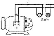
Fig. 7.
8. On the diagram in Fig. 8 shows the operation of electromagnetic current protection. With a certain current, the electromagnet EM, which is held with the spring P, will attract anchor, the contact will open the contact to and tear the current circuit. In our example, the current protection breaks the current circuit at a current I≥2 A. How many lamps of 25 W can be simultaneously incorporated at the voltage of the network U \u003d 220V, so that the limiter does not work?
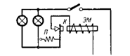
Fig. eight.
Protection is triggered at i \u003d 2 A, i.e., at the power P \u003d U ∙ i \u003d 220 ∙ 2 \u003d 440 W.
Dividing the total power of one lamp, we obtain: 440/25 \u003d 17.6.
At the same time, 17 lamps can burn.
9. The electric furnace has three heating elements to the power of 500 W and voltage 220 V connected in parallel.
What are the overall resistance, current and power when working oven (Fig. 91)?
The total power of the furnace p \u003d 3 ∙ 500 W \u003d 1.5 kW.
The resulting current i \u003d p / u \u003d 1500/220 \u003d 6.82 A.
The resulting resistance r \u003d u / i \u003d 220 / 6.82 \u003d 32.2 ohms.
Current of one element I1 \u003d 500/220 \u003d 2.27 A.
Resistance of one element: R1 \u003d 220 / 2.27 \u003d 96.9 Ohm.
Fig. nine.
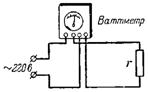
Fig. 10.
Since P \u003d U ^ 2 / R, then R \u003d U ^ 2 / p \u003d 48400/75 \u003d 645.3 ohms.
Current i \u003d p / u \u003d 75/220 \u003d 0.34 A.
11. The dam has a drop of water levels H \u003d 4 m. Each second through the pipeline on the turbine is 51 liters of water. What mechanical power turns into an electrical generator, if you do not consider losses (Fig. 11)?
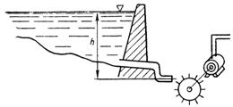
Fig. eleven.
MECHANICAL POWER PM \u003d Q ∙ H \u003d 51 kg / s ∙ 4 m \u003d 204 kg m / s.
From here electric power PE \u003d PM: 102 \u003d 204: 102 \u003d 2 kW.
12. What power should have a pump engine pumping every second of 25.5 liters of water from a depth of 5 m to the tank located at the height of the Z M? Losses are not taken into account (Fig. 12).
Fig. 12.
The total height of water lifting H \u003d 5 + 3 \u003d 8 m.
Machine power PM \u003d Q ∙ H \u003d 25.5 ∙ 8 \u003d 204 kg m / s.
Electric power PE \u003d PM: 102 \u003d 204: 102 \u003d 2 kW.
13. Gets from a reservoir to one turbine every second of 4 m3 of water. The difference between water levels in the reservoir and the turbine H \u003d 20 m. Determine the power of one turbine excluding losses (Fig. 13).
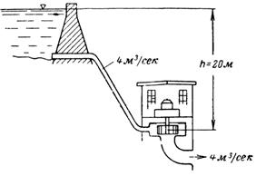
Fig. 13.
Mechanical power of the flowing water PM \u003d Q ∙ H \u003d 4 ∙ 20 \u003d 80 t / s m; PM \u003d 80000 kg m / s.
The electrical power of one turbine PE \u003d PM: 102 \u003d 80000: 102 \u003d 784 kW.
14. In Engine direct current With parallel excitation, the anchor winding and the excitation winding are connected in parallel. Anchor winding has a resistance r \u003d 0.1 Ohm, and an anchor current I \u003d 20 A. The excitation winding has the resistance of RV \u003d 25 Ohm, and the excitation current is equal to i \u003d 1.2 A. What power is lost in both engine windings (Fig. 14 )?
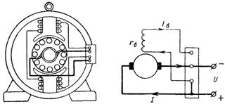
Fig. fourteen.
Power loss in the winding of the anchor P \u003d R ∙ i ^ 2 \u003d 0.1 ∙ 20 ^ 2 \u003d 40 W.
Power loss in excitation winding
PV \u003d RV ∙ I ^ 2 \u003d 25 ∙ 1.2 ^ 2 \u003d 36 W.
Common losses in the windings of the engine P + PV \u003d 40 + 36 \u003d 76 W.
15. The electrolycove on the voltage 220 V has four switchable heating steps, which is achieved by various inclusions of two heating elements with resistances R1 and R2, as shown in Fig. fifteen.
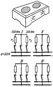
Fig. fifteen.
Determine the resistance R1 and R2 if the first heating element has a power of 500 W, and the second 300 W.
Since the power secreted in the resistance is expressed by the formula P \u003d U ∙ i \u003d U ^ 2 / R, then the resistance of the first heating element
r1 \u003d U ^ 2 / p1 \u003d 220 ^ 2/500 \u003d 48400/500 \u003d 96.8 Ohm,
a second heating element R2 \u003d U ^ 2 / p2 \u003d 220 ^ 2/300 \u003d 48400/300 \u003d 161.3 Ohm.
In the status of the stage of the resistance, the resistance is connected sequentially. The power of the electric shield in this position is:
P3 \u003d U ^ 2 / (R1 + R2) \u003d 220 ^ 2 / (96.8 + 161.3) \u003d 48400 / 258.1 \u003d 187.5 W.
In the position of the stage I, the heating elements are connected in parallel and the resulting resistance is: R \u003d (R1 ∙ R2) / (R1 + R2) \u003d (96.8 ∙ 161.3) / (96,8 + 161.3) \u003d 60.4 Ohm.
Tile power in the stage of the stage I: P1 \u003d U ^ 2 / R \u003d 48400 / 60.4 \u003d 800 W.
We obtain the same power by folding the power of individual heating elements.
16. The lamp with tungsten thread is calculated for the power of 40 W and voltage of 220 V. What resistance and current have a lamp in the cold condition and at operating temperatures 2500 ° C?
The power of the lamp p \u003d U ∙ i \u003d U ^ 2 / r.
Hence the thread resistance of the lamp in the hot state RT \u003d U ^ 2 / p \u003d 220 ^ 2/40 \u003d 1210 Ω.
The resistance of the cold thread (at 20 ° C) we define according to the formula Rt \u003d R ∙ (1 + α ∙ Δt),
from R \u003d RT / (1 + α ∙ Δt) \u003d 1210 / (1 + 0.004 ∙ (2500-20)) \u003d 1210 / 10.92 \u003d 118 ohms.
The thread of the lamp in the hot state passes the current i \u003d p / u \u003d 40/20 \u003d 0.18 A.
The current when turned on is: i \u003d u / r \u003d 220/118 \u003d 1.86 A.
When turning on the current about 10 times more than a hot lamp current.
17. What are the loss of voltage and power in the copper contact wire electrified railway (Fig. 16)?
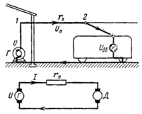
Fig. sixteen.
The wire has a cross section of 95 mm2. The electric train motor consumes the current 300 A at a distance of 1.5 km from the current source.
Loss (drop) of voltage in line between points 1 and 2 UP \u003d I ∙ RP.
The resistance of the contact wire RP \u003d (ρ ∙ L) / s \u003d 0.0178 ∙ 1500/95 \u003d 0.281 ohms.
The voltage drop in the contact wire UP \u003d 300 ∙ 0.281 \u003d 84.3 V.
The voltage of the UD on the engine clamps will be 84.3 to less than the voltage U at the source clips.
The voltage drop in the contact wire during the movement of the electric train changes. The further the electric train is removed from the current source, the longer the line, and therefore more its resistance and the voltage drop in it. The current on the rails is returned to the grounded source of the resistance of rails and the Earth is almost equal to zero.
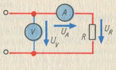
Quite often, there is a need to measure the power consumed from the network, or the network generated. This is necessary to take into account consumed or generated energy, as well as to ensure normal operation of the power system (avoiding overload). You can measure power in several ways - direct and indirect. With direct dimension, the wattmeter is used, and with an indirect ammeter and voltmeter.
Power measurement in DC circuit
Due to the lack of reactive and active component in the DC circuits to measure the batter, the wattmeter is used very rarely. As a rule, the value of consumed or disconnected energy is measured with an indirect method, using the current I in the circuit, and using the load voltage u are measured. After that, by applying a simple formula P \u003d UI and the power value is obtained.
To reduce due to the effects of internal resistances of devices, the devices can be connected via various schemes, namely, with a relatively small load resistance R, the inclusion scheme is used:
And with a large value of R such a scheme:
Measurement of power in alternating current single-phase circuits
The main difference of alternating current circuits from DC networks, perhaps, is that there are several capacities in alternating voltage - . The complete measurement is often the same indirect method using an ammeter and a voltmeter and its value equal to S \u003d UI.
Measuring the same active p \u003d uicosφ and reactive q \u003d uisinφ is made by a direct method using a wattmeter. To measure the wattmeter in the chain are connected by the following scheme:
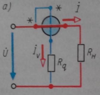
Where the current winding must be connected sequentially with the load R N, and, accordingly, the voltage winding parallel to the load.
Measurement of reactive power in single-phase networks is not performed. Such experiments are often set only in laboratories, where wattmeters include according to special schemes.
Power measurement in three-phase AC circuits
As in single-phase networks, and in three-phase, the total energy of the network can be measured with an indirect method, that is, using a voltmeter and an ammeter according to the schemes shown above. If the load of the three-phase chain is symmetrical, then you can apply such a formula:
U L - voltage linear, I- phase current.
If the phase load is not symmetrical, then the capacities are summarized from the phases:
![]()
When measuring active energy in a four-wire chain when using three wattmeters, as shown below:
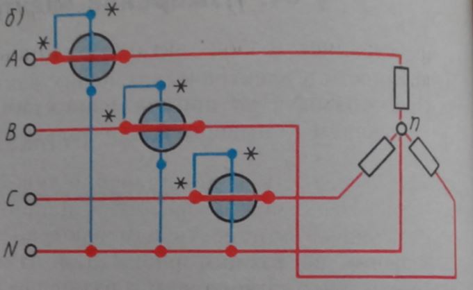
The total energy consumed from the network will be the amount of wattmeter readings:
Not less distribution and method of measuring two wattmeters (applicable for three-wire chains only):
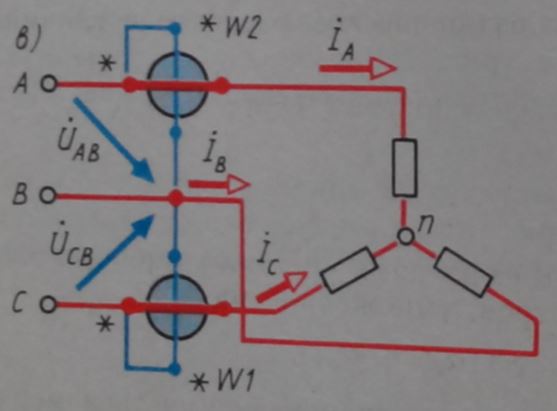
The amount of their indications can be expressed by the following expression:
With a symmetric load, the same formula is applicable as for full energy:
![]()
Where φ is a shift between the current and voltage (the angle of the phase shift).
The measurement of the reactive component is made by the same scheme (see Figure B)) and in this case it will be equal to the difference in algebraic between instrument indicators:
![]()
If the network is not symmetrical, two or three wattmeters are used to measure the reactive component, which are connected according to various schemes.
The process of measuring active and reactive power
Make measurements of the active power of the circuit of alternating voltage. They are connected according to the same schemes as wattmeters. Accounting for reactive energy in single-phase consumers is not conducted in our country. Its accounting is produced in three-phase chains large industrial enterprises that consume large amounts of electricity. Active energy meters have labeling CA, reactive Wed. Electronic electricity meters are also widely used.
Crystal cell
Electricity. All metals are conductors electric current. They consist of spatial crystal latticewhose nodes coincide with the centers of positive ions. Free electrons are chaotically moving around the ions.
In metals electronic conductivity
Electric current in metals is called an ordered movement of free electrons.For the direction of current take the direction of movementpositively charged particles.
Electrical charges can move ordered under action electric field, so condition for the existence of email. Current is the presence of an electric field and free email carriers.
The strength of the current is numerically equal to the charge flowing through this transverse cross section of the conductor per unit of time. The current is called constant, e if the strength of the current and its direction does not change over time.
1 amp (a) equal to power DC, in which, through any cross-section of the conductor for 1 s flows 1 cell electricity. I. = q. 0 nVS. Current stream in chains are measured. Conditional designation in the chain
Work and current power. Electric current supplies us with energy. It occurs due to the work of the electric field to move free charges in the conductor. Consider a section of the chain by which the current flows I. Voltage on the plot we denote U., the resistance of the site is R. When current flows over a homogeneous section of the chain, the electric field makes a job. During Δ.t. Chapted ChargeΔ q. = I. Δ t. . Electric field On the highlighted area makes work.ΔA. = U. I. Δ t. — This work is calledelectrical current operation . Due to the work on the site under consideration can be committed mechanical work; can also leak chemical reactions. If this is not, then the operation of emailpins only leads to the heating of the conductor. The current is equal to the amount of heat released by the conductor with the current:— joule Law - Lenza
Electric current power equal to current operation ΔA. By time interval Δ t.for which this work was performed on this site: P \u003d IU. or . Electric current in si is expressed in joules (J.), power - in watts. (T.).
Ohm law for a closed chain.
The current source has EMF () and resistance ( r.
), called internal. The electromotive force (EMF) is called the ratio of the work of third-party charges for the movement of charge q.
Along the chain, to the meaning of this charge ( 1B \u003d 1J / 1kl). Consider now closed (full) DC chain consisting of a source with electromotive power and internal resistance r.
and external uniform plot With resistance R.
. (R + R
) - Full chain resistance. Ohm's law for the total chain is recorded as ![]() or
or
One of the parameters characterizing the behavior of electrons in the electrical circuit, except for voltage and current, performs power. It is a measure of the amount of work that can be performed per unit of time. Work is usually compared with weight lifting. The more weight and height of its lifting, the more work is done. Power determines the speed of the unit of work.
Units
The power of cars is calculated in the horsepower - a unit of measurement invented by the manufacturers of steam engines in order to measure the performance of their aggregates in the usual energy source of that time. The power of the car does not say how high it can come to the hill or how much weight it can carry, but only shows how quickly he will do it.
The engine power depends on its speed and the torque of the output shaft. Speed \u200b\u200bis measured in revolutions per minute. The torque is the moment of the power of the engine, which was measured originally in the pound feet, and now in Newton meters or Joules.
Tractor motor 100 liters. from. Rotate slowly, but with a large torque. Motorcycle motor equal power rotates quickly, but with a small torque. The capacity calculation equation is:
P \u003d 2π s T / 33000, where S is the rotational speed, rpm, and T is the moment of rotation.
Variables here are the moment and speed. In other words, the power is directly proportional to ST: P ~ ST.
DC power
In the electrkets, the power is in functional dependence on voltage and current. It is not surprising that it is similar to the above equation P \u003d IU.
But here P is not proportional to the current multiplied by the voltage, but equals him. It is calculated in watts, abbreviated W.
It is important to know that current and voltage separately the power is not determined, only their totality. The voltage is the work per unit of electrical charge, and the current is the speed of charges of charges. The voltage (equivalent of the work) is similar to work when lifting weight in countering gravity strength. Current (equivalent speed) is similar to weight lifting speed. Their work is power.
As tractor and motorcycle engines, a high voltage chain and a small current is capable of being the same power with a chain of low voltage and a high current. Voltage and current outside the relationship cannot characterize the power of electrocups.
The open circuit with the voltage and zero power of the current operation does not make, regardless of the height of the voltage. After all, according to the formula, anywhere, multiplied by 0, gives 0: p \u003d 0 u \u003d 0. In the closed chain from the superconducting wire with zero resistance Current can be achieved at a voltage equal to zero, which will also not lead to dispersion of the energy: p \u003d i 0 \u003d 0.
Horsepower and watts indicate the same thing: the amount of work that can be done per unit of time. These units are interconnected by the ratio
1 l. from. \u003d 745.7 W.
Example of calculation
So, the power of the electric pump in watts is equal to the voltage to the current.
To determine, for example, the load capacity of 3 ohm resistance, in the circuit with a power battery with a voltage of 12 V, it is necessary, applying the Ohm law, to find the current
I \u003d u / r \u003d 12/3 \u003d 4 a
Multiplying the strength of the current for voltage and will give the desired result:
P \u003d I U \u003d 4 A 12 V \u003d 48 W
Thus, the lamp consumes 48 W.
What happens while increasing the voltage?
At a voltage of 24 V and resistance of 3 ohm current
I \u003d u / r \u003d 24/3 \u003d 8 a
When doubling the voltage doubled the strength of the current.
P \u003d IU \u003d 8 A 24 V \u003d 192 W
Power also increased, but more. Why? Because it is a function of the product of voltage to the current, the voltage and current increased by 2 times, therefore, the power increased 4 times. This can be checked by a division of 192 watts by 48, the private from which is 4.
Options of formula
By applying an algebra to convert formula, you can take the original equation and convert it to cases when one of the parameters is unknown.
If voltage and resistance are given:
P \u003d (u / r) u or p \u003d u 2 / r
With the well-known current and resistance:
P \u003d i (i r) or p \u003d i 2 r
Historical fact: the relationship between the dispersed capacity and power of current through the resistance was opened by James Prescott Joule, and not Georg Simon Ohm. It was published in 1841 in the form of the equation p \u003d i 2 R and is called the Joule-Lenza law.
Power equations:
- P \u003d u i
- P \u003d i 2 R
- P \u003d U 2 / R
Alternating current
Ohm and Joule-Lenza law were installed for DC, but they are also valid for instant values \u200b\u200bof changing current and voltage.
The instantaneous value p is equal to the product of instantaneous values \u200b\u200bof current and voltage strength, taking into account their displacement by phase to the angle φ:
P (t) \u003d u (t) i (t) \u003d u m cosωt i m cos (ωt-φ) \u003d (1/2) u m i m cosφ + (1/2) u m i m cos (2ωt- φ).
It follows from the equation that instantaneous power has a constant component, and it makes oscillatory movements around the average value with a frequency that is twice as much as the current frequency.
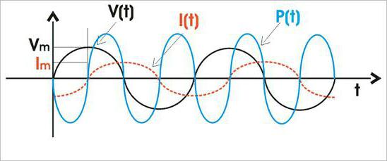
The average value of P (T), which is practical interest, is:
P \u003d (u m i m / 2) cosφ
Taking into account the fact that cos φ \u003d r / z, where Z \u003d (R 2 + (ωl - 1 / ω c) 2) 1/2 and u m / z \u003d i m,
Here i \u003d i m 2 -1/2 \u003d 0.707 i m is the effective value of the strength of the current, A.
Similarly, u \u003d u m 2 -1/2 \u003d 0.707 U M is an efficient stress, V.
The average power through efficient voltage and current is determined.
P \u003d u i cos φ, where cos φ is the power factor.
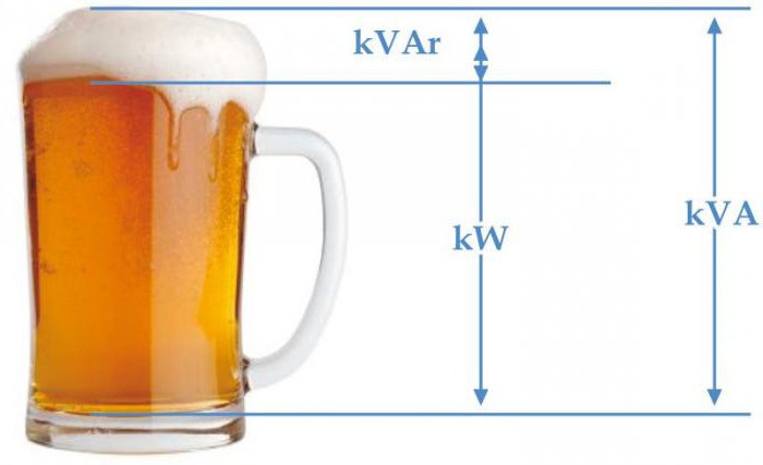
P The electrocuprup goes into a thermal or other type of energy. The greatest active power can be achieved at cosφ \u003d 1, that is, in the absence of a phase shift. She is called full power
S \u003d u i \u003d z i 2 \u003d u 2 / z
Its dimension coincides with the dimension P, but with the purpose of distinguishing S is measured by volt-amperes, VA.
The degree of energy intensity in electrocups is characterized by reactive power
Q \u003d u i sinφ \u003d u i p \u003d u p i \u003d x i 2 \u003d u 2 / x
It has a dimension of active and complete, but for the purpose of distinguishing it expresses with volt-amperes by reactive, var.
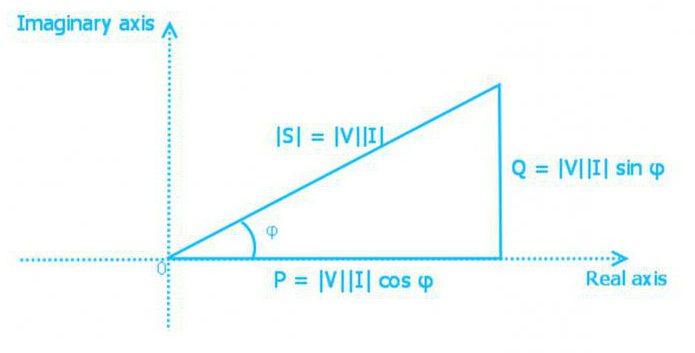
Triangle capacity
The power is active, reactive and complete interconnected by expression
S \u003d (P 2 + Q 2) 1/2
Power is represented as a side of a rectangular triangle. Using the laws of trigonometry, one can find the length of one side (the amount of power of any type) along the two known sides or along the length of one and the corner. In such a triangle, active power is adjacent cathet, reactive - opposite, and complete power - hypotenurus. The angle between the active power or hypothenuclear or hypothenoose is equal to the corner of the impedance phase z of the electrical circuit.
The comprehensive form of recording this relationship is as follows:
S \u003d p + jq \u003d u i cosφ + j u i sinφ \u003d u i e jφ \u003d u i * where
S - complex power;
I * - complex conjugate current value.
The real component of the complex is active, and the imaginary is reactive.
Instant full power always remains permanent.
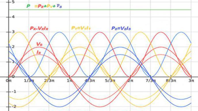
Three-phase current power
The load of each phase of three-phase electrocups converts energy or exchange it with a power source. As a consequence, P and Q circuits are equal to the total power of all phases:
P \u003d p r + p y + p b; Q \u003d Q R + Q Y + Q B - the "Star" connection;
P \u003d p Ry + p yb + p br; Q \u003d Q Ry + Q YB + Q Br - Connection "Triangle".
The active and reactive power of each phase are defined as in a single-phase chain.
Complete power of the three-phase chain:
S \u003d (P 2 + Q 2) 1/2,
that in a comprehensive form has the form
S \u003d p + jq \u003d (p r + p y + p b) + j (q r + q y + q b) \u003d s r + s y + s b \u003d u r i r + u y i y + u b I B.
Symmetric phase load has a consequence of equality of their capacities. That is why the power of the current is equal to the tripled active and reactive phase power:
P \u003d 3p Φ \u003d 3 i f u f cosφ f \u003d 3 r f i f 2
Q \u003d 3 q Φ \u003d 3 i f u f sinφ Φ \u003d 3 x F i f 2
S \u003d 3 s f \u003d 3 i f u f
I f and u f here can be replaced by their linear values, given that for the star u f \u003d u l; I f \u003d i l, and for a triangle u f \u003d u l; I f \u003d i l 3 -1/2:
P \u003d 3 1/2 i l u l cosφ f;
Q \u003d 3 1/2 i l u l sinφ f;
S \u003d 3 1/2 I l u l.
Current of nonsenseoidal form
The definition P in the inconsection circuit is similar to its definition in the sinusoidal current circuit, since the average instantaneous power for the period t
P \u003d 1 / T∫u i dt
The active power of the current is determined by the sum of the harmonic components, including a constant, which is a harmonic of zero frequency.
The reactive current of the current is similarly the result of the addition of Q of each harmonic.
Q \u003d Σu k i k sinφ k \u003d σ q k
DC Operation and Power
The passage of electrical current on the conductor is associated with the cost, a certain amount of energy. Measure of the amount of energy spent per unit of time is power:
P \u003d.A /t.
where P is power; A - the amount of energy spent (work) during T.
According to this formula
A \u003d Pt.
it is possible to calculate the cost of energy in order to determine the cost of operating electrical equipment.
The power in the DC electrical circuit is uniquely associated with the resistance of this chain and the current passing through it:
P \u003d i 2 r (3-12)
where I is current, R is resistance.
Making substitutions using the law, Ohm, you can also get:
P \u003d UI. (3-12a)
and
P \u003d U 2 / R (3-12B)
where U is the voltage at the ends of the chain with the resistance R.
If not the whole supplied (rpodev) to the circuit, the power is consumed in it useful (RPOL), then they talk about efficiency ratio (efficiency) chains, source, etc.
h \u003d RPOL / RPodv
As Kpd. Always less than one, then it is usually expressed as a percentage
Very important issues are the modes of using current sources in which is achieved maximum efficiency or the greatest "return".
Based on the Ohm law for the entire circuit, any real current source can be represented by an equivalent generator (Fig. 3-6, B) consisting of a series of connected alternator E with zero internal resistance and separate resistance of the RVN. By loading such an RN resistance generator, depending on the ratio of RN and RVN, you can get sharply excellent modes of operation of the current source.
If Rn \u003e\u003e RVN, then the chain impedance is almost equal to the load resistance. In this case, the change in RN changes the current in the chain, but almost does not affect the voltage, which turns out to be very close to the value of the EDC, i.e. umax \u003d e
Such a source use mode is called mode voltage generator. It is the main mode of operation of batteries and batteries. In the voltage generator mode, the efficiency is very close to 100%, however, the power given to the outer chain is small, because small currents are selected from the source.
If you take small load resistance RN< I Ma.x \u003d.E / RVN Such a regime is called the mode generator current. It is widely used in amplifiers on feeds, the internal resistance of which is usually many times higher than the load resistance. At the same time, the source efficiency is very small (percent and less units), and the power selected from the source into the outer chain is also insignificant. Finally, the third regime, widely used in diagrams with transistors, is coordination modecharacterized by equality of the load resistance to the internal resistance of the generator (RN \u003d RVN). At the same time, the stress on the load is half an emf (U \u003d 0.5 E), and the current - half of the short circuit current (i \u003d 0.5 iMax); The power, selectable by the outer chain, is maximum and equal to Rmax \u003d.E 2 / (4RVN) At the same time, the source efficiency is 50%. The maximum power of the RMA, which is capable of pumping the source in the negotiation mode, is often referred to as the disposable power of the RRASP generator.
Electric current passing through the conductor, heats it. The larger the current and the smaller with this current area of \u200b\u200bthe wire cross section, the stronger the wire heats up. In order for the heating of the instruments to the current is not very strong, the area of \u200b\u200bthe wire cross sections should be selected according to the load current. The heating of the device largely depends on its design: the better the cooling conditions, the less the device will be heated.
When calculating wires, the current density is allowed in different cases, i.e., the permissible value of the current is 1mm2 the area of \u200b\u200bthe wire cross section. In the most common cases of radio repair practices, the following limit values \u200b\u200bof the current density y are guided by:
1. For rheostats and ballast wires, performed on porcelain or ceramic frames with one layer of naked wire, Y \u003d 6-10 A / mm2. For windings of electromagnets, relays, calls designed for short-term inclusions, y \u003d 4-5 A / mm2.
3. For windings of transformers with a capacity of up to 75 W, as well as for windings of throtsels, relays and wire resistances with a multi-layer winding (for example, the resistance of the mesh displacement), designed for long-term inclusion, Y \u003d 2-3 A / mm2, the same capacity of 75- 300 W y \u003d 1.5 A / mm2.
4. For shunts and additional resistances in the measuring instrument Y<1 а/ мм2.
5. For heating devices, depending on the wire material, the design of the device and the working conditions y \u003d 8-20 A / mm2.
Determining the diameter of the wire to the specified current at a permissible current density, y produced by the formula:
where D is the required diameter of the wire, mm; - Current, and; y - current density, a / mm2.
When choosing for radio equipment, inspire resistances are guided by the capacity dissipated on the resistance during the operation of the device. Improvant resistances are available on various normally scattered capacities (0.25, 0.5, 1, 2 W or more). When the resistance is installed in the device, it is necessary to ensure that the power released in the resistance does not exceed the norm.
If there are no resistance to the necessary load at hand, then resort to a compound of several resistance, and in order not to complicate the pacepts, it is recommended to connect the same resistance.
Wire resistance designed for a smaller current than must be connected in parallel, and it is necessary to connect as many resistances, how many times the current requires less required for them. For example, if the current in the circuit is 0.3a, and at our disposal there are resistances, calculated on the current of 0.1a, then for inclusion in the specified circuit, three of these resistance should be connected. But that at the same time their overall resistance is equal to the specified, the value of each of the connected resistance should be three times less than the specified. If the example below requires a 150 ohm resistance, each of the three resistance connected should have 450 ohms.
If, when winding the wires does not turn out to be under the hands of the wire on the necessary load current, the winding can be produced with a thinner wire, but to lead it immediately into two or three wires. When winding into two wires, the diameter of the wires can be taken 1.4 times less against the norm, and when winding into three wires 1.8 times.
Thermal effect of current
Electrical power is spent on the heating of resistance R. The amount of heat released during the period of time T is equal to the operation of the current during this time:
Q \u003dI 2 RT.
Magnetic current
The most important technical use of the magnetic current is the transformation of electric current energy into a mechanical movement. In this principle, many electrocouples are being built (loudspeakers, telephones), electrical instruments, relays, etc. The mandatory part of such devices is an electromagnet (coil with a steel core) or a solenoid (coil without a core). In some types of such devices there are two coils. In addition, magnetic pipelines, permanent magnets and special conductors for induced currents are used in electromagnetic devices.


