To turn on the wattmeter, its generator clamps (clamps indicated * i and * v) are connected by one conductor. To correctly read the wattmeter, both generator clamps must be attached to one wire from the current source generator, and not load. Then the other wire is turned on sequentially in the fixed coil; At the same time, depending on the current limit, this wire is connected to the clamp 1A - with a measured current not exceeding 1a, or 5a at a current not exceeding 5a.
Oscilloscope can measure a large amount. This involves the introduction of the signal through the vertical channel, and the other through the horizontal channel. Digital oscilloscopes are used when viewing and learning non-repeating events. For example, the player is an analog device, and the CD is a digital device. Both types have their advantages and disadvantages. etc. Subsequently, restoring this information on the screen. Oscilloscopes can also be analog or digital.
On the contrary, digital oscilloscopes were previously used an analog-to-digital converter for digital storage of the input signal. Electronic equipment is divided into two types: analog and digital. Analogues are preferable when the priority is the display of rapid changes in the input signal in real time. The first work directly with the applied signal.
Then turns on parallel to the frame circuit; For this, one of the additional resistances is connected to the clamp (depending on the voltage limit: 30V - to 30V, 150V - to 150V and 300V - 300V).
A working scale is installed in the front groove of the device cover so that the front side of the device is facing a scale with a measurement limit equal to the current limit to the voltage limit.
Modern interesting design, simple work. Features: 9 dynamic pre-installed programs, smooth smoothing and color change, up to 4 contours. After delivery you will receive an email with the delivery number. Credit card can be paid by the driver using a credit card.
If the transfer of service does not pass within two consecutive days, the driver leaves it to receive in the nearest post office. What energy in the network is obvious. From the foregoing it follows that fitting these correctly functioning defenders is obvious, but the opposite is also true.
Experiments with wattmeter
The following describes only individual experiments characterizing the possibilities of a demonstration wattmeter.
Experience 1. Measurement of power in a chain of a single-phase alternating current with an active load.
To perform this experiment, the electrical circuit is collected according to the scheme shown in Figure 3.
When carrying out experience, it is advisable to have the possibility of a smooth voltage change, therefore it follows the wires A, B to connect to the clips of the adjustable voltage of the school switchboard or use the school regulator (or another transformer), allowing smooth or step regulation of voltage.
This category can be classified. Automatic generation of generators of synchronous or asynchronous generators. The block does not need a dream, it works on the principle of comparing frequencies and their responses between the power and the generator. This block is essentially the same for synchronous and asynchronous generators. It can be connected to the chain, even if it does not allow you to run it until the vibrations are synchronized, for example. In case of short-term power failure, which can no longer be performed without installing other components.
Both options use conventional mobile phones, and both are usually available without a specialized company. The first option is to use a mobile phone that already has batteries at the end of life, or even worse. The condition is that the batteries will work without an adapter to work as soon as possible. The assembly assumes that the mobile phone adapter is made from the main generator contactor. If the generator is connected to the network, the mobile phone adapter is under voltage, the battery recharges, and the mobile phone works.
Fig. 6 scheme electrical chain in experience 1.
As a load, the slider resistance to 20 ohms (with a permissible current 5a) should be included.
The wattmeter is included in the chain through the addition resistance 150V and through the clip 5a (see the scheme).
Stopping the listener of the rheostat so that all resistance to the chain turns on the chain, the voltage is set to load 50B, and the testimony of the wattmeter, the voltmeter and the ammeter are observed. Then increase the load voltage, installing sequentially 60, 80, 100V observing each time the testimony of all devices.
The results of this experience confirm that the power is equal to the product of voltage for current.
Experience 2. Measurement of power in a three-phase current circuit with an active symmetric load.
With the help of one demonstration wattmeter, you can experience experience in measuring the active power of the three-phase current with the uniform load of all phases (i.e., when the same loads are included in each phase).
To carry out this experiment, the electrical circuit is collected, as shown in Figure 7.
In each phase, as a load includes one electrical lamp of the same resistance.
Measuring instruments are used as in the previous experience.
The limits of the wattmeter (for current and voltage) are mounted depending on the voltage and power of the electric lamps.
R 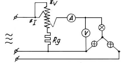 iP. 7 Electric circuit diagram in experience 2.
According to the instrument readings, it is established that the power of one phase is equal to the product of the phase voltage on the current in the phase.
Considering the total symmetry of the chain of the three-phase current shown in Figure 4, calculate the power of the entire chain, multiplying the testimony of the wattmeter by 3.
8.4.1 Multimeter installations
This section describes the details on the multimeter settings.
Measurement options
To select a measurement type:
1. Click one of the following buttons:
Ammeter.- Measures the current flowing through the chain in the branch between the two nodes. Turn on the multimeter sequentially with a circuit for measuring the flowing current, as well as a real ammeter (as shown in the diagram below).
To measure the current of another node in the chain, turn on another multimeter sequentially in this circuit and activate the diagram again. When an ammeter is used, the internal resistance is very low (1 ohms). To change resistance, click on Set.See "Internal Settings - Multimeter Settings dialog box.
Voltmeter.- Measurement of voltage between two nodes. Select V and connect the voltmeter terminals parallel to the load (as shown in the diagram below).
When used as a voltmeter, the multimeter has a high input resistance of 1 gom, which can be changed by clicking Set. See "Internal Settings - Multimeter Settings dialog box.
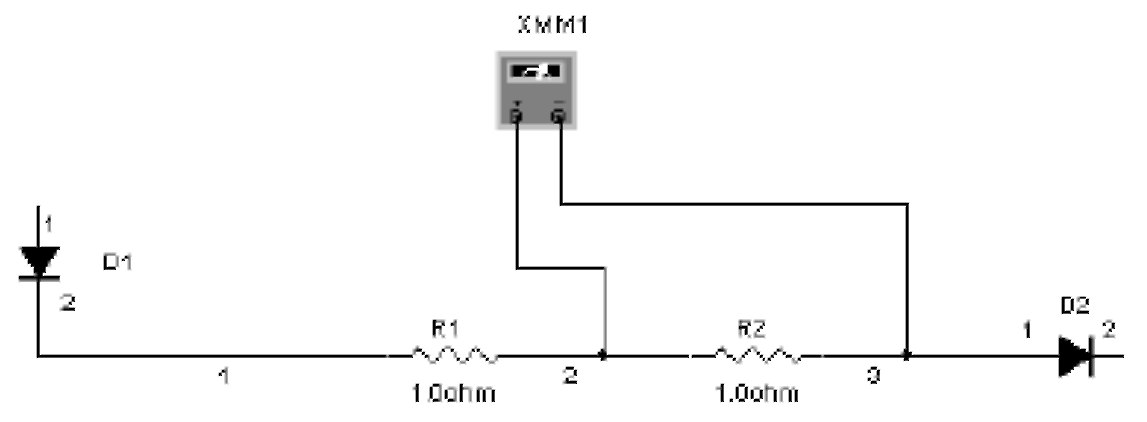
Ohmmeter.- This option for measuring resistance between two nodes. Nodes and everything that lies between them belongs to the "network of components". To measure the resistance, select this option and connect the multimeter terminals parallel to the network components (as shown in the diagram below).
To measure the measurement is accurate, make sure that:
No source in the network of components
Component or network component grounded
There is nothing in parallels with a component or network of components.
Ommeter generates a current of 10 to, which can be changed after clicking Set. See "Internal Settings - Multimeter Settings dialog box. If you change the connection of the Ommeter, activate the scheme again to read the result.
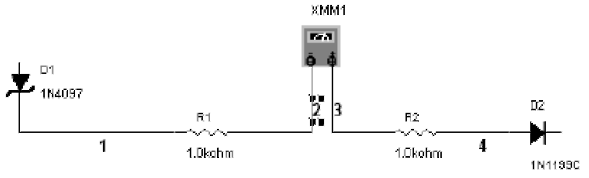
Decibels.- Measures the voltage drop in the decibels between the two nodes of the scheme. To measure in decibels, select this option and plug the multimeter terminals parallel to the load (as shown in the diagram below).
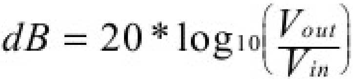
The standard for calculations in decibels is set to 774.597 mV, but it can be changed by clicking SET.. See "Internal Settings - Multimeter Settings dialog box. Losses in decibels are calculated as follows:
Operating Mode (AC or DC)
A button with a sinusoid for measuring the range (RMS) voltages or currents of alternating voltage. The signal of any DC component will be eliminated, so that only the AC component signal will be measured.
Measurement button direct current and voltage for DC signal.
Note: To measure the RMS voltage of the circuit and with AC, and with DC components, connect the AC voltmeter, like the voltmeter DC to the corresponding nodes and measure the AC and DC voltage.
The following formula can be used to calculate the RMS voltage when and AC, and DC components are in the diagram. This is not a universal formula, and should only be used in conjunction with Multisim.
Internal Settings - Multimeter Settings dialog box
Ideal devices do not make changes to the measured chains. The perfect voltmeter must have endless resistance, so that the current through it should not flow when it is connected to the chain. The perfect ammeter should not make resistance to the chain. Real devices do not correspond to this ideal, so their testimony will be very close to theoretical, calculated values \u200b\u200bfor the schema, but will never be absolutely accurate.
Multimeter in Multisim uses very small and very large numbers, which are approaching zero and infinity to calculate imperfect values \u200b\u200bin the diagram. For special occasions, however, the behavior of the meter can be changed by the ignition of these values \u200b\u200bto simulate the effect on the scheme (values \u200b\u200bshould be higher than 0).
For example, if the voltage in the diagram with very large resistance is measured, increase the voltmeter resistance. If the measured current in the chain with a very small resistance, reduce the resistance of the ammeter even more.
Note: A very small ammeter resistance in a high-resistance chain can cause a mathematical rounding error.
To display internal default settings:
1. Click Set. A dialog box appears Multimeter Settings.
2. Change the desired options.
3. To save your changes, click on OK.To cancel, click on Cancel.
8.5 Functional generator
A functional generator is a source of voltage of sinusoidal, triangular and rectangular shape. This gives a convenient and realistic way to submit stimulating signals into the scheme. The signal form may vary, and its frequency, amplitude, diet and constant component (DC Offset) can be controlled. The frequency range of the functional generator is quite large for feeding convenient AC and audio, and radio frequency signals.
The functional generator has three outputs to connect to the diagram. The total output has a reference signal for the signal.
Function Generator.on the panel Instrumentsand click to accommodate the icon in the workspace. The icon is used to connect the functional generator with the scheme. Double-click the icon to open the panel, which is used to enter the settings and view the measurement results.
For the correlation of the signal from the ground, connect the total output to the land of the component. A positive output (+) gives a positive signal relative to the neutral overall output. Negative (-) output, negative signal.
Note: If you are not familiar with the connection and configuration of the tool, see "Adding tools to the scheme" and "Using Tools".
8.5.1 Functional Generator Settings
Select alarm form
You can choose one of the three different types of signal shape as an output.
To select the waveform, click on Sine-, Triangular- or Square-Wave. Button.
To set the time settings / decline in the rectangular signal:
1. Click on the button Square-Wave.Button Set Rise / FallTime becomes active.
2. Click the button SET RISE / FALL TIME To display the dialog box SET RISE / FALL TIME.
3. Enter the desired time RISE / Fall Time and click by Accept.
Signal options
Frequency (1Hz - 999 MHz)- the number of cycles per second generated by the signal.
Duty Cycle (1% - 99%)- Accuracy of the active state to passive (on-period to off-period) for the triangular and rectangular waveform. The option is not applicable to
sinusoidal signal.Amplitude (1mv - 999 KV)- controls the signal voltage measured from its level DC to peak. If the supply wire is connected to a common and positive or negative output of the instrument, measurement from the peak to the peak of the signal is a double amplitude. If the output comes from positive and negative conclusions, the measurement from peak to peak is a quantity amplitude.
Offset (-999 KV and 999 KV)- controls the DC level, relative to which the variable signal changes. Offset in position 0, the signal passes along the x oscilloscope axis (provided that Y POS is set to 0). A positive value raises the level of DC upwards, while the negative value lowers down. Offset uses units set for Amplitude.
8.6 wattmeter
Wattmeter measures power. It is used to measure the values \u200b\u200bof the active power produced by the voltage drop and the current flowing through the conclusions in the diagram. The result is displayed in watts. The wattmeter also shows the power coefficient calculated by the shift between the voltage and the current and their work. Power factor is a cosine of the phase angle between the voltage and the current.
To use the tool, click on the button. Wattmeter. On the panel Instrumentsand click to place the icon in the workspace. Icon is used to connect Wattmeter. with a scheme. Double-click on the icon to open the instrument panel, which is used to enter the settings and view the results.
8.6.1 Wattmeter Connection
An example of a wattmeter connection is shown below. Detailed tool connection, including the wattmeter, is described in the "Adding tools to the diagram".
Note: If you are not familiar with the connection and configuration of the tool, see "Adding tools to the diagram" and "Using Tools" before using these tools.
8.7 oscilloscope
To use the tool, click on the button. Oscilloscope.on the panel Instrumentsand click on the place where the icon should be placed. The icon is used to connect the oscilloscope to the diagram. Double-click the icon to open the instrument panel that is used to enter the settings and view the measurement results.
The two-channel oscilloscope displays the value and change of the frequency of the electrical signal. It shows a schedule of one or two signals at the same time, or allows you to compare signals.
Note: If you selected saving results in files.lvm or.tdm, a dialog will appear Data Resampling Settings.See "Saving Files". In addition to saving the button Save.oscilloscope, you can save results
Simulations in the window Grapher.See "Saving Files".Note: If you are not familiar with the connection and configuration of the tools, see "Adding tools to the diagram" and "Using Tools".
8.7.1 Installation of oscilloscope
Temporary base
Setting the time base controls the scale of the oscilloscope horizontally or X axis when the signal and time value (Y / T) is compared.
To get a well-readable display, configure the timeline in return to the frequency settings of the functional generator or the source of alternating voltage - the higher the frequency, the smaller (less value) the temporary base.
For example, if you want to see one cycle of 1 kHz signal, the temporary base must be about 1 milliseconds.
Position by X.
This setting controls the starting point of the signal to the X axis. When position 0, the signal starts from the left edge of the display. A positive value (for example, 2.00) shifts the starting point to the right. A negative value (for example, -3.00) shifts the starting point to the left.
Axis (Y / T, A / B and B / A)
The axis of the oscilloscope display can switch between the ratio of the ratio value / time (Y / T) and the display of the channel ratio (A / B and B / A). Recent installations display the frequency ratio and phases known as Figures Lissuzh, or they can show the hysteresis loop. When the channel A and B (A / B) is compared, the scale of the x axis is determined by the volt / division for the channel B (and vice versa).
Ground
There is no need to ground the oscilloscope if the diagram to which it is connected, grounded.
Installations Channel A and Channel B
Scale
This setting determines the scale along the Y axis. It also controls the scale along the X axis if A / B or B / A is selected.
To get a readable display, set the scale according to the expected voltage in the channel. For example, the input AC signal in 3 volts fills the oscilloscope display vertically when the Y axis is set to 1 V / DIV (1 volt / division). If the scale is zooming, the signal form will decrease. If the scale is reduced, top part The signal will be beyond the display.
Position on y.
These settings are controlled by the starting point along the Y axis. When the position Y is set to 0.00, the initial point crosses the X axis. Increasing the position Y to 1.00, for example, will shift 0 (starting point) up to the first division over the X axis. will shift it down to the first division below the X axis.
Changing the N position setting for channels A and C can help see the signals for comparison.
Connecting inputs (AC, 0 and DC)
When the AC is selected, only the variable component of the signal is displayed. The AC connection is similar to the addition of the condenser sequentially with the input of the oscilloscope. As in the real oscilloscope when using the AC connection, the first cycle is displayed not exactly. When the constant component of the signal is calculated and removed at the first cycle, the signal shape becomes accurate. When connected DC, the sum of the variable and the constant component of the signal is displayed. Select 0 Displays a straight line at the source point of the position of the position Y.
Note: Do not place the condenser sequentially with an oscilloscope input. Through the oscilloscope will not pass current, and the tests will consider the capacitor as incorrectly included. Instead, select AC Connect.
Trigger
These settings determine the conditions in which the signal is initially displayed on the oscilloscope display.
TRIGGER EDGE (external signal front)
To start displaying a signal in its positive direction or a rigging signal, click the button "Ascending EDGE".
To start displaying a signal in its negative direction or the dropping signal, click the button "Descending EDGE".
TRIGGER LEVEL (switch level)
Switching level is a point on the y axis of the oscilloscope, which should cross with the signal level before displaying it on the display.
Trigger Signal (Switching Signal)
The switching signal may be internal, with reference to the input signal of the channel A or B, or external, with reference to the signal at the output of external synchronization. If this "flat" signal, or if the signal should be displayed as early as possible, select AUTO.
Use the button Sing., To ensure the oscilloscope trigger, the only pass to the meeting with the switching point. When the curve reaches the end of the oscilloscope screen, the curve will not change until you do not click on the button Sing.
Use the button Nor.So that the oscilloscope updates each time the image when the switch is reached.
Use the button NoneIf you do not need to use switching.
| Forward |
|---|


