The task of hydraulic calculation of the inner water supply is to ensure the normal operation of all watershed instruments located in the designed building. The consumption of water flowing from waterborne reinforcement with a fully open crane depends on its hydraulic resistance and the type, from the pressure of the pressure in front of the reinforcement. Each type of waterborne reinforcement has its own regulatory consumption (Appendix 4). This regulatory consumption is provided with a certain free regulatory pressure in front of the reinforcement. The value of the active free pressure, m, before the watersum reinforcement is determined by the difference between the warranty pressure in the city network, M, and the sum of the pressure loss when water moves to a given water treatment point, m, composed with the geometric height of the lift, m
In other words, the free pressure is what remains of the warranty pressure after all the pressure losses and water lifting to a certain height when it is moved to a given water treatment point.
It is obvious that in the most disadvantageous position there will be the most remote and highly located from entering the water treatment point, to which the amount of losses will be the greatest. Such a waterproof point is called dictational. It contains the calculation.
Power loss on each section of the inner water supply depend on the flow of water flowing through the portion, the length of the section and the diameter of the pipes. The main purpose of the hydraulic calculation of the water supply network is the selection of the most economical diameters of pipelines and the determination of the desired pressure to skip the estimated water expenditures.
The calculation is performed in the following order.
The selected estimated direction of the water movement (from input to the dictational point) is divided into calculated areas. For the settlement area, a part of the network with a constant flow rate and a diameter between the two watershed points is taken. Each settlement section of the water supply network is denoted by numbers 1-2, 2-3, 3-4, etc., the numbering lead from the tight hole of the dictating crane from top to bottom to the water unit.
After determining water spending on all calculated areas, pipe diameters are prescribed. To select pipe diameters, use tables of hydraulic calculation of pipes. In these tables, the permissible water flow rate, m / s, is given for various diameters and expenses.
The diameters of the pipes of internal water supply networks should be prescribed from the calculation of the largest use of the warranty pressure of water in the outer water supply network.
The speed of water in the pipelines of internal water supply networks should not exceed 3 m / s. The optimal speed of water movement is the speed of 1.5 ... 2 m / s. The most economical velocities are within 0.9 ... 1.2 m / s. These speeds should serve as a reference when appointing pipe diameters. In this case, the diameter of the pipes of intra-quarter networks of the water supply is taken 15 mm.
In the same tables, depending on the consumption of water and the diameter of the pipeline, the values \u200b\u200bof hydraulic sludges (pressure loss per unit of pipeline length) are shown on the basis of which hydraulic pressure losses are determined by the length of each calculated area by the formula
where is the length of the calculated area, m.
The entire calculation of the inner water supply is reduced to the table. 1.2.
Table 1.2.
Hydraulic calculation of the water supply network
Next, determine the pressure of the pressure required to supply the regulatory consumption of water to the dictational water treatment device with the greatest economic and drinking water consumption, taking into account the loss of pressure on overcoming resistance along the way of water movement.
where is the geometric height of water supply from the point of attachment to the external network to the dictational water treatment device, m;
- pressure loss in the introduction, m;
- pressure loss in the water meter, m;
- the sum of the pressure loss in length of the settlement sites, m;
1.3 - the coefficient that takes into account the pressure losses in local resistances, which for the networks of household and drinking water pipes of residential and public buildings are taken in the amount of 30% of the pressure loss in length;
- Working normative pressure at the dictational water treatment device, M acceptable by Appendix 4.
, (1.15) \u003d 3 m / s. In this case, the disposable warranty pressure will be most fully used.
If the need for pressure is a bit more warranty, you should try in some areas to increase the diameter of the pipeline in order to reduce the loss of the pressure. Such an operation can be recommended if the missing pressure does not exceed 50% of the amount of pressure loss in length.
With a significant shortage of pressure, it is necessary to calculate the rising pumping unit.
Send your good work in the knowledge base is simple. Use the form below
Students, graduate students, young scientists who use the knowledge base in their studies and work will be very grateful to you.
Posted by http://www.allbest.ru/
Ministry of Emergency Situations of Russia St. Petersburg University of State Fire Service
Department of Firefare, Emergency Rescue and Automotive Economy
Course project
in the course "Firewater Water Supply"
Topic: Hydraulic Calculation of the Outdoor United States Polywood
St. Petersburg - 2012
It is required to determine economic and drinking and industrial water consumption in the water supply system serving the settlement (village) and the enterprise.
Initial data:
The number of residents in the settlement - 35,000 people .
Buildings are equipped with internal water supply, sewage and bathrooms with local water heaters.
Building building in 3 floors.
In the village there is a laundry on a mechanized 700 kg of dry linen, less than 10,000 m3. Bani building 3-storey.
The main water supply network and waterways are laid from steel pipes with internal plastic coating. The length of the hydrodams from the NS-II to the water tower Lodvod \u003d 600 m.
Industrial enterprise for fire danger refers to category IN, Two production corps I degree of fire resistance: one volume of 400 thousand m3, another 570 thousand m3, the width of the building is 74 m.
The area of \u200b\u200bthe enterprise is 178 hectares. The company operates in three shifts, the number of workers in each change NCM \u003d 500 people. Water consumption for industrial needs. The shower is taken by 60% of workers in shift.
The general plan of the water supply network is shown in Fig. 1.1.
Fig.1 - Scheme of the combined economic - fire fighting pliving of the settlement and enterprise:
1 - Sanitary zone of artesian wells; 2 - Clean water tanks; 3 - switching chamber; 4 - pumping station; 5 - water fluids; 6 - water tower; 7 - plumbing network village; 8 - Enterprise.
1. Definition of water consolments
The combined economic and drinking, production and fireproof water supply should ensure the flow of water to the economic and drinking needs of the settlement, the economic and drinking needs of the enterprise, the household needs of public buildings, the production needs of the enterprise, the extinguishing of possible fires in the village and in the enterprise.
2. Calculation of the required expenses Water for the village and enterprises
Determination Water consumption is starting with the village because it is the main consumer.
Village. In accordance with paragraph 2, Table 1 of the water consumption rate per person accept 200 l / day.
Daily consumption:
Daily consumption taking into account Notes 4, p.2.1
Estimated water consumption per day the largest water consumption
According to paragraph 2.2, we accept ksut.mima \u003d 1.2
Estimated clock Maximum water consumption:
Maximum clock unevenness coefficient
We accept according to claim 2.2. and Table 2 MAX \u003d 1.3, MAX \u003d 1.175,
Then KCh.Mima = 1.3 * 1.175 = 1.5275
According to these instructions, we accept KCh.Mima \u003d 1.5
Water consumption for economic drinking needs of the hotel
where: Qkot \u003d 75 l / day
Coefficient of clock unevenness of water consumption for hospital
Total water consumption in the village:
Company
In accordance with clause 2.4, and according to the task, the rate of water consumption for economic and drinking needs for one person is accepted in shift
Water consumption in shift:
Daily water consumption:
Water consumption for showers in shift
Number of shower nets:
Water consumption for production needs in shift:
(on task), per hour
Daily water consumption for industrial needs:
Thus, the estimated daily flow consumption of the enterprise will be:
The total consumption of water per day in the village and enterprise is equal to:
We make a table of total water consumption by hours of the day (Table 1)
Explanation to the table. 2.1:
In column 1, there are clock gaps from 0 to 24 hours;
In column 2 - water consumption by the village by the hour of the day in% of daily water consumption at QC \u003d 1.45.;
In column 3 - water consumption village for economic and drinking needs for every hour in m3
In column 4 - the water consumption for the economic and drinking needs of the public building on the hour of day in% of the daily flow. The distribution of costs for the hour of day is customary by Appendix at QC \u003d 2.5;
In column 5 - the number of water in M3, spent by the hospital for economic and drinking needs for every hour of day
In column 6 - consumption for economic and drinking needs of the enterprise by the hour of shift in% of the changeable consumption. The distribution of costs by the hour of shift is made at QC \u003d 3.
In tab. 1 Danor the distribution of expenses for economic and drinking needs of the enterprise for 3 replacement work.
Table 1 - Water consumption for the hour of day in the village and at an industrial enterprise.
|
Company |
Total per day |
||||||||||
|
Economical - drinking needs |
Public building |
Economy - drinking water consumption |
% of daily |
||||||||
|
(factory-kitchen) |
water consumption |
||||||||||
|
% from qt. Max |
% of quantity here |
% from QPRSM. C-HP |
|||||||||
In column 7 - the number of water in M3, spent by the enterprise for economic and drinking needs for every hour of shift
In column 8 - water consumption for the work of the soul, which is taken into account within an hour after the work of each shift
In column 9 - water consumption for industrial needs, uniformly distributed by the change
In column 10 - the sum of the cost of all consumers at a certain hour of the day in m3
In column 11 - the sum of the costs of all consumers at a certain hour in percent of the total daily flow rate
When drawing up the table, it is necessary to control the summation of the columns, for example, the sum of the graph 3 must be equal, etc.
From table. 2.1 It can be seen that in the village and at the enterprise the greatest water consumption occurs from 8 to 9 hours, at this time, 897.75 m3 / h or
On the enterprise, the estimated consumption:
Calculated consumption of public building (factory-kitchen):
Actually, the village spends:
According to the column 11 tab. 1 Build a schedule for the uneven water consumption of the combined water pipeline by the hour.
3. Determination of the calculated water expenditures for fire extinguishing
We define the calculated expenditures of water for fire extinguishing according to the given example. Since the plumbing in the village is projected by the combined, then according to SNiP 2.04.02-84, paragraph 2.23 with the number of residents of 35,000 people. We accept 2 simultaneous fires. According to clause 2.12, Table. 5 With a 3-storey building with a water consumption of 25 l / s per fire.
Water consumption on the inner fire extinguishing in the village in the presence of a hospital, the building is a three-story volume of 10,000 m3, according to SNiP 2.04. 01 - 85, p. 6.1, Table. 1 We accept one jet, with a capacity of 2.5 l / s
According to SNiP 2.04. 02-84, paragraph 2.22 at the enterprise we accept 2 simultaneous fires, because The area of \u200b\u200bthe enterprise is more than 150 hectares.
According to paragraph 2.14, Table 8, Note 1, the estimated water consumption for the building of 570 thousand m3.
In this way, .
According to SNiP 2.04. 01-85, p.6.1, Table 2 Estimated water consumption for internal fire extinguishing in production buildings Enterprises are accepted at the rate of four jets with a capacity of 5 l / s each, then.
In this way,
Therefore, according to paragraph 2.23 SNiP 2.04.02-84, water consumption for fire extinguishing targets in the village and in the enterprise we define as the amount of water consumption in the enterprise and consumption in the village:
4. Hydrachlich extra calculation of the water supply network
Consider the hydraulic calculation on the example of the water supply network shown in Fig. 4.1. The total water consumption per hour of maximum water consumption is 215.42 l / s, including the concentrated consumption of public building 0.081 l / s.
Fig.2 - Drawing diagram of the water supply network
Determine evenly distributed consumption:
We define the specific water consumption:
We define travel selections:
The results are shown in Table. 2.
Table 2.
We define nodal expenses:
Similarly, we determine the cost of water for each node. The results are shown in Table 3.
Nodal expenses
Table 3.
Add concentrated costs to nodal expenditures. A concentrated consumption of the enterprise is added to the nodal consumption at point 5, and at point 3 - a concentrated consumption of a public building (instead of a point 3, you can take any other point). Then Q5 \u003d 34.47l / s, Q3 \u003d 28,725 l / s. The values \u200b\u200bof nodal expenses are shown in Fig. 4.2. Taking into account the concentrated expenses QUL \u003d 229.8L / s.
Fig.3 - Calculated Waterproof Scheme with Nodal Costs
Perform a preliminary distribution of water costs in the network sections. We will first take it for a plumbing network with maximum economic water consumption (without fire). Choose a dictating point, i.e. Point of meeting two streams (the end point of water supply). In this example, for the dictating point, we take a point 5. Pre-schedule the direction of water movement from point 1 to point 5 (directions are shown in Fig. 4.2). Water flows can go to point 5 in three directions: the first 1-2-3-4-5, the second 1-7-4-5, third 1-7-6-5. For node 1, the following condition should be performed: the amount of expenses in sections 1-2, 1-7 and nodal flow Q1 should be equal to the total water flow rate entering the network. That is, the ratio Q1 + Q1-2 + Q1-7 \u003d Q / VP. The values \u200b\u200bQ1 \u003d 22.98l / s and QPos.Pr \u003d 229.8l / s are known, and Q1-2 and Q1-7 are unknown. We ask arbitrarily one of these quantities. Take, for example, Q1-2 \u003d 103.4 l / s. Then Q1-7 \u003d QPos.Pr- (Q1 + Q1-2) \u003d 103.4 l / s. For point 7, the following ratio must be observed:
q.1-7 = q.7+ q.7-4+ q.7-6
The value Q1-7 \u003d 103.4 l / C and Q7 \u003d 40,215 l / c is known, and Q7-4 and Q7-6 are unknown. We are specified arbitrarily one of these quantities and accept, for example, Q7-4 \u003d 31.6 l / c. Then Q7-6 \u003d 31.6 l / s.
Water costs for other areas of the network can be determined from the following relations:
q4-5 \u003d Q7-4 + Q3-4-Q4,
As a result, it will turn out:
q2-3 \u003d 76,675 l / s,
q3-4 \u003d 45.95l / s,
q4-5 \u003d 26,345l / s,
q6-5 \u003d 8.62l / s,
We begin to pre-distribute water costs from the dictational point. Water expenses will be refined later in the implementation of the plumbing network. The plumbing circuit with pre-distributed costs in the usual time is shown in Fig.4.
Fig.4 - Calculation of the water supply network with pre-distributed costs with economic - industrial water consumption
In case of fire, the plumbing network should provide water supply for fire extinguishing at the maximum water consumption of water to drink and drinking and manufacturing needs with the exception of water costs per shower, irrigation of the territory, etc. industrial enterprise. (p.2.21 SNiP 2.04.02 - 84), if these costs entered into consumption per hour of maximum water consumption. For a water supply network shown in Fig. 4.1, Water consumption for fire extinguishing should be added to the node consumption at point 5, where water is selected on an industrial enterprise and which is the most remote from the input location (from point 1), i.e. q "5 \u003d Q5 + Q Royalty FreeCH .. water pipe tank pump.
With a hydraulic network calculation in the fire:
Because The nodal costs in the fire will be different than an hour of maximum water consumption without a fire. We define the nodal costs as it was done without a fire.
The calculated diagram of the water supply network with nodal and pre-distributed expenditure in the fire is shown in Fig.4.4.
Fig.5 - The design scheme of the water supply network with pre-distributed costs "in the event".
Determine the diameters of the pipes of the network participants. For steel pipe e \u003d 1.
According to the economic factor and pre-distributed water costs, the diameters of the pipes of the plotting of the water supply network are determined by the application.
The corresponding calculated internal diameters are determined according to GOST 539-80 and equal (WT-9 \u200b\u200bpipes, type I)
d1-2 \u003d 0.516 m; d2-3 \u003d 0.466 m; d3-4 \u003d 0.412 m;
d4-5 \u003d 0.466 m; D5-6 \u003d 0.311 m; D6-7 \u003d 0.311 m;
d4-7 \u003d 0.311 m; D1-7 \u003d 0.516 m;
It should be borne in mind that it is usually recommended to determine the diameters at pre-distributed costs without taking into account the water consumption for fire extinguishing, and then check the water supply network with the diameters found in this way on the possibility of passing water costs. At the same time, in accordance with paragraph 2.30, the maximum free pressure in the network of the combined water supply should not exceed 60 m. If in our example, determining the diameters according to pre-expenses at maximum economic water consumption (i.e., without taking into account the water consumption for fire extinguishing), then The following diameters are obtained:
d1-2 \u003d 0.363 m; d2-3 \u003d 0.311 m; D3-4 \u003d 0.26 m;
d1-7 \u003d 0.363 m; D7-4 \u003d 0.2 m; d7-6 \u003d 0.2 m;
d4-5 \u003d 0.17 m; D6-5 \u003d 0.114 m;
Calculations have shown that with these diameters of the pressure loss in the network with a fire of more than 60 m. This is explained by the fact that for relatively small settlements, the ratio of water expenditures on the plots of the water supply network during the fire and with maximum economic and production water consumption is quite large.
Therefore, the diameters of the pipes of some areas should increase and re-perform the hydraulic calculation of the network at maximum economic water consumption and in a fire.
In connection with the foregoing and to simplify the calculations in the course project, it is allowed to determine the diameters of the network sections in advance floods during the fire.
Linking a water supply network with maximum production water consumption.
When linking the loss of pressure in cast iron pipes should be determined by the formula:
Network links continues until the residual value in each ring will not be less than 1 m.
It should be borne in mind that for the site 4-7 (Fig. 4.3, 4.4), which is common to both rings, two corrections are introduced - from the first ring and from the second. The sign of correction flow when transferring from one ring to another should be saved.
Water streams from point 1 to point 5 (dictating point), as can be seen in the directions of arrows in Fig. 4.3, can go on three directions of arrows in Fig. 2.4, can go in three directions: the first - 1-2-3-4-5, the second - 1-7-4-5, third - 1-7-6-5. The average pressure loss in the network can be determined by the formula:
Power loss in the network with maximum production water consumption:
where: 1,1 is a coefficient that takes into account the loss of pressure in local resistances (10% of linear pressure losses are taken).
Conveniently engaged in the form of a table (Table 4.3).
Table 4. - Linkage of the network at maximum economic - industrial water consumption.
|
Ring number |
Plot network |
Water consumption |
Length L, m |
Speed \u200b\u200bV, m / s |
Hydraulic bias I * 10-3 |
||||
|
Power losses |
First correction |
||||||||
|
q "\u003d Q + DQ", l / s |
|||||||||
Table5 - Link the network with fire extinguishing costs.
|
Ring number |
Plot network |
Water consumption |
Settlement internal diameter DR, M |
Length L, m |
Speed \u200b\u200bV, m / s |
Hydraulic bias I * 10-3 |
|||
|
Power losses |
First correction |
||||||||
|
q "\u003d Q + DQ", l / s |
|||||||||
The calculated scheme of the water supply network with finally distributive expenditures with maximum economic and production water consumption is shown in Fig. 4.5.
Fig.6 - Calculation scheme of the water supply network with finally distribution costs at maximum economic water consumption.
5. Determining the mode of operation of the NS II.
We will take the two-stage mode of operation of the NS-II with water supply with each pump 2.5% per hour from daily water consumption. Then one pump per day will supply 2.5 * 24 \u003d 60% daily water consumption. The second pump must submit 100 - 60 \u003d 40% of the daily flow of water and it is necessary to include it by 40/25 \u003d 16 hours.
Fig.7 - NS mode -II. and water consumption schedule
In accordance with the water consumption schedule (Fig. 7), the second pump is proposed to include in 5 hours and turn off at 21 hours. This mode of operation of the NS-II is applied in Fig. 7 dotted line.
To determine the regulating capacity of the water tower tank, will be Table 6.
Table6 - Water consumption and pump mode of pumps.
|
Hour water consumption (see Table 1., Count 11) |
I option |
II option |
||||||||
|
Submitting pumps |
Admission to Buck |
Consumption from the tank |
Balance in the tank |
Admission to Buck |
Consumption from the tank |
Balance in the tank |
||||
In column 1, the hourly gaps are affixed, in column 2 - hour water consumption in% of daily water consumption in accordance with the graph 11 Table 2.1, in column 3 feeding pumps in accordance with the proposed operation of the NS-II.
If the supply of pumps is higher than the water consumption of the village, then the difference of these values \u200b\u200bis written in column 4 (admission to the tank), and if below - in column 5 (consumption from the tank).
The remainder of water in the tank (graph 6) by the end of a certain hourly gap is defined as the algebraic amount of the data Count 4 and 5 (positive when water intake into the tank and negative at the cost of it). For example, by the end of the first hour in the tank, 0.04% of the daily water consumption was accumulated, and to 4 hours 0.04 + 0.023 + 0.45 + 0.41 \u003d 1.13%. At four o'clock, water consumption in the village was higher than the supply of pumps and 1,13-0.45 \u003d 0.68% of the daily water consumption remained to the fifth hour in the tank.
The adjusting tank of the tank will be equal to the sum of absolute values \u200b\u200bof the greatest positive and lowest negative value of the graph 6. In the considered example, the tank tank capacity turned out to be equal
2.53 + -0.4 \u003d 2.93% of the daily water flow.
When performing a course project, it is recommended to analyze several modes of operation of the NS-II. Thus, for the reduced water consumption schedule, we define the tank adjustable tank for the step mode of operation of the NS-II with feed, for example, 3% of the daily water flow by each pump. One pump for 24 hours will supply 3 * 24 \u003d 72% daily flow. The share of the second pump will have 100-72 \u003d 28% and it should work 28/3 \u003d 9.33h. The second pump is invited to include from 8 to 17 hours.20 min. This mode of operation of the NS-II is shown on the graph of the barccotted line. The adjusting tank of the tank (columns 7,8,9,10 Table 5.1) will be 5.17 + -1.11 \u003d 6.28%, i.e. In this mode, it is necessary to increase the tank capacity of the water tower and finally choose the operation mode of the NS-II in the first embodiment.
6. Hydraulic calculation of water pipes
The technique for determining the diameter of the pipes of water pipes is the same as the diameters of the pipes of the plumbing network, set out in section 4 p. 7.
On the task, the waterways are laid from asbestos-cement pipes and the length of the hydrodams from the NS-II to the water tower Lodvod \u003d 600m.
Given that in the example, the uneven operation of the NS-II operation is adopted with the maximum supply of pumps P \u003d 2.5 + 2.5 \u003d 5% per hour from the daily water consumption, water consumption that will go through the waterways will be equal to:
Since the waterways should be laid in at least two lines, the water consumption is equal to:
With the value of E \u003d 1, we determine the diameter of the water pipes:
droke \u003d 0.3m; DVN. \u003d 0.311m.
The water velocity in the waterway is determined ...
Similar documents
Definition of water consumers. Calculation of the required water expenditures for the village and for the enterprise, as well as for fire extinguishing. Linking a water supply network with maximum production water consumption and in a fire. Calculation of the reservoir of clean water.
course work, added 30.11.2014
Determination of water consumption, calculation of the required water consumption for economic and drinking, production and fire needs of the settlement and industrial enterprise. Determination of the height of the water tower. Calculation of clean water tanks, selection of pumps.
coursework, added 03/25/2013
General Plan of the Textile Combine. Determination of estimated water costs. Hydraulic calculation of the water supply network for water skipping (before the fire). Pass losses on sites. Calculation of spare and spare-regulating containers. Tank volume of water tower.
course work, added 01/17/2015
Calculation of a stupid part of the water supply network. Determining pipe diameters. Choosing a trunk direction. Calculation of daily costs. Preparation of the main network to hydraulic calculation. Determination of the diameters of the water supply. The height of the water tower.
course work, added 01.02.2015
Calculation of the 2nd rise plumbing station, determining the station reliability category. Calculation of the capacity of the water tower tank. Design station, selection and placement of equipment. Determination of technical and economic indicators of the station.
course work, added 13.02.2016
Brief characteristic of the settlement. Calculation of water consumption for economic and drinking, production needs and fire extinguishing. Hydraulic calculation of the water supply network. Calculation of pressure-regulating containers and a second lifting pump station.
course work, added 08.10.2010
Calculation of the maximum supply of the pumping station. Determination of the diameter and height of the tower tower, pressure losses in suction and pressure waterways, the pressure of the pumps in the case of maximum water consumption, suction height. Selection of drainage pump.
course work, added 06/22/2015
Hydraulic calculation and construction of a water supply network. Brief description of the water supply facility, determination of the calculated cost of water in the city. Choosing a water supply system and tracing of water pipes, selection of pumps; Test, flushing, disinfection.
course work, added 09/27/2011
Select the mode of operation of the pumping station. Determination of the volume and size of the water tower tank. Determination of the capacitance of non-pressure reservoirs of pure water. Selection of pumps, constructing the characteristics of parallel operation of pumps, pipelines. Electrical part.
course work, added 09/28/2015
Calculation of the performance of the second lifting pump station. Building stepped and integral water consumption graphs. Calculation of the regulatory capacity of the water tower with uniform operation of the station. Selection of equipment and pipe fittings.
Hydraulic Calculation of Outdoor Water Supply Systems
The main task of calculating the outer water supply network is to determine the cost-effective diameter of pipes and pressure loss in all areas, based on the most economical mode of operation of the entire water supply system and the minimum cost of construction of water supply networks.
If the amount of water is known to be submitted to individual consumers, it is possible to determine the amount of water that must pass by a particular area of \u200b\u200bthe water supply network. When you turn off one line of the ring network, the water supply for economic and drinking needs for the remaining lines is allowed to be reduced by 30-50% depending on the number of power supply points, and in the most unfavorable point - no more than 75% of the calculated consumption. The free pressure at this point should be at least 10 m, and the overall supply of water is allowed to reduce no more than 30%. When calculating the network for fire extinguishing, turning off the lines of ring networks is not taken into account.
The hydraulic calculation of the network of the combined water supply system is carried out into two modes:
- Maximum economic and production water consumption from the network
Q. \u003d Q x-p. + Q pr. . . (5.1)
- extinguishing the estimated number of fires with the maximum economic consumption of water;
Q. \u003d Q x-p. + Q pr. +. Q fair . . (5.2)
The concept of the economically of the highest diameter originated from consideration of the collaboration conditions of the water supply network and the pumping station. To find the diameters of the network sections, it is necessary to know the calculated costs in these areas.
With small diameters of pipeline loss pipelines in the network, there will be large, and therefore, the total computational pressure of the pumps will increase. Therefore, a large amount of electricity will be consumed for the operation of pumps every day. At large diameters of pipe loss pipelines decrease, but the cost of construction of water networks increases.
The diameter of the pipes is selected taking into account the most economical velocities of the water movement in them, in which construction and operating costs will be minimal.
The most economical water supply networks at the speed of water is 0.7-1.2 m / s for pipes with a diameter of 100-350 mm and 1.0 -1.5 m / s for pipes with a diameter of 400-1000 mm. When calculating the network on the passage of fire consumption of water, an increase in speed is allowed to 2.5 m / s.
For a network that is subject to calculation, its configuration is always known (set) its configuration, the length of the sections and the selection of water in the nodes.
Hydraulic calculation of a dead-end (branched) external water supply network
In the tuning nodes (branched) network, water selection is given and, therefore, expenses in all areas in the direction and the magnitude are determined by the only possible way. This is due to the fact that from the initial node to any node there is only one possible way. The calculation starts from the most remote node on the main (main) line moving against the flow of water (Figure 5.1). This node is called a dictational point - it is the point most distant from the feeder and located in the most disadvantage (pressure at this point the largest). By consistent addition of nodal (concentrated) costs, you can get travel expenses by plots. At the same time, the first law of Kirchoff, expressing the balance of spending in nodes (Å q I.\u003d 0). The costs coming to the node are conventionally considered positive, and the costs that go from the node, including the concentrated selection, are negative. After calculating the main line, the calculation of branches is proceeded.
1 - pumping station II lifting; 2 - Water Tower; 3 - outdoor network
Figure 5.1 - Pupapless network circuit
Knowing the calculated costs and economically appropriate speeds, we select diameters on the Shevelev table or by the formula:
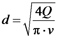 (5.3)
(5.3)
and determine the pressure loss for each site and the total losses on the network:
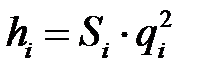 ; h C \u003d H 1 + H 2 + ... + H i, (5.4)
where S I. - pipe resistance;
q I. - Consumption on the site.
Then the calculation is then carried out in the same order, taking into account the expenditure on fire extinguishing. If the speed on any site exceeds the permissible 2.5 m / s, it is required to replace the pipes of the diameter of the pipes of the larger diameter, which reduces the speed of water. Then to calculate the pressure loss for the regime without taking into account the expenditure on fire extinguishing, taking into account the new diameters of pipes.


