Calculation of value
- Grounding the roof
Grounding the roof
Professional grounding of the roof - is it necessary?
Buildings of any height and destiny need protection against lightning strikes. Grounding the roof is the best solution to ensure the safety of the structure and its tenants. Regardless of the kind of roof material, any of unprotected buildings may be subject to the impact of the elements. Lightning protection is obligatory for public or industrial buildings, buildings whose height exceeds the height of other structures, structures that have powerful metal parts. For private houses, mandatory grounding of metal roofs, including copper and galvanized.
Why should I use the skills of professionals MZK-ELEKS?
We work in the sphere of grounding of the roof, starting in 2008. During this time, the system of supplying high-quality parts and equipment for creating professional lightning protection was established. Today there are many options for creating a reliable system of thunders and grounding, which our professionals know to the smallest detail. Of the important advantages of cooperation with us, it is worth highlighting the following:
- quality assurance for 2 years, including electrical resistance indicators;
- the presence of all certificates needed to carry out work, which serves as a guarantee of the quality and responsibility of our employees;
- reliable and time-tested by the best suppliers of materials and details;
- unlimitedness in difficulty or scale;
- departure to the object is paid by our company;
- always reasonable prices;
- providing several options for grounding the roof, the customer chooses the most appropriate option;
- our engineers take into account the pricing policy and wishes of the client;
- only our technique works at the facility, and only our brigades.
Main technical moments in the arrangement of a reliable grounding of the roof
To protect against lightning hits really worked, the grounding design should have a number of parts or nodes:
- grounded circuit or ground contour;
- connecting tire;
- lightning messages;
- additional automation to turn off the electrical power supply in the building.
All these elements have their own technical indicators and mandatory characteristics, with non-compliance with which the quality of protection is reduced and can lead to the fire.
To ground the roof work at the right time, experience, skills and availability of special equipment are needed.
In addition, before choosing some parameters of the grounding device nodes, it is necessary to carry out calculations, taking into account the characteristics of the soil, the terrain and the height of the building itself.
Also ne. last role Playing blood coat material. For metal structures, the lightning equipment can be the coating material itself. In such a case, a prerequisite is a quality electrical contact between metal sheets. If the thickness of the sheet steel used on the roof is less than 1 mm, then it is recommended to establish an additional cable system of lightning parameters. In accordance with RD 34.21.122-87, metal roofing, serving at the same time and lightning message, should have at least two contacts with the connecting bus. For proper and reliable operation of grounding of the roof, a number of requirements established by GOST and set out in the RD 34.21.122-87, paragraphs 2.11, 2.6, 2.7, 2.12, should be used, in some cases, it is possible to use a reinforced concrete foundation as a grounding circuit if the conditions of the item are performed. 2.2.
In industrial or public buildings where a powerful appearance is possible electronic magnetic field, Metal roofing and steel enclosures indoors are protected by grounding from static electricity. In this case, the norms defined in Pue chapter 1.7 are used.
Ground contour
Ground contour is a metal construction that is usually vertical metal rods immersed in the ground to the maximum depth. The minimum depth is 2.5 - 3 meters. The metal object must have the highest possible surface area to ensure the best contact with the soil and the minimum electrical resistance.
Steel corners are used as the grounding circuit parts (minimum size 50 × 50), steel fittings (section from 12mm) can also be used metal barrelmade of thick sheet metal (at least 3 - 4mm). The composition of the ground loop includes at least three iron cores or steel corners, which are connected to each other with a steel strip (cross section of at least 40 × 4mm), welded to each of them and forming a triangle shape. This design Must be fully immersed under the ground, to the depth of the soil. This is usually about 80cm. To improve the contact of the construction with soil, it is recommended to remove rainwater to the area where the contour is installed.
Connecting tires
The grounding circuit is connected to the parts of the lightning parametest with the tire. A steel strip of 40 × 4 mm can be used as a tire. It is welded to the connecting structure and is displayed on the electric shield through the trench. The depth of the grounding strip of at least 70 is 80 cm. Next, copper, steel galvanized, aluminum and stainless steel conductors can be used in the design and connection of the grounding system. The underlying condition is the compliance with the rules when choosing a conductor section. Since the strength of the current when lightning strikes can reach 10 - 300,000 A, the conductor must have a sufficient margin of strength in order to withstand the load, while not heated to limit and hazardous temperatures. The diameters of the sections of the conductors are selected by technical directories.
Lightning messages
Lightning message is a design that serves to receive and transmit the discharge of the lightning on the current tire or cable. The moline receiver can also serve as the roof itself if it is made of metal or copper. However, in such a situation, a prerequisite is a reliable contact between the sheets of the coating material, since at the final stage, the resistance of the ground design should not exceed 4 ohms.
The designs of lightning parameters and their technical parameters are determined in accordance with the RD 34.21.122-87, paragraph No. 3. The choice of lightning protection design is carried out in consent with the danger category assigned by the building. The determination of the lightning protection category is carried out in accordance with the RD 34.21.122-87, paragraph No. 5.
Additional automation
To protect against high current damage, a series is installed. circuit breakerswhich are configured to trigger when increasing the magnetic field of the grounding conductor. Such devices are characterized by increased response speed and require professional selection and configuration.
Further maintenance system maintenance
After installing and connecting a grounding structure, during operation it is necessary to perform regular measurement of the resistance value. Our company also offers service of bulky systems, including tracking the resistance of insulators and the ground.
For effective use Reinforced concrete and steel frames of buildings and structures as natural grounding devices, all elements of reinforced concrete and steel structures are required (foundations, columns, farms, rafter, tint beams, etc.) to combine each other so that they formed a continuous electrical circuit for metal And in reinforced concrete elements, in addition, mortgage parts should be provided for the addition of electrical and technological equipment.
In buildings with monolithic reinforced concrete frame continuity electrical chain It is ensured by direct welding of reinforcement rods of reinforced concrete products.
The continuous electrical circuit, the framework of the building made from the precast concrete elements, is created directly welding the mortgage products, adjacent to each other reinforced concrete elements either using steel jumpers with a cross section of at least 100 mm 2 (paragraph 1.7.78 Pue), which are welded to mortgage products connected reinforced concrete elements. Mortgage products must be welded to the reinforcement reinforced concrete elements with a length of at least 40 and a height of at least 5 mm (i.e. that the cross section of the weld was at least 100 mm 2).
In buildings with a metal frame for creating a continuous electrical circuit, welded joints can be used, but sufficient bolted and rivet connections that provide construction requirements for the joint work of the framework elements can be used. In those places where such compounds are absent, steel jumpers should be provided, each cross section of at least 100 mm 2, welded to the joint constructs, the total cross section of which should be at least 100 mm 2.
Fig. 1. Combining the frame with a lightning grid:
1 - metal mesh; 2 - steel jumper; 3 - Armature of the column; 4 - Foundation Armature, 5 - building construction
Design solutions that ensure the electrical continuity of the reinforced concrete or steel framework of an industrial building are given below.
For one-storey buildings with reinforced concrete frame, the following ways of combining the building frame are used.
1. Association with a lightning grid (Fig. 1). The lightning grid is made of steel rods or wire with a diameter of 8 mm with a pitch of 6 m for lightning protection buildings in category II and in 12 m in category III. The grid stacked on the plates to the roofing device under the insulation layer from non-combustible materials. Grid nodes in the intersection places are welded (Fig. 2). The lightning grid must be connected to the reinforcement of columns and foundations.
Technical solutions of nodes I - IV are given respectively in Fig. 3 - 7.
The main coordinate sizes of single-storey buildings are accepted according to GOST 23838 - 79 (Table 8).
Table 8. The main coordinate sizes of single-storey buildings
Building type |
Main coordinate sizes, mm |
||
1. Without bridge suspension and support cranes and equipped with bridge suspension cranes of general purpose |
6000 - 12,000, more than 12,000 |
3000 - 8400, more than 8400 |
|
2. Equipped with bridge handproof cranes |
9000, 12 000, more than 12,000 |
6000 - 9000, more than 9000 |
|
3. Equipped with bridge electric support cranes of general purpose |
|||
Note. LQ - modular steps of columns over the transverse coordinate axes or a modular span width; C - modular steps of columns along the longitudinal coordinate axes or modular steps of columns; Yao - modular floors heights. 
Fig. 2. The location of the lightning grid and connecting parts (A) and the compound of zipper grids located at different levels (b):
1 - metal mesh made of reinforcement rods with a diameter of 8 mm; 2 - installation sites of connecting parts; 3 - Armature rod with a diameter of 8 mm
2. Combining the framework of the building using crane rails (Fig. 7). Crane rails used in the grounding device are shown in the plan in Fig. 8 A, the design solution of the node V - in Fig. 8 b. The modular width of the span, as well as Z0 and Ya0 are installed according to GOST 23838 - 79 (Table 8). 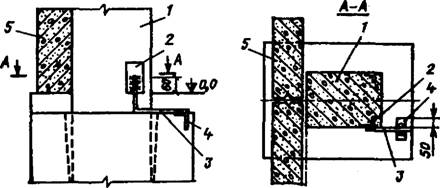
Fig. 3. Connection diagram of the mortgage product column and foundation:
1 - reinforced concrete column; 2 - the bottom mortgage of the column; 3 - connecting jumper with a diameter of 12 mm; 4 - Mortgage Foundation; five - wall panels
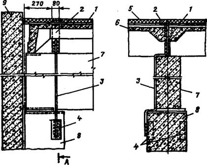
Fig. 4. Connection of a lightning grid with an upper folding column product:
1 - moths in advance mesh; 2 - connecting item; 3 - jumper with a diameter of 12 mm; 4 - upper mortgage product column; 5 - insulation; 6 - slabs of overlapping; 7 - construction construction; S - reinforced concrete column; 9 - Wall panels 
Fig. 5. Wall panel protection node:
1 - wall panels; 2 - rod with a diameter of 8 mm, welded to mortgage parts of wall panels and laid around the perimeter of the building;
- - jumper with a diameter of 8 mm;
- - lightning grid; 5 - overlap panel

Fig. 6. Node of the lightning grid over the location of the ceiling plates:
1 - lightning grid; 2 - overlapping panels 
Fig. 7. Combining the framework of the building with crane rails:
1 - Construction reinforced concrete structures; 2 - crane rails; 3 - crane beams; 4 - Armature of the column; 5 - Foundation fittings
3. Combining the framework of the building with the help of foundation beams (Fig. 9). The location of the foundation beams in the plan is shown in Fig. 10 d. All fundamental beams around the perimeter of the building must be connected with the fittings of the foundations, for example, as shown in Fig. 10, b.
In the locations of the openings, the conductor from strip or round steel is paved as shown in Fig. eleven.
The VI node is solved similarly to the receptions shown in the VII node. The modular width of the span is given in Table. eight. 
Fig. 8. Location of crane rails of buildings (A) and the connection of the crane rail with a mortgage product of the column (b):
1 - crane rails. 2 - crane; 3 - columns; 4 - subsensic beam; 5 - steel jumper with a diameter of 12 mm; 6 - Vertical Armature of the Column, 7 - Details of fastening of crane beams
4. Combining the framework of the building with steel farms (Fig. 9). In the absence of a lightning grid, crane beams, rails or foundation beams, but in the presence of metallic (steel) rafter and ending farms, these farms can be used to create a continuous electrical circuit. The design solution of the node I is shown in Fig. 3, node VII - in Fig. 13. The size L0 corresponds to the values \u200b\u200bshown in Table. eight.

Fig. 9. Combining the framework of the building with the help of foundation beams:
1 - lumpy design; 2 - Armature of the column; 3 - fittings of the rafter design; 4 - Foundation Beams
Fig. 10. The location of the foundation beams when using them to combine (a) and the connection of the values \u200b\u200bof the foundation beams between themselves and the reinforcement of the column (b):
1 - fittings for foundation beams; 2 - connecting rods with a diameter of 12 mm; 3 - foundation beams; 4 - foundation; 5 - mortgage product; B - Wall panels ![]()
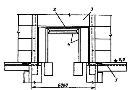
Fig. 11. Connection of the values \u200b\u200bof the foundation beams in the places of openings:
I - fittings for foundation beams, 2 - steel strip 3x40 mm or rod steel diameter
12 mm; 3 - wall panels; 4 - Rama Gate 
Fig. 12. Combining the framework of the building using steel farms: 1 - steel farm; 2 - Armature of the column; 3 - reinforced concrete column
For multi-storey buildings with reinforced concrete frame, the following ways of combining the frame of the building are used,
1. Association with riglels (Fig. 14). In industrial multi-storey buildings With a reinforced concrete frame, in the absence of a lightning protection grid, the reinforcement of the reinforced concrete frame is used by the reinforcement reinforcement (not having a pre-voltage) and extreme slabs of the overlap. The technical solution of the node VIII is shown in Fig. 15, node / - in Fig. 3. For greater clarity, the VIII node is shown in axonometry in Fig. 16. The main coordinate sizes of multi-storey buildings are shown in Table. eight.
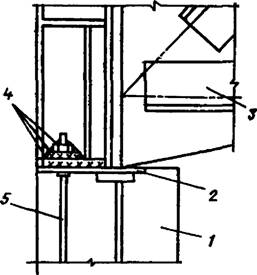
Fig. 13. Example of fastening the steel farm to the reinforced concrete column:
I - reinforced concrete column; 2 - a mortgage product; 3 - steel farm, 4 - attachment assembly; 5 - Anchor
Bolts.
Fig. 14. Association with riglels:
1 - Rigel Armature, 2 - Mounted Product For Earth Connection 

Fig. 15. Association of the framework of the building with the help of balls and slabs of overlapping:
1 - rectangular reiguel; 2 - mortgage products; 3 - extreme slabs of overlapping; 4 - column

Fig. 17. Association with a lightning grid; 1 - lightning grid; 2 - mortgage 
Fig. 16. Connection of the armature of the extreme plates of overlap with the reinforcement columns
1.2 - Plate reinforcement nodes with mortgage columns

Fig. 18. Options for connecting a lightning grid with reinforcement column:
1 - lightning grid; 2 - Connecting detail: 3 - overlap plates;
4 - Rigel; 5 - column
20. Association with a lightning grid (Fig. 17). The node of the compounds of the IX zipper grid with the reinforcement of the columns is shown in Fig. eighteen. 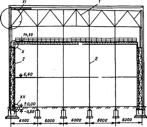
Fig. 19. Multi-storey building with metal frame:
1 - farm; 2 - Auxiliary column, 3 - Main column 
Fig. 20. Basic nodes (assembly) steel frame:
I - Overigital Stand; 2 - steel column of a permanent section; 3 - Poded Balk
For multi-storey buildings with a metal frame, electrical continuity is provided with the help of building structures (Fig. 19). The figure shows the face wall of the steel frame. The main mounting nodes of the steel frame X - XII are shown according to fig. 20 - 22. As can be seen from the drawings, the nodes are attached or welding, or on a thread bolts at least M20. The experiment showed that these compounds ensure the continuity of the electrical circuit without additional mounting work.
The continuity of the electrical circuit inside the reinforced concrete elements is provided by the welding of separate reinforcement rods of the frame and the mortgage products of the reinforced concrete elements with the frame of the framework.
Examples of the location of additional mortgage products and the methods of their compounds in the columns of one-storey buildings (the columns of the KE-01-52 series, 1.423-3, 1.423-5) are shown in Table. 9, and in columns of multi-storey buildings (1420 series columns) - in Table. 10. Mortgage products for technological or plumbing communications, metal platforms must be connected to the vertical reinforcement of the column, which is the ground mainstyle. Constructive execution reinforced concrete foundationsused as earthing.
Additional mortgage products shown in columns on intermediate marks, in a specific project are accepted on the task of electricity.
Knots II and III provide for the connection of reiguel reinforcement with the reinforcement of columns. These nodes are performed only in those columns that are used to combine reinforced concrete structures.
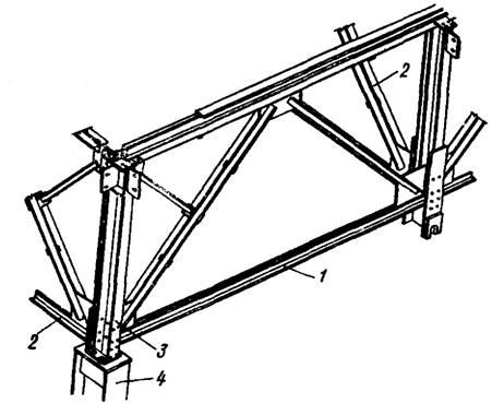
Fig. 21. Promotions of the adjuncing of rafter and subcording steel farms to the support rack and installing the column headband:
1 - a substropyl farm; 2 - a rafter farm; 3 - Outdoor rack; 4 - Steel Column

Fig. 22. Reinforced concrete foundation for steel column:
1 - steel column; 2 - reinforced concrete foundation; 3 - Foundation Bolts
Examples of the use of buildings designs as a grounding device. When using grounding properties of buildings, it is necessary to observe the following general requirements:
Connection of reinforced concrete column reinforcement columns with the foundation valves used as a grounding. Must be carried out with a jumper with a diameter of at least 12 mm. The compound of metal columns with reinforced concrete fittings reinforced concrete foundations is performed in fig. 22;
welding of mortgage products to working valves columns, reinforced carcass Popponnik foundation, as well as welding of all connecting elements, jumpers should be carried out by manual arc electric welding in accordance with the requirements of CH 393-78.
Table 9. The main coordinate sizes of multi-storey buildings with reinforced concrete frame (GOST 24336 - 80)
Building type |
Main coordinate size, mm |
||
1. With constant coordinate size (span width and column pitch) in all floors, with calculated loads on beams (rigge) overlap to 265 k11 / m |
6000, 12 000, more than 12,000 |
3300, 3600, above 3600 |
|
2. With an increased width of the span in the upper floor (with respect to the underlying), equipped with suspended electrical single-facing taps of general purpose with a carrying capacity from 0.25 to 5 tons, with calculated loads on the beams (riglels) of overlaps from 110 to 265 kN / m |
6000*, 9000*, 12 000* |
4800, more than 4800 |
|
3. With an increased span width in the upper floor (relative to the underlying), equipped with bridge electric cranes with a lifting capacity from 5 to 10 tons, with calculated loads on beams (riglels) of overlaps from 110 to 265 kN / m |
6000* |
4800, more than 4800 |
|
* For the first and middle floors.
** For the upper floor.
Note. Designation LQ - the width of the span or the modular step of the column along the transverse coordinate axes in multi-storey buildings with a reinforced concrete frame; In - a modular step of the column along the longitudinal coordinate axes or the pitch of the column; But - the modular height of the floor.
It is not allowed to use the following types of structures as elements of ground: reinforced concrete structures with stranded wire and spinning (cable) reinforcement; reinforced concrete structures with strained rod reinforcement with a diameter of less than 12 mm; Reinforced concrete foundations S. protective coatings surfaces used in medium and strongly aggressive environments; reinforced concrete foundations when they are located in the sands and rock soils with a humidity of less than 3%; reinforced concrete foundations from concrete B8 brand on waterproof and higher; Reinforced concrete structures of electrical installations operating on constant current.
It is allowed to use foundations as earthing in an aggressive medium at a chlorine ion concentration of up to 0.5 g / l (C1) or sulfations up to 10 g / l (SO4) in the event that the density of currents that flow from the foundations for a long time complies with the requirements, The "Guidelines for the use of grounding and reducing properties of building structures of industrial buildings and structures" developed by VNIIPEM, NIIZB and Goschimproduge.
If the foundations for columns cannot be used as earthing, a device of an external ground loop is needed to connect to it of currents from the assembly of the column of at least two places. The location of the connection points is determined by the task of the electrotechnical department.
All open parts of the currents must be galvanized or protected from corrosion by any other methods corresponding to the air aggressiveness. If building construction structures are used only for lightning protection, then:
The lightning protection device of the building using building structures includes a lightning-free mesh (or rod lightning lines), connected by metal jumpers with reinforcement of columns (or metal columns) and reinforced concrete foundates;
The reinforced concrete armature of reinforced concrete structures, used as a current, should also be continuous and ensure the transfer of electricity to the foundation-earthinger;
The lightning grid applied in the lightning protection system is laid on the coating plates to the roofing device under the layer of the insulation from non-combustible materials. To connect to the reinforcement of columns used as a current, the lightning grid is welded to special connecting products laid down in the seams between the coating plates. The junction step is set by electric.
In buildings with coatings on metal farms or beams, a lightning grid on the roof does not fit. In this case bearing structures Coatings should be linked to recesses from the rods of the steel of the steel A1 with a diameter of 12 mm. All metal parts located on the roof (pipes, ventilation devices, drain funnels, etc.) are connected to a lightning grid mesh or lightning conduction. On non-metallic towering parts of buildings, it is necessary to additionally put the metal grid and combine it with a welding with a lightning grid on the roof.
Rod lightning lines, installed on the roof of single-storey buildings, must be connected to the columns used as a current (see nodes of clause 2 Table 12).
In the case of the use of rod lightning systems in multi-storey buildings to mortgage products of the headlocks of the upper floor columns, it is necessary to weld anchor bolts for fastening lightning lines.
If building construction structures are used for protective grounding, then:
As elements of grounding devices, assembly of columns (or metal columns), riglels, slabs of overlapping, foundations, as well as metal designs of production purposes (railway tracks, platform beams, etc.) are used.
The continuity of the electrical circuit is provided by welding the metal jumpers with a cross section of at least 100 mm 2 in places of conjugates of the structural elements of the frame.
To connect the protective grounding of the equipment in columns, mortgage products are provided in accordance with the task of the electrotechnical department.
The symbols used in the projects are given in Table. 13.
Table 13. Legend
Designation
Conductor name
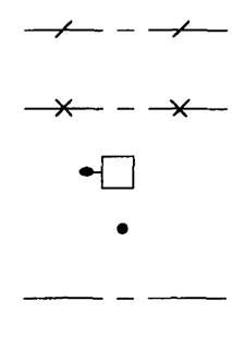
I. Migiston grounding of strip steel with a cross section of 40 x 4 mm
2. Natural grounding highways
3. Column with a mortgage part connected to the reinforcement of columns and foundation
4. Rod lightningwriter on the roof of the building
5. Steel with a diameter of 8 mm on the roof of a building laid under a layer of waterproofing
If it is impossible to provide the required resistance to natural grounding devices, it is necessary to provide for the construction of artificial. Artificial entrancers, as a rule, are performed from steel. Grounding devices should not be painted, except for the places of welded compounds of horizontal and vertical earthing, as well as horizontal earthing machines. These locations are painted with bitumen or other similar paints.
Horizontal earthing motors of electrical installations above 1 kV with effectively grounded neutral Must be tested for thermal resistance and corrosion destruction.
In case of risk of increased corrosion for earthingers, it is recommended to use steel only a round profile and an increased cross section. If the minimum allowable view is determined not thermal resistance, but only mechanical strength, then the cross-section of the grounding agents, depending on the aggressiveness of the soil is taken in Table. 1. With increased corrosion, galvanized or deposited earthing can also be applied.
The activity of the soil with respect to steel, depending on one of the parameters - the resistivity of the soil, affecting the rate of metal corrosion in the ground, is shown below.
| Corrosion activity of soils | Resistivity soil, ohm * m |
Very high |
|
Increased |
|
General requirements for constructive performing grounding devices are set forth in Table. 2.
Table 1. Earth section depending on the aggressiveness of the soils
Type of grounding device |
Corrosion activity of soil in relation to steel |
Mechanical admissible |
|
With steel vertical grounding |
Very high |
Steel Round diameter 16 mm * |
|
Increased, medium low |
For soft soils Steel Round diameter 12 mm |
Steel angular 63 x 63 x 6 mm |
|
Steel horizontal entrancers |
Very high, high |
Steel Round diameter 16 mm |
Steel strip 20 x 10, 30 x x 10, 40 x 10 mm |
Increased, middle |
Steel Round diameter 12 mm |
Steel strip 20 x 6, 30 x x 6, 40 x 6 mm |
|
Steel Round with a diameter of 10 mm |
Steel strip 20 x 4, 30 |
* Eggs of other forms are invalid by corrosion conditions.
Note. With an equal cross section, it is advisable to apply steel strips of greater thickness, but less width.
A grounding device that is performed in compliance with the requirements for tensioning the tension should provide at any time of the year when flowing off the closure current to the land of the tension voltage, not exceeding normalized. The impedance of the grounding device is determined by the permissible voltage on the grounding device and the circuit current to the ground.
When determining the value of the permissible tension voltage as the calculated exposure time, the sum of the protection time of protection and the full time of turning off the switch should be taken. When determining the permissible values \u200b\u200bof the touches of touch in jobs, where during the production of operational switchings there may be short-circuits on the designs available to touch the switching personnel, it is necessary to take the time of the reserve protection, and for the rest of the territory - the main protection.
Table 2. Requirements for constructive implementation of the grounding device
| The principle of normalization of the grounding device | Requirements for constructive implementation |
Compliance with the requirements for resistance or voltage |
1. Ground conductors connecting equipment |
Compliance with demand |
1. Longitudinal horizontal entries (conductors) |
Compliance with the requirements for tension |
Table 3. Conditions for equalizing the potentials around the industrial electrical installation or around the building in which it is posted
1. It is allowed to use reinforced concrete foundations of industrial buildings and structures as earthing in accordance with Pue, if the permissible level of potential leveling is ensured. Ensuring the conditions for equalizing the potentials using reinforced concrete foundations used as earthing, is determined based on the requirements given in this table. |
1. If the grounding device of an industrial or other electrical installation is connected to the ground of electrical installations above 1 kV with effectively grounded neutral cable with a metal sheath or armor or using other metal connections, then to level the potentials around such an electrical installation or around the building in which it is posted , It is necessary to comply with one of the conditions data in the table. |
Conditions for equalizing potentials |
Requirements for grounding devices |
2. Laying to the ground at a depth of 1 m and at a distance of 1 m from the foundation of the building or from the perimeter of the territory occupied by the equipment, the earthing connected to metal structures Construction and production and grounding network (reinforcement), and in inputs and entries to the building - laying of conductors at a distance of 1 and 2 meters from the ground at a depth of 1 and to 5 m, respectively, and the connection of these conductors with the earthing. |
2. To avoid potential, it is not allowed to power the electrical conductors outside the grounding devices of electrical installations with a voltage above 1 kV network with effectively grounded neutral, from a voltage winding up to 1 kV with a grounded neutral transformers in the form of a grounding device. If necessary, the power of such electrical receivers can be carried out from the transformer with isolated neutral on the side of the voltage up to 1 kV cable linemade by cable without a metal shell and without armor, or on Vl. Nutrition of such electrical receivers can also be carried out through a separation transformer. The separation transformer and the line from its secondary winding to the electrical receipt, if it passes through the territory occupied by a grounding electrical installation device, must be insulated from the ground to the calculated voltage value on the grounding device. If it is impossible to perform these conditions on the territory occupied by such electrical receivers, potential equalization should be performed. |
3. Availability around buildings of asphalt messages. Including inlets and entrances. |
3. If there is no input (entry) of the cabin, this entry (entry) should be performed by the leveling of potentials by laying two conductors, as indicated in Condition 2, or condition 1 complied with 1. In all cases, the requirements should be performed . 2 |
Table 4. Terms of grounding of the external fence of electrical installations
Features of electronic |
Terms of grounding fence |
I. General case |
The external fence of electrical installations is not recommended to attach to a grounding device. To eliminate the electrical connection of an external fence with a grounding device, the distance from the fence to the elements of the grounding device located along it from the inner, external or on both sides should be at least 2 m. The horizontal earthing fences are outside the fence. Pipes and cables with a metal shell and other metallic communications must be laid in the middle between the racks of the fence at a depth of at least 0.5 m. In places of adjoining an external fence to buildings and structures, as well as in places of adjustment to the external fence of internal metal fences must be performed. Brick or wooden inserts with a length of at least 1 m. |
Features of electrical installation |
Terms of grounding fence |
|
The fence should be grounded with vertical grounding of a depth of 2 - 3 m. Installed in the racks of the fence throughout its perimeter after 20 - 50 m. Installing such machines is not required for a fence with metal racks and with those racks from reinforced concrete, which is electrically connected to metal links fence. |
* Do not install on the outer fence electrical receivers with a voltage to 1 kV, which are powered directly from lower transformers located on the territory of the electrical installation. When placing electrical receivers on an external fence, their nutrition should be carried out through separation transformers. These transformers are not allowed to be installed on the fence. A line connecting the secondary winding of the separation transformer with an electrical acceptor located on the fence. Must be isolated from Earth on the calculated voltage value on the grounding device.
One of the most important conditions for installing safe grounding devices is to fulfill the requirements for equalizing potentials (Table 3).
The fencing of electrical installations can be connected to the grounding device. The grounding conditions for the external fence of electrical installations are given in Table. four.
Section single earthing Taking into account corrosion. The rate of corrosion of the metal in the ground depends on a number of properties: air permeability, electrical conductivity, presence of dissolved salts, medium temperature.
The predominance of ions C1 (saline soils) and pH values \u200b\u200bare less than 7 (acidic, humus, swampy soils) cause increased corrosion activity. Temperature growth increases corrosion activity; When water freezing in the ground, these processes slow down, with an increase in humidity of soil corrosion increases, with a decrease in air permeability, the corrosion process is braked.


