
To compile the technical project of the house, it is necessary to calculate rafters. There are several options for rafal structures.
Stropile legs, which are relying on two supports, do not have certain additional stops, are called rafters without pins. They are used for single roofswhose spans about 4.5 meters or for two-tight, whose spans about 9 meters. The rafter system is used either with the transmission of the load on the Mauerlat, or without transmission.
Sweeping rafters without triggering
A rafter working on a bending that does not transmit load on the walls, has one support firmly attached and freely rotating. Another support is movable and freely rotates. According to these conditions, the three options for attaching rafters can be answered. Consider in detail each.
Tailing of the top of the rafter foot or the upper reference word is set in a horizontal position. It is enough just to change the method of describing the run, and the rafter foot will immediately show the standage. This calculation of the rafter foot, due to the rigidity of the conditions for creating the upper node, is usually not used for the two-screw options of the roofs. Most often, it is used in the construction of single-table roofs, since the slightest inaccuracy in the manufacture of the node will turn the diagram of the faithful in the spacer. In addition, in dual-sheet types of roofs, in case there is no exposure to Mauerlat, due to the deflection of the rafted under the action of the load, the roof skate node may occur.
At first glance, this system may seem unrealistic performed. Since focusing in Mauerlat was created on the bottom of the rafter, the system should have pressure on it, that is, a horizontal effort. However, it does not show the spacer load.
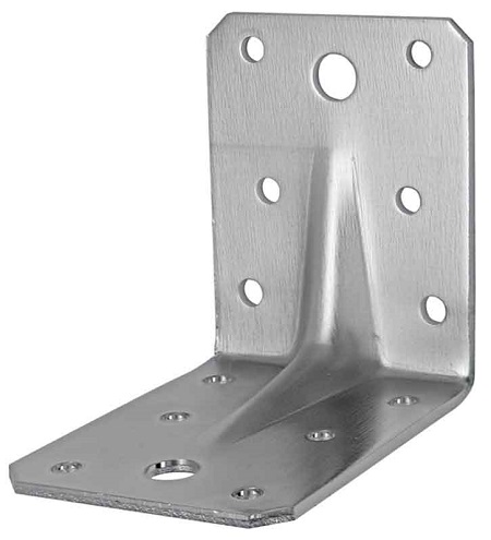
Thus, in all three options The following rule is observed: one edge of the rafter is installed on a sliding support that allows you to rotate. Other on a hinge, which allows only a turn. The mounting of the rafter feet on the sliders is installed using a variety of designs. Most often, they are performed using mounting plates. Also, the fastening with nails, screws, with the use of overhead bars and boards is not excluded. It is only necessary to correctly choose the type of fastener, which will prevent the sling of the rafter foot in the support.
How to calculate rafylas
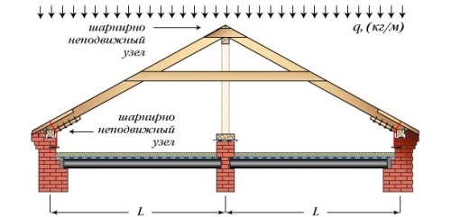
In the process of calculating the rafter design, as a rule, adopt "idealized" calculation scheme. Based on the fact that a certain uniform load will be pressed onto the roof, that is, equal and the same force that acts uniformly on the planes of the skates. In the reality of the uniform load on all the roofs of the roof there is no roof. So, the wind outlines the snow on some skates and blows away from others, the sun melts from some skates and does not get to the rest, the same situation with landslides. All this makes load on the skates completely uneven, although it may not be noticeable. However, even with an unevenly distributed load, all three above the listed variant of the rafting fasteners will remain statically stable, but only under one condition - rigid connection of the skate run. In this case, the run either refrease with the withdrawal rapid legs, or introduced into the frontones of the wall panels of the holmic roofs. That is, the rafter design will remain stable only if the run of the skate is firmly attached from a possible horizontal displacement.
In the case of the manufacture of a forcep roof and the run of the run only on the rack, without support on the walls of the fronts, the situation worsens. In the variants at number 2 and 3, with a reduction in the load on any scope, opposite the calculation on the opposite skate, the roof may be moved to the other side where the load is greater. The very first option, when the bottom of the rafter foot is made with a wrist of the teeth or with the bruke of the bacage of support, while the top of the horizontal is laid on the run, it will be good to keep the uneven load, but only under the condition of the perfect vertical racks that hold the skunk run.
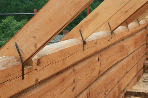
In order to make stability rafters, the system includes a horizontal battle. It is slightly, but still increases stability. That is why in those places where the battle is intersecting with racks, it is fixed with nailting. The assertion that the fight always works only on stretching, is not true in the root. Fight is a multifunctional element. So, in the failure of a rafter design, it does not work in the absence of snow on the roof, or only works on compression when a minor uniform load appears on the skates. For stretching, the design works only when drawdown or when the ridge is deflected under the action of maximum load. Thus, the fight is an emergency element of a rafter structure, which comes into operation when the roof is littered with a large number of snow, the skunk run will be flashed to the maximum calculated value, or uneven unforeseen foundations of the foundation will occur. The consequence may be an uneven drawdown of the skate run and walls. Thus, the lower the bouts will be installed, the better. As a rule, they are installed at such a height, so that they would not create obstacles when walking in the attic, that is, at an altitude of about 2 meters.
If in Options 2 and 3, the bottom node of the rowing rafters should be replaced by a sling with a removal of the edge of the rafter foot behind the wall, it will strengthen the design and make it stable statically with completely diverse combinations of the design.
Also one good way To increase the stability of the structure, it is quite a rigid fixing the bottom of the racks that will support the run. They are installed in the method of writhing in a litter and fix with overlap by any available ways. Thus, the bottom node supports the rack turns from a hinged to a knot with a rigid pincation.
From the method of fastening the rafter legs, it does not depend on how to calculate the length of the rafter.
The cross section of kits, due to the development of rather small stresses in them, do not take the calculation of the rafted, and they are taken quite constructively. In order to reduce the size of the elements that are used in the construction process of the rafter design, the grip cross section takes the same size as the rafter legs, and thinner discs can be used. The bouts are installed either with one or two sides of the rafted and fasten them with bolts or nails. Producing the calculation of the cross section of the rafter design, the fights are not taken into account at all, as if they were not at all. The only exception is the screwing of kits to the rafter feet bolts. In this case, the carrying capacity of the wood, due to the weakening of the bolt hole, decreases due to the use of the coefficient of 0.8. Simply put, if there will be holes for the installation of bolted fights in the rafter legs, then the calculated resistance must be taken in the amount of 0.8. When fastening the fights on the rafters only with a nice fight, the weakening of the resistance of the tree tree does not occur.
But it is necessary to make a calculation of the number of nails. The calculation is made on the cut, that is, the bend of nails. For the estimated force, it takes space, which occurs during the emergency position of the rafter design. Simply put, in the calculation of the compounds of the nails of the fight and the rafting leg, the space is introduced, which is missing for standard work rafter system.
The static instability of the rafter infection system is manifested only on those roofs where there is no possibility to install a skate run that protects against horizontal displacement.
In buildings with Valm types of roofs and with frontones of stone or brick, the faded systems rafters are sufficiently stable and in carrying out activities to ensure greater stability there is no need. However, for counterproof designs, structures should still be installed. When installing bolts or spills as fasteners, you should pay attention to the diameter of the holes for them. It must be the same with the diameter of the bolts or a little less. When emergency situation The fight will not work until the clearance between the wall of the opening and the stud is selected.
Please note that in this process, the bottoms of the rafting legs will be trapped at a distance from a few millimeters to several centimeters. This can lead to a shift and scrolling of Maurolalat and to destroy the cornice of the walls. In the case of spacer rafting systems, when Mauerlat is firmly fixed, this process can cause the sliding of the walls.
Speed \u200b\u200bsprings
Rafter making the work on the bending and the transmitting load wall panelsmust have at least two fastened supports.
To calculate this type of rafter systems, we replace the lower supports in the previous schemes with various degrees of freedom to supports with a single degree of freedom - hinged. For this, where they are not, they are nailed to the edges of the rafter feet bars for support. As a rule, a bar is used, the length of which is at least a meter, and the section is about 5 by 5 cm, given the nice connection. In another embodiment, you can arrange a support in the form of a tooth. In the first version of the calculation scheme, when the rafters rests horizontally into the run, the upper ends of the rafter either nails or bolt are sewn. Thus, a hinged support is obtained.
As a result, the calculated schemes are practically not changed. Internal bends and compression voltages remain unchanged. However, the former supports appear spacer. In the upper nodes of each rafter, the opposite directional space occurs from the end of another rafting leg. Thus, it does not cause special hassle.
The edges of the rafters that rest in each other either through the run may be checked on crumpled material.
In the rapid spacer systems, the purpose of the fight is other - in emergency situations it works for compression. In the process of work, it reduces the stretch on the walls of the edge of the rafter, but it does not completely exclude it. It is completely able to remove it, if he enaches at the very bottom, between the edges of the rafter feet.
Please note that the use of space-sprinkled rafting structures requires careful accounting for the impact of the strength of the pressure on the walls. Reduce this stretch is possible by installing hard and durable skate runs. It is necessary to try to increase the rigidity of the run by installing the racks, console beams or pods, or build a building rise. Especially important is for houses from a bar, chopped logs, light concrete. Concrete, brick and panel houses It is much easier to carry the power to the walls on the walls.
Thus, the rafter design embedded by the spacer is statically stable at various combinations of loads, it does not require hard mounting of Maurolat to the wall. In order to keep the space, the walls of the building should be massive, equipped with a monolithic reinforced concrete belt around the perimeter of the house. In the event of an emergency, inside the spacer system, which works on compression, the position does not save the position, but only partially reduce the space that is transmitted to the walls. It is in order to have an emergency that would have happened, it is necessary to take into account all the loads that can act on the roof.
Thus, whatever form is not chosen to the roof of the house, the entire rafter system should be calculated in such a way that would satisfy the provisions of reliability and strength. Make a complete analysis of the rafter design - it's not easy. By calculating wooden rafters, it is necessary to include a large number of different parameters, including spacer, bending, possible weight loads. For more reliable arrangement of the rafter system, it is possible to establish more appropriate attachment methods. At the same time, the dimensions of the rafter should not be taken, without making a complete analysis of their technical and functional abilities.
Calculation of the cross section of the Stropyl
The cross section of rafting beams is selected taking into account their lengths and the load.
So, a bar is up to 3 meters long, selected with a diameter of a section of 10 cm.
Bar, up to 5 meters long, - with a cross section diameter of 20 cm.
Bar, up to 7 meters long - with a cross section diameter up to 24 cm.
How to calculate rafters - example
Dan two-storey house 8 to 10 meters in size, the height of each floor is 3 meters. The roofs are chosen wavy asbestos-cement sheets. The roof is double, the support racks of which are located along the central bearing wall. The step of rafted 100 cm. It is required to pick up the length of the rafter.
How to calculate the length of the rafted? As follows: the length of the rafter feet can be chosen so that they would lay three rows slate sheets. Then the required length: 1.65 x3 \u003d 4.95 m. The roof slope in this case will be equal to 27.3 °, the height of the formed triangle, that is, the attic space, 2.26 meters.

1. Calculation of carrier coverage elements
Stropile legs are calculated as freely lying beams on two supports with an inclined axis. The load on the rafter foot is assembled with a cargo area, the width of which is equal to the distance between the rapid legs. The calculated temporal load q should be located on two components: normal to the axis of the rapid leg and in parallel to this axis.
2.1.1. Calculation of clamps
We accept the cutlery of the board with a cross section of 50'50 mm (R \u003d 5.0 kN / m) laid in 250 mm increments. Wood - pine. Step rafted 0.9 m. Roof slope 35 0.
The calculation of the roof crates is carried out on two loading options:
a) Own weight roofing and snow (calculation on strength and deflection).
b) Own weight roofing and focused cargo.
Initial data:
1. Rein the 2nd grade bars with calculated resistance R. U.\u003d 13 MPa and modulus of elasticity E \u003d 1.´ 10 4 MPa.
2. conditions of operation B2 (in the normal zone), m. in=1 ; m. N.=1,2 For mounting load when bending.
3. Purpose of reliability for appointment g. N.=0,95 .
4. Wood condition r. \u003d 500 kg / m 3.
5.Cheeficiency reliability on load from the weight of galvanized steel g. F.=1,05 ; From the weight of Bruckov g. F.=1,1 .
6. Normative weight of snow cover on 1m 2 horizontal projection of the earth surface S. 0 \u003d 2400 N / m 2.

Calculated scheme of the crate
Table 2.1
Load collection on 1mp. Chatters, kn / m
 |
where S. 0 - the regulatory value of the weight of the snow cover on 1 m 2 horizontal
the surface of the Earth taken in Table. 4, for the IV snowy
she is S. 0 \u003d 2.4 kPa;
m. - transition coefficient from the weight of the snow cover of the Earth to
snow load on the coating, received by paragraph 5.3 - 5.6.
When the beam is loaded uniformly distributed load from its own weight and snow, the greatest bending moment is equal to:
![]() KN M.
KN M.
In the corners of the roof of the roof A³10 °, it is taken into account that its own roofing and crates is evenly distributed over the surface (skate) of the roof, and the snow - by its horizontal projection:
M x \u003d M cos a \u003d 0.076 COS 29 0 \u003d 0.066 kN'm
M y \u003d m sin a \u003d 0.076 sin 29 0 \u003d 0.036 kN'm
The moment of resistance:
![]() cm
cm
![]() cm
cm
The strength of bars of the crates is tested taking into account oblique bending according to the formula:
 ,
,
where M X. and M Y. - components of the estimated bending moment relative to the main axes of X and Y.
R y.\u003d 13 MPa
g. N.=0,95
![]() ,
,
The moment of inertia Bruke is determined by the formula:
 cm 4.
cm 4.
 cm 4.
cm 4.
Deflection in the plane perpendicular to the Skate:

 M.
M.
Deflection in the plane parallel to the Skate:

 m,
m,
where E \u003d 10 10 Pa - Wood elastic modulus along the fibers.
Full deflection:
![]() \u003d M.
\u003d M.
Checking the deflection:
where \u003d - the maximum permissible relative deflection determined by the table. sixteen .
When the beam is loaded with its own weight and focused cargo, the greatest moment in the span is:
Check the strength of normal sections:
where R y.\u003d 13 MPa — estimated resistance Wood bending.
g. N.=0,95 - Reliability coefficient for its intended purpose.
The conditions on the first and second combinations are performed, therefore we accept the crate of the cross section of B'h \u003d 0.05'0.05 in a step of 250 mm.
2.1.2. Calculation of rafting legs
Calculate the sleeve rafters from bars with a single-row arrangement of intermediate supports under the roof of oscil. kr. iron. The base of the roof serves a doomlet of bars with a cross section of 50 50 mm in increments \u003d 0.25 M.. Step of rafter foot \u003d 1.0 M.. Material for all wooden elements - pine 2nd grade. Operating conditions - B2.
Construction area - Vologda.
Estimated scheme of the rafter
|
Bruks of the crates are located on the rafter legs that are lower
ends are based on Mauerlates (100 100), laid on the inner edge of the outer walls. In the skate node of the rafter, two milk overlays are fastened. To repay the rollers, the rafting legs are pulled by the Rigel - two paired boards. The angle of inclination of the roof 29 0.
We produce a collection of loads per 1 m 2 of the inclined surface of the coating, data in Table 2.2.
Table 2.2.
Load collection on 1mp. Stropile foot, kN / m
where S. 0 - The normative value of the weight of the snow cover on 1 m 2 of the horizontal surface of the Earth, received in Table. SNIP 4, for the IV snow area S. 0 \u003d 2.4 kPa;
m. - The transition coefficient from the weight of the Earth's snow cover to the snow load on the coating, received by paragraph 5.3 - 5.6.
We produce static calculation of the rafter foot as a two-span beam loaded uniformly distributed load. Dangerous cross section of the rafter foot is the cross section on the middle support.
Bending moment in this section:
Vertical pressure at point C equal to the right reference reaction of the two-ranking beam is:
 \u003d 0.265 kN
With a symmetrical load of both skates, vertical pressure at the point with doubles: kN.
Enclosing this pressure in the direction of the rafter legs, we find a compressive force at the top of the rafter foot:
 KN
KN
Collectionloads
Previously, to determine the loads, we specify the cross section of the rafter foot 75x225 mm. The constant load on the rafter foot is calculated in Table. 3.2.
Table 3.2 Calculated permanent load on the rafter foot, kPa
|
Operation- |
Limit |
||
|
Elements and loads |
γ fM. |
value |
|
|
value |
load |
||
|
load | |||
|
Slinge foot 0.075 * 0,225 * 5 / 0.95 | |||
|
g p. e \u003d 0.372 |
g C Tr. M \u003d 0.403. |
Calculated limit load on the rafter foot (a combination of constant plus snow)
Geometric scheme of timber
Schemes for calculating a rafter foot showing in Fig. 3.2. With the width of the corridor in the axes  \u003d 3.4 m The distance between the longitudinal axes of the outer and inner walls.
Distance between the axes of Mauerlat and Lenzhenny, taking into account the binding to the axis (  \u003d 0.2 m) m. We set the troop at an angle β \u003d 45 ° (bias 2 \u003d 1). The sloping sling is equal to the roof of the roof I 1 \u003d i \u003d 1/3 \u003d 0.333.
To determine the sizes necessary for calculating, you can draw the geometric scheme of the rafter on the scale and measure the range of the line. If Maurylalat and Liezhalan are on the same level, the rafter spans can be determined by formulas

Heights of nodes H 1 \u003d i 1 l. 1 \u003d 0.333 * 4.35 \u003d 1.45 m; H 2: \u003d I 1 l.\u003d 0.333 * 5.8 \u003d 1.933 m. Height mark: Rigel taking 0.35 m below the intersection point of the axes of the rafter and racks h. = h. 2 - 0.35 (m) \u003d 1,933 -0.35 \u003d 1.583 m.
Efforts in the rafter foot n Rigel
The rafter foot works like a three-role continuous beam. Supported supports can change the supporting moments in continuous beams. If we assume that the bending moment on it becomes zero, then it is possible to conditionally cut the hinge in the zero moment (above the support). To calculate the rafter foot with a certain margin of durability, we believe that the drawdown of the pitch reduced to zero the reference bending moment over it. Then the calculated scheme of the rafter foot will correspond to rice. 3.2, c.
Bending moment in a rafter foot
To determine the returrariness in the rigle (tighten), we believe that the supports seen in such a way that the supporting moment above the troops is equal M. 1 and above the racks - I will. Conditionally cut the hinges in the location of zero moments and we consider the middle part of the rafter as a three-stroken army by a span l. CP \u003d 3.4 m. Run in such an arc is equal
Vertical component of the reaction of the pan
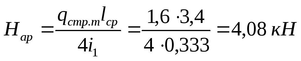
Using the scheme Fig. 3.2.G, we define the effort in the subpatch
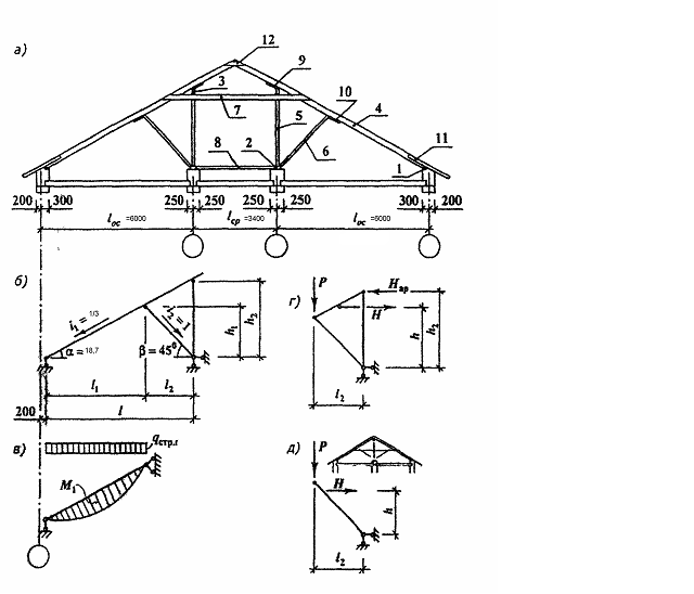 Fig. 3.2. Schemes for calculating rafters
a-transverse section of the attic coating; b -sham to determine the calculated length of the rafting leg; B - the calculated scheme of the rafter foot; r - scheme to determine the returrariness in the rigle; l - also for a scheme with one longitudinal wall; 1 - Mauerlat; 2 - Liezhalan; 3 - run; 4 - lumpy leg; 5 - Stretch; 6 - troops; 7 - Rigel (tightening); 8 - strut; 9, 10-vial bars; 11 - the mare; 12 - lining.
Calculation of the rafter foot on the strength of normalsections
The required torque resistance

By arrival M take the width of the rafter foot b = 5 cm and find the required height of the section

By arrival M We accept the board with a cross section of 5x20 cm.
In checking the deflection of the rafter legs, there is no need because it is located in a room with limited access to people.
Calculation of butt boardstropile foot.
Since the length of the rafter leg is greater than 6.5 m, it is necessary to perform it from two boards with a junction in the fastest. We place the center of the joint at the Opportment Place. Then the bending moment in the junction with the drawdown of the pump M 1 \u003d 378.4 kN * cm.
The joint is calculated similarly to the junction of the runs. Take the length of the flaile l. Fask \u003d 1.5 m \u003d 150cm, nails with a diameter d.= 4 mm \u003d 0.4 cm and long l. gv = 100 mm.
Distance between the axes of nail connections
150 -3 * 15 * 0.4 \u003d 132 cm.
The force perceived by the nail joint
Q \u003d m op / z \u003d 378.4 / 132 \u003d 3,29 kN.
The calculated length of pinching the nail taking into account the normalized limit gap between the boards Δ sh \u003d 2 mm with the thickness of the board Δ d \u003d 5.0 cm and the length of the island of the nail L, 5D
a P \u003d. l. gv -δ d -δ w -l, 5d \u003d 100-50-2-1.5 * 4 \u003d 47.4 mm \u003d 4; 74 cm.
In the calculation of the native (nail) compound:
- Thickness of a thinner element a.= a. p. =4,74 cm;
- Thickness of a thicker element C \u003d δ d \u003d 5.0 cm.
Find the attitude a / s \u003d4,74/5,0 = 0,948
By arrival T, we find the coefficient k H \u003d 0.36 kN / cm 2.
We find the carrying ability of one seam of one nail from the conditions:
- crumpled in a thicker element
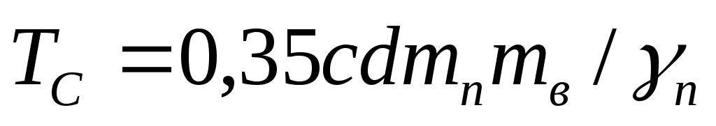 \u003d 0.35 * 5 * 0.4 * 1 * 1 / 0.95 \u003d 0.737 kN
- Crumbles in a thinner element
 \u003d 0.36 * 4.74 * 0.4 * 1 * 1 / 0.95 \u003d 0,718 kN
- Bending nail
=
(2,5* 0,4 2
+ 0,01* 4,74 2)
 / 0,95 \u003d 0,674 kN
- But no more than
Of the four values, choose the smallest T \u003d.0,658 kN.
We find the required number of nails p gv ≥ Q./ T. =2,867/0,674=4,254.
Accept p gv = 5.
Check the ability to install five nails in one row. The distance between the nails across the fibers of the wood S 2 \u003d 4D \u003d 4 * 0.4 \u003d 1.6 cm. Distance from the extreme nail to the longitudinal edge of the board S 3 \u003d 4D \u003d 4 * 0.4 \u003d 1.6 cm.
In the height of the rafter h. = 20 cm should fit
4S 2 + 2SZ \u003d 4 * 1,6 + 2 * 1,6 \u003d 9.6 cm<20 см. Устанавливаем гвозди в один ряд.
Calculation of the bolt connection node with a rafter foot
On the assortment (ad. M) We accept the rigle from two boards by cross section bXH. = 5x15 cm each. The effort in the junction is relatively large (H \u003d 12, KN) and may require the installation of a large number of nails in the construction sites. To reduce the labor intensity of the coating installation, we design a bolt connection of the riglel with a rafter foot. We accept bolts with a diameter d \u003d 12 mm \u003d 1.2 cm.
In the rafter foot (bolts) fmines the wood at an angle to the fibers α \u003d 18.7 0. By arrival I find the corresponding angle α \u003d 18.7,7 0 coefficient k α \u003d 0.95.
In the calculation of the magnifying connection, the thickness of the average element is equal to the width of the rafter feet C \u003d 5 cm, the thickness of the extreme element - the width of the rigel board a \u003d.5 cm.
We determine the carrying ability of one seam of one braided from the conditions:
- crumples in the middle element  \u003d 0.5 * 5 * 1.2 * 0.95 * 1 * 1 / 0.95 \u003d 3.00 kN
- Crumbles in the extreme element  \u003d 0.8 * 5 * 1,2 * 1 * 1 / 0.95 \u003d 5.05 kN;
- Bend bending \u003d (L, 8 * 1.2 2 + 0.02 * 5 2)  / 0,95 \u003d 3.17 kN
- but no more than
Of the four values, we choose the smallest T \u003d 3.00 kN.
Determine the required number of aging (bolts) with the number of seams N sh \u003d 2

We accept the number of bolts N h \u003d 3.
In checking the cross section of the rigleel, there is no need for strength because it has a large margin of safety.
4. Ensuring spatial rigidity and geometric unambiguous building


