SNiP 2.06.08-87
BUILDING REGULATIONS
Concrete and reinforced concrete structures
hydraulic structures
Date of administration 1988-01-01
Developed by VNIIG them. B. E. Vedeneeva of the USSR Ministry of Energy (Cand. Tech. Science A. P. Pak - Head of Works; A. V. Karavaev; Tech candidates. Sciences A. D. Kaufman, M. S. Lamkin. A. N. Marchuk, L. P. Trapeznikov, V. B. Sudakov; Doctor Tehn. Sciences L. A. Gordon, I. B. Sokolov) together with the hydroproprotection. S. Ya. Zhuka Midnergo of the USSR (A. G. Okolkov, T. I. Sergeeva; Dr. Tekhn. Sciences S. A. Frid; S. A. Berezinsky); CargoEGS Ministry of Energy of the USSR (Dr. Tech. Sciences G. P. Verbitsky); Higrorechetrans Ministry of Finrechflot RSFSR (Cand. Tech. Sciences V. E. Durirevsky); LenmoriniProject of the USSR Mormorflut (Cand. Tech. Sciences A. A. Dolinsky): To the Soyuz Lamodroduct of the Ministry of Economic Development of the USSR (Cand. Tech. Sciences S. 3. Ragolsky).
Made by the USSR Ministry of Energy.
Prepared for approval by the management of standardization and technical standards in the construction of the USSR State Building (D. V. Petukhov).
Approved by Decree of the USSR State Construction Committee of February 26, 1987. № 37.
With the introduction of SNIP 2.06.08-87 "Concrete and reinforced concrete structures of hydraulic structures" from January 1, 1988, SNIP II-56-77 "concrete and reinforced concrete structures of hydraulic structures" are lost.
In SNiP 2.06.08-87, "concrete and reinforced concrete structures of hydraulic structures" made corrections of typos published in BST No. 1 of 1989.
Corrections made by the Legal Bureau "Codex".
These norms apply to the design of newly under construction and reconstructed concrete and reinforced concrete structures of hydraulic structures that are constantly or periodically under the influence of the aquatic environment.
Elements of concrete and reinforced concrete structures of hydraulic structures that are not exposed to an aquatic environment should be designed in accordance with the requirements of SNiP 2.03.01-84; Concrete and reinforced concrete structures of bridges, transport tunnels and pipes located under the mighty of automotive and railways, It should be designed on SNiP 2.05.03-84.
In the projects of structures designed for construction in seismic areas in the northern construction and climatic zone, in areas of distribution of sediments, swelling and weak on the physicomechanical properties of soils, additional requirements for such structures with relevant regulatory documents approved or agreed by the Gosstroke must be respected THE USSR.
The main letter denotes and their indices adopted in these standards in accordance with Art CEV 1565-79 are provided in the reference application 1.
1. GENERAL PROVISIONS
1.1. When designing concrete and reinforced concrete structures of hydraulic structures, it is necessary to comply with the requirements of SNIP 2.06.01-86 and construction standards and rules for the formation of certain types of hydraulic structures.
1.2. The choice of the type of concrete and reinforced concrete structures (monolithic, collected-monolithic, prefabricated, including pre-intense and covers in the base) must be made on the basis of the conditions for the technical and economic expediency of their application in specific construction conditions, taking into account the maximum decrease in material consumption, energy intensity, complexity and Cost of construction.
When choosing elements of prefabricated structures, pre-stressed structures from high-strength concrete and reinforcement, as well as structures of light concrete, should be considered.
Types of structures, the main dimensions of their elements, as well as the degree of saturation of reinforced concrete structures by reinforcement, must be taken on the basis of a comparison of technical and economic indicators of options.
1.3. Elements of prefabricated structures must meet the conditions of mechanized manufacturing on specialized enterprises.
It is necessary to consider the feasibility of the consolidation of prefabricated structures, taking into account the conditions for their manufacture, transportation, carrying capacity of the installation mechanisms.
1.4. For monolithic structures, unified dimensions should be provided to apply inventory formwork.
1.5. The designs of nodes and connections of elements in prefabricated structures should ensure reliable transmission of effort, the strength of the elements themselves in the joint zone, as well as the connection of the additionally laid concrete in the joint with concrete design.
1.6. When designing structures of hydraulic structures, insufficiently tested design and construction practices, for the complex conditions of static and dynamic design of structures (when the nature of the intense and deformed state with the necessary reliability cannot be determined by the calculation) studies should be conducted.
1.7. To ensure the required waterproof and frost resistance of structures, as well as to reduce the counterproofing of water in their settlement sections, it is necessary to provide for the following activities:
laying the concrete of the corresponding stamps on waterproof and frost resistance from the pressure of the pressure and the outer surfaces (especially in the zones of variable water level);
the use of surface-active additives to concrete (air-dye, plasticizing, etc.);
waterproofing and thermal hydrogenation of external surfaces of structures;
compression of concrete from the head of pressure faces and from the surfaces of the structures experiencing stretching from operational loads;
drainage device from the head of the pressure face.
The choice of activities should be made on the basis of a technical and economic comparison of options.
2. Materials for concrete and
Reinforced concrete structures
2.1. Concrete for concrete and reinforced concrete structures of hydraulic structures must meet the requirements of GOST 26633-85 and this section.
2.2. When designing concrete and reinforced concrete structures of hydraulic structures, depending on the type and working conditions, it is necessary to establish the quality of concrete indicators, the main of which are the following:
a) Concrete classes for compression strength, which correspond to the value of the guaranteed strength of concrete, MPa, with the security Q \u003d 0.95. In massive structures, the use of concrete with the values \u200b\u200bof guaranteed strength with the security Q \u003d 0.9 is allowed.
In projects it is necessary to provide for the following classes of concrete on compressive strength: B5, B7.5, B10, B12.5, B15, B20, B25, B30, B35;
b) Concrete classes for durability of axial stretching. This characteristic is established in cases where it has a dominant value and is monitored in production.
In projects it is necessary to provide for the following classes of concrete based on axial stretching:
c) brand concrete on frost resistance.
The projects need to provide for the following brands of concrete on frost resistance: F50, F75, F100, F150, F200, F300, F400, F500, F600.
The brand of frost resistance concrete should be prescribed depending on the climatic conditions and the number of estimated cycles of alternate freezing and thawing during the year (according to long-term observations), taking into account operating conditions. For energy facilities, the brand of concrete on frost resistance should be taken in Table. one.
Table 1
|
Climatic conditions |
Brand concrete on frost resistance with the number of alternate freezing and thawing cycles per year |
|||||
|
up to 50 included. |
St. 50 to 75 |
St. 75 to 100 |
St. 100 to 150 |
St. 150 to 200 Enable. |
||
|
Moderate |
||||||
|
Especially severe |
||||||
Notes: 1. Climatic conditions are characterized by the average monthly temperature of the coldest month: moderate, above minus 10 ° С harsh - from minus 10 to minus 20 ° C included., Especially severe - below minus 20 ° C.
2. The average monthly temperatures of the coldest month for the construction area are determined by SNiP 2.01.01-82, as well as according to the Hydrometeorological Service.
3. With the number of calculated cycles, more than 200 should apply special types of concrete or constructive heat protection;
d) brand of concrete on waterproof.
In projects it is necessary to provide for the following brands of concrete on waterproof: W2, W4, W6, W8, W10, W12, W16, W18, W20.
The brand of concrete on waterproofs is prescribed depending on the pressure gradient, defined as the ratio of the maximum pressure in meters to the thickness of the structure (or the distance from the pressure edge to the drainage) in meters, and the temperature in contact with the construction of water, in the table. 2, or depending on the aggressiveness of the medium in accordance with SNiP 2.03.11-85.
In extensive-resistant pressure reinforced concrete structures and in the emitting-resistant non-pressure structures of marine structures, the design brand of concrete on waterproof should not be lower than W4.
table 2
|
Water temperature. |
Brand concrete on waterproof in the head gradients |
|||
|
up to 5 included. |
sv. 10 to 20. |
sv. 20 to 30 included. |
||
|
Up to 10 included. |
||||
|
St. 10 to 30 turn on. |
||||
Note. For structures with a pressure gradient, over 30, it is necessary to assign a concrete brand on W16 waterproof and above.
2.3. With proper justification, it is allowed to establish intermediate values \u200b\u200bof concrete classes by compressive strength, differ from those listed in clause 2.2, as well as classes B40 and higher. Characteristics of these concrete should be taken on SNIP 2.03.01-84 and in interpolation.
2.4. The concrete of the structures of hydraulic structures should be made additional, established in projects and confirmed by experimental studies, the requirements: for limiting extension, the absence of harmful interaction of cement alkalis with fillers, resistance to the abrasion of water with bottom and suspended nanos, resistance to cavitation and chemical impact, heat dissipation when Concrete hardening.
2.5. The period of hardening (age) of concrete, corresponding to its classes on compressive strength, on axial stretching and brand of waterproof, is taken, as a rule, for the designs of river hydraulic structures 180 days, for the prefabricated and monolithic structures of marine and river port facilities 28 days. The period of hardening (age) of concrete, corresponding to its design brand for frost resistance, is taken by 28 days, for massive structures, built in warm formwork, 60 days.
If the timing of the actual loading of structures, methods of their construction, the conditions of the concrete, the form and quality of the cement used are known, then the concrete class is allowed to be installed.
For prefabricated, including pre-stressed structures, the vacation strength of concrete concrete should be taken in accordance with GOST 13015.0-83, but not less than 70% of the strength of the adopted concrete class.
2.6. For reinforced concrete elements from heavy concrete, calculated on the impact of repeatedly repeated loads, and reinforced concrete squeezed rod structures (embankments of the type of overpass on piles, piles-shells, etc.) Apply a concrete class by compressive strength not lower than B15.
2.7. For precompanied elements, a concrete class should be taken by compressive strength: not less than B15 - for structures with rod reinforcement; Not less than B30 - for elements immersed in a ground by a bog or vibration.
2.8. To deploy the joints of the elements of prefabricated structures, which during operation can be exposed to negative temperatures Outdoor air or the effects of aggressive water, it is necessary to use concretes of design stamps on frost resistance and waterproof not lower than those adopted for jackets.
2.9. The widespread use of additives of surfactants (SDB, STB, LHD, etc.), as well as the use of thermal power plants as an active mineral additive, which meets the requirements of the relevant regulatory documents.
2.10. If, for technical and economic calculations, it is advisable to use concrete on straining cement to increase the waterproof of concrete and reinforced concrete structures of hydraulic structures, and to reduce the load from its own weight of the structure - light concrete, then classes and brands of such concrete should be taken on SNiP 2.03.01-84.
2.11. Regulatory and calculated resistance of concrete depending on the classes of concrete for compressive strength and on axial stretching should be taken in Table. 3.
In the case of adoption of intermediate classes of concrete, regulatory and calculated resistance should be taken in interpolation.
2.12. The coefficients of the working conditions of concrete should be taken in Table. four.
2.13. When calculating reinforced concrete structures on the endurance of the calculated resistance of concrete and should be multiplied by the coefficient of working conditions received by table. five.
2.14. Calculated concrete resistance with comprehensive compression, MPa, should be determined by the formula
![]() (1)
(1)
Table 3.
|
Regulatory and calculated resistance concrete, MPa (kgf / cc.) |
||||||
|
Class concrete |
regulatory resistance; Estimated resistance for the limit states of the second group |
estimated resistance for the limit states of the first group |
||||
|
tension axial |
compression axial (prism strength) |
tension axial |
||||
|
By compressive strength |
||||||
|
Tensile strength |
||||||
where - the coefficient taken on the basis of the results of experimental studies; With their absence for concrete classes for compression strength B15, B20, B25, the coefficient is allowed to determine by the formula
The lowest in the absolute value of the main stress, MPa;
The coefficient of effective porosity.
Table 4.
|
Factors resulting in the introduction of coefficients of the working conditions of concrete |
Concrete Condition Coefficients |
|
|
symbol |
value |
|
|
Special combinations of loads for concrete structures |
||
|
Multiple load repetition |
See Table. five |
|
|
Reinforced concrete structures |
||
|
Concrete structures: |
||
|
especially compressed elements that are not exposed to an aggressive medium and not perceive water pressure, calculated without taking into account the resistance of the stretched cross section zone |
||
|
other concrete elements |
||
|
The effect of a two-axis complex intense state compression-stretching on concrete strength |
||
Note. If there are several factors acting simultaneously, the product is introduced into the calculation of the relevant work coefficients. The product must be at least 0.45.
For structures I and II classes, the coefficient should be determined experimentally. In the absence of experimental data, the coefficient is allowed to take equal: when; for
2.15. The initial modulus of the elasticity of the concrete of massive structures in compression and tension should be taken in Table. 6.
When calculating the strength and deformations of thin-walled rod and slab elements, the elastic modulus of concrete should be taken in all cases by table. 6 As for concrete with the maximum diameter of a large aggregate 40 mm and a sediment of a cone, equal to 8 cm and more.
Module of the elasticity of concrete subjected to accelerating the hardening of thermal processing at atmospheric pressure or in autoclaves, it should be accessed by SNiP 2.03.01-84.
Concrete shift module should be taken equal.
The initial transverse deformation coefficient (Poisson coefficient) V is accepted equal: for massive structures - 0.15, for rod and slab structures - 0.20.
The density of heavy concrete in the absence of experienced data is allowed to be taken equal to 2.3-2.5 t / cubic meters.
Armature
2.16. For reinforcing reinforced concrete structures of hydraulic structures, reinforcement steel should be applied, which meets the requirements of the relevant state standards or approved in the prescribed manner of technical conditions and belonging to one of the following types:
rod reinforcement steel:
hot rolled - smooth class A-I, periodic profile classes a-iI, A-III, A-IV, A-V; thermally and thermomechanically hardened - periodic profile of the class at-IIIs, AT-IVC, AT-VCK;
strengthened class A-IIV;
wire reinforcement steel:
hopotted Wire Ordinary - Periodic Profile of Class BP-I.
Table 5.
|
Condition of concrete on humidity |
Coefficients of concrete working conditions repeated load and the asymmetry coefficient of the cycle ,. equal |
|||||||
|
Natural humidity |
||||||||
|
Watery |
||||||||
Notes: 1. The coefficient for concrete, the brand of which is set at the age of 28 days, is taken in accordance with the requirements of SNiP 2.03.01-84.
2. The coefficient is:
![]() ,
,
where and is now the smallest and most voltage in Betoon within the load change cycle.
Table 6.
|
The initial modules of the elasticity of concrete during compression and stretching, MPa (kgf / sq. cm), |
||||||
Continuing Table 6.
|
OCADKA cone concrete mix, cm |
Maximum size of large aggregate, mm |
The initial modules of the elasticity of concrete during compression and stretching, MPa (kgf / sq. cm), when grade concrete for compressive strength |
|||
For mortgage parts and connecting linings, it should be used, as a rule, rolling carbon steel.
Marks of reinforcement steel for reinforcement of reinforced concrete structures depending on the conditions of their operation and the average temperature of the outside air of the coldest five days in the construction area should be taken on SNiP 2.03.01-84, and for port and transport structures also on SNiP 2.05.03-84.
The reinforcement steel classes A-IIIV, A-IV and A-V are recommended for pre-stressed structures.
2.17. The regulatory and calculated resistances of the main types of reinforcement used in the reinforced concrete structures of hydraulic structures, depending on the class of fittings should be taken in Table. 7.
When calculating the valves on the main tensile stresses (beam-walls, short consoles, etc.) the estimated reinforcement resistance should be taken as for longitudinal reinforcement to the action of the bending moment.
With a proper justification for reinforced concrete structures of hydraulic structures, it is allowed to use the rod and wire fittings of other classes. Their regulatory and calculated characteristics should be accessed by SNiP 2.03.01-84.
2.18. The coefficients of the working conditions of unprinted reinforcement should be taken in Table. 8, and strained fittings - SNIP 2.03.01-84.
The coefficient of conditions for the operation of the reinforcement in the calculation of the limit states of the second group is taken equal to one.
2.19. The estimated resistance of an unprepared stretched rod fittings when calculating endurance should be determined by the formula
where - the coefficient of working conditions, which is determined by: for the assembly of class A - I, A-II, A-III - according to formula (4), and for other classes of reinforcement - on SNiP 2.03.01-84.
 , (4)
, (4)
here - the coefficient, taking into account the class of fittings taken in Table. nine;
The coefficient, taking into account the diameter of the reinforcement, received in Table. 10;
The coefficient that takes into account the type of welded joint received by Table. eleven;
The asymmetry coefficient of the cycle, where and is the smallest and largest voltage in the stretched fittings.
Stretching fittings for endurance does not conduct if the coefficient determined by formula (4) is greater than the unit.
Table 7.
|
View and class of fittings |
Regulatory resistance to stretching and calculated resistance to stretching of reinforcement for the limit states of the second group, MPa (kgf · sq. CM) |
Estimated reinforcement resistance for the limit states of the first group, MPA (kgf / sq. CM) |
||
|
stretching |
||||
|
longitian |
transverse (clamps, bent rods) |
|||
|
Student valve classes: |
||||
|
A-III, diameter, mm: |
||||
|
Hardened Class A-III with Control: |
||||
|
voltages and elongation |
||||
|
only elongation |
||||
|
Wire fittings class BP-I, diameter, mm: |
||||
* In welded frames for clamps from class A-III reinforcement, the diameter of which is less than 1/3 of the diameter of the longitudinal rods, is 255 MPa (2600 kgf / sq. Cm).
In the absence of adhesion of reinforcement with concrete is zero.
When calculating building structures, you need to know the calculated resistance and the elastic module for one or another material. These main building materials are presented here.
Table 1. Modules of elasticity for the main building materials
| Material |
Elastic modulus E, MPa |
Cast iron white, gray | (1.15 ... 1.60) · 10 5 |
| Cast iron puffy | 1.55 · 10 5 |
| Carbon steel | (2,0 ... 2,1) · 10 5 |
| Alloy steel | (2,1 ... 2,2) · 10 5 |
| Copper rolling | 1.1 · 10 5 |
| Copper cold-drawn | 1.3 · 10 3 |
| Copper cast | 0.84 · 10 5 |
| Bronze phosphorous catanny | 1,15 · 10 5 |
| Bronze manganese catanna | 1.1 · 10 5 |
| Aluminum aluminum bronze | 1,05 · 10 5 |
| Brass cold-drawn | (0.91 ... 0.99) · 10 5 |
| Cathedral brass | 1.0 · 10 5 |
| Aluminum rod | 0.69 · 10 5 |
| Aluminum wire stretched | 0,7 · 10 5 |
| Duralumin Katha | 0.71 · 10 5 |
| Zinc Kanden | 0.84 · 10 5 |
| Lead | 0.17 · 10 5 |
| Ice | 0.1 · 10 5 |
| Glass | 0.56 · 10 5 |
| Granite | 0.49 · 10 5 |
| Lime | 0.42 · 10 5 |
| Marble | 0.56 · 10 5 |
| Sandstone | 0.18 · 10 5 |
| Masonry | (0.09 ... 0,1) · 10 5 |
| Brick Stone Masonry | (0.027 ... 0,030) · 10 5 |
| Concrete (see Table 2) | |
| Wood along fibers | (0.1 ... 0.12) · 10 5 |
| Wood across fibers | (0.005 ... 0,01) · 10 5 |
| Rubber | 0.00008 · 10 5 |
| Textolit | (0.06 ... 0,1) · 10 5 |
| Getinax | (0.1 ... 0.17) · 10 5 |
| Bakelite | (2 ... 3) · 10 3 |
| Celluloid | (14.3 ... 27,5) · 10 2 |
Regulatory data for calculating reinforced concrete structures
Table 2. Concrete elastic modules (according to SP 52-101-2003)
Table 2.1 Concrete elastic modules according to SNiP 2.03.01-84 * (1996)
Notes:
1. Above the line shows the values \u200b\u200bin the MPa, under the line - in kgf / cm & sup2.
2. For lightweight, cellular and porous concrete at intermediate values \u200b\u200bof concrete density, the initial moduli of elasticity is taken by linear interpolation.
3. For cellular concrete of non-autoclave hardening, the value of E B is taken as for autoclave hardening concrete with multiplication by the coefficient of 0.8.
4. For straining concrete, E B value is taken as for heavy concrete with multiplication by the coefficient
a. \u003d 0.56 + 0.006V.
Table 3. Regulatory values \u200b\u200bof concrete resistance (according to SP 52-101-2003)
Table 4. Estimated values \u200b\u200bof concrete resistance compression (according to SP 52-101-2003)
Table 4.1. The calculated values \u200b\u200bof the resistance of the concrete compression according to SNiP 2.03.01-84 * (1996)

Table 5. Estimated values \u200b\u200bof concrete resistance stretching (according to SP 52-101-2003)
Table 6. Regulatory resistance for reinforcement (according to SP 52-101-2003)
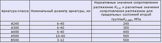
Table 6.1. Regulatory resistance for class A reinforcement according to SNiP 2.03.01-84 * (1996)
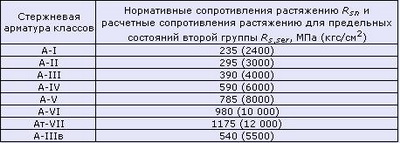
Table 6.2. Regulatory resistance for assembly of classes in and k according to SNiP 2.03.01-84 * (1996)
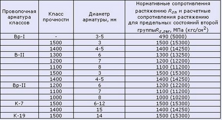
Table 7. Estimated resistance for reinforcement (according to SP 52-101-2003)

Table 7.1 Estimated resistance for class A reinforcement according to SNiP 2.03.01-84 * (1996)
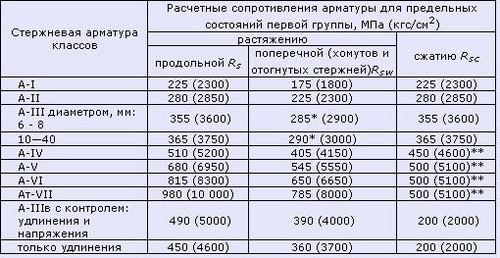
Table 7.2. Estimated resistance for assembly classes in and k according to SNiP 2.03.01-84 * (1996)

Regulatory data for the calculations of metal confouctions
Table 8. Regulatory and calculated resistance when stretching, compression and bending (according to SNiP II-23-81 (1990)) sheet, broadband universal and shaped rolled steel according to GOST 27772-88 for steel structures of buildings and structures

Notes:
1. Through the thickness of the shaped rolled, the shelf thickness should be taken (its minimum thickness is 4 mm).
2. For regulatory resistance, the normative values \u200b\u200bof the yield strength and temporal resistance according to GOST 27772-88 are adopted.
3. The values \u200b\u200bof the calculated resistance are obtained by dividing the regulatory resistance to the reliability coefficients by material, with rounding up to 5 MPa (50 kgf / cm & sup2).
Table 9. Steel brands replaced by steel according to GOST 27772-88 (according to SNiP II-23-81 (1990))

Notes:
1. Steel C345 and C375 Categories 1, 2, 3, 4 according to GOST 27772-88 Replace steel categories, respectively, 6, 7 and 9, 12, 13 and 15 according to GOST 19281-73 * and GOST 19282-73 *.
2. Steel C345K, C390, C390K, C440, C590, C590K according to GOST 27772-88 Replace the corresponding brands of steel categories 1-15 according to GOST 19281-73 * and GOST 19282-73 *, specified in this table.
3. Replacing steels according to GOST 27772-88 with steel supplied according to other state all-union standards and specifications, not provided.
The calculated resistance for steel used for the production of profiled sheets here is not shown.
If briefly, the following concrete brands are recommended for the following building structures:
- sweeping or base preparation for monolithic design - B7.5;
- foundations - not lower than B15, but in some cases a waterproof brand should not be lower than W6 (concrete B22,5). Also, according to the not yet adopted annex D to SP 28.13330.2012, the class of concrete for foundations should be no less than B30. I recommend using a concrete with a waterproof brand not lower than W6, which will ensure the durability of the design;
- Walls, columns and other structures located on the street - Mark for frost resistance not lower than F150, and for the area with the calculated temperature of the outer air below -40С - F200.
— interior wallsBearing columns - by calculation, but not lower than B15, for highly compressed not lower than B25.
Maybe I do not enhance all the standards where the requirements for the selection of the brand of concrete can be spelled, so I ask you to unsubscribe if there is inaccuracies.
The main normalized and controlled indicators of the quality of concrete are:
- class by strength to compression B;
- class for durability on axial stretching B T.;
- brand for frost resistance F;
- brand of waterproof W;
- Magna for medium density D.
B.
The class of concrete on compressive strength B corresponds to the value of the cube strength of concrete on compression in MPa with the security of 0.95 (regulatory cube strength) and is taken from b 0.5 to b 120.
This is the main parameter of concrete, which determines its compression strength. For example, the Class of concrete B15 means that after 28 days at a temperature of 20 ° C, concrete strength will be 15 MPa. However, in the calculations use another digit. Calculated concrete resistance (R b) Compression can be found in Table 5.2 SP 52-101-2003
Table 5.2 SP 52-101-2003
| View of resistance | The calculated values \u200b\u200bof concrete resistance for the limit states of the first group R B.and R Bt. | ||||||||||
| AT 10 O'CLOCK | B15 | IN 20 | B25 | B30. | B35 | B40. | B45. | B50 | B55 | B60 | |
| R B. | 6,0 | 8,5 | 11,5 | 14,5 | 17,0 | 19,5 | 22,0 | 25,0 | 27,5 | 30,0 | 33,0 |
| Tension axial R Bt. | 0,56 | 0,75 | 0,9 | 1,05 | 1,15 | 1,3 | 1,4 | 1,5 | 1,6 | 1,7 | 1,8 |
Why is the strength measured in 18 days? Because Concrete is gaining strength all his life, but after 28 days the strength increase is not so big. One week after filling the strength of the concrete can be 65% of the normative (depends on the temperature of the hardening), in 2 weeks there will be 80%, after 28 days the strength will reach 100%, after 100 days there will be 140% of the regulatory. When designing, there is a concept of strength in 28 days, and it is accepted for 100%.
Also known classification on the brand of concrete M and numbers from 50 to 1000. The figure indicates the compressive strength in kg / cm². The difference in the class of concrete B and the brand of concrete M is in the method of determining the strength. For concrete brand it average value Compression forces during testing after 28 days of sample shutter speed, expressed in kg / cm². This strength is provided in 50% of cases. Concrete class B guarantees concrete strength in 95% of cases. Those. Concrete strength varies and depends on many factors, it is not always possible to achieve the desired strength and there are deviations from design strength. For example, the M100 concrete brand provides concrete strength after 28 days in 100 kg / cm² in 50% of cases. But for the design, it is somehow too little, so the concept of concrete is introduced. Concrete B15 guarantees a strength of 15 MPa after 28 days in 95% of cases.
In the project documentation, concrete is indicated only by the class B, but in construction practice the brand of concrete is still applied.
Determine the brand concrete class and vice versa on the following table:
| Concrete class by compressive strength | The average strength of the concrete of this class, kgf / cm² | The nearest brand of concrete on compressive strength | Deviations of the nearest brand of concrete from the average strength of the concrete of this class,% |
|
B3.5 |
45,84 |
M50 |
9,1 |
|
AT 5 |
65,48 |
M75 |
14,5 |
|
B7.5 |
98,23 |
M100 |
1,8 |
|
AT 10 O'CLOCK |
130,97 |
M150 |
14,5 |
|
B12.5 |
163,71 |
M150 |
8,4 |
|
B15 |
196,45 |
M200 |
1,8 |
|
IN 20 |
261,94 |
M250 |
4,6 |
|
B22.5 |
294,68 |
M300 |
1,8 |
|
B25 |
327,42 |
M350 |
6,9 |
|
B27.5 |
360,16 |
M350 |
2,8 |
|
B30. |
392,90 |
M400 |
1,8 |
|
B35 |
458,39 |
M450 |
1,8 |
|
B40. |
523,87 |
M500 |
4,6 |
Concrete class on axial tensile strength B T. Corresponds to the value of concrete strength on axial stretching in MPa with a security of 0.95 (the regulatory strength of concrete) and is accepted in the range from b T. 0.4 to B. T. 6.
It is allowed to take another value of the safety of concrete strength on compression and axial stretching in accordance with the requirements of regulatory documents for individual special types of structures (for example, for massive hydraulic structures).
The brand of concrete on frost resistance F corresponds to the minimum number of cycles of alternate freezing and thawing, withstanding the sample with a standard test, and is taken from F 15 to F 1000.
The concrete brand on waterproof W corresponds to the maximum value of water pressure (MPa · 10 -1), withstanding a concrete sample when tested, and is taken in the range from W 2 to W 20.
The medium density-density mark corresponds to the average value of the volumetric mass of concrete in kg / m 3 and is taken from the distance from D 200 to D 5000.
The marking of concrete on mobility (P) is also found or the cone sediment is indicated. The higher the number n, the concrete is more liquid and it is easier to work with it.
For straining concrete, they are installed on a self-triation brand.
Selection of concrete brands
The minimum concrete class for designs is prescribed according to SP 28.13330.2012 and SP 63.13330.2012.
For any reinforced concrete building structures, the concrete class should be not lower than B15 (p. 6.1.6 SP 63.12220.2012).
For pre-stressed reinforced concrete structures, the concrete class for compression strength should be taken depending on the type and class of strained fittings, but not lower than B20 (p. 6.1.6 SP 63.12220.2012).
The reinforced concrete scarlet from the precast concrete must be made of concrete not lower than CL. B20 (p. 6.8 SP 50-102-2003)
Class of concrete for designs are prescribed according to a strength calculation for technical and economic considerations, for example, on the lower floors of the building, the monolithic columns have greater strength. The load on them is higher, on the upper floors, the class of concrete decreases, which allows the use of columns of one section on all floors.
There are also recommendations of the SP 28.13330.2012. According to Resolution 1521 of December 26, 2014, Appendix A and D SP 28.13330.2012 is not included in the mandatory list, i.e. Recommended, but I recommend paying your attention to these applications because it is possible that they will be mandatory for use. First of all, it is necessary to make a classification design by an operating environment according to Table A.1 SP 28.13330.2012:
Table A.1 - Operating environment
| Index | Operating environment | Examples of structures |
|
||
| Ho | For concrete Without fittings and mortgage parts: All media, except for the impact of freezing - thawing, abrasion or chemical aggression. For reinforced concrete: dry | Constructions indoors with dry operating mode |
|
||
| Xs1 | Dry and constantly wet environments | Room Designs B. residential buildings, with the exception of kitchens, bathrooms, laundries. Betle constantly under water |
| Xs2 | Wet and briefly dry medium | Concrete surfaces long-wetted water. Foundations |
| Xs3 | Moderately wet environment (wet rooms, wet climate) | Constructions that are often or constantly affected by outer air without atmospheric precipitation. Constructions under a canopy. Construction indoors with high humidity (Public cuisines, Bathrooms, Laundry, Indoor pools, Cattle facilities) |
| Xs4 | Outdoor structures exposed to rain | |
|
||
| In the case when concrete containing steel reinforcement or mortgage parts is subjected to chlorides, including salts used as anti-icers, the aggressive environment is classified according to the following indicators: | ||
| XD1. | Medium with moderate humidity | Constructions exposed to chloride salts aerosol |
| XD2. | Wet and rarely dry operation | Swimming pools. Designs exposed to industrial wastewater containing chlorides |
| XD3. | Alternating Moisturizing and Drying | Bridge designs exposed to spraying with solutions of antifungal reagents. Road covering. Parking overlap |
|
||
| In the case when concrete containing steel reinforcement or mortgage parts is exposed to sea water chlorides or sea water aerosols, the aggressive environment is classified according to the following indicators: | ||
| Xs1 | The effects of aerosols, but without direct contact with sea water | Coastal facilities |
| Xs2 | Under water | Underwater parts of marine structures |
| Xs3 | Zone of tide and lowbow spraying | Parts of marine structures in the variable water level zone |
| Note - for sea water with different chloride content requirements for concrete are listed in Table G.1 | ||
|
||
| Under action on a matured concrete of alternating freezing and thawing, the aggressive medium is classified according to the following features: | ||
| XF1 | Moderate water saturation without anti-icers | Vertical surfaces of buildings and structures with rain and frost action |
| XF2. | Moderate water saturation with anti-icing | Vertical surfaces of buildings and structures subjected to spraying solutions of anti-icers and freezing |
| XF3. | Strong water saturation without anti-icers | Constructions for rain and frost |
| XF4. | Strong water saturation with solutions of anti-icing salts or sea water | Road coatings processed by antifungal reagents. Horizontal surfaces of bridges, the level of external stairs and others. A variable level zone for marine structures under the action of frost |
|
||
| Under the action of chemical agents from the soil, groundwater, the corrosion medium is classified according to the following features: | ||
| H1. | The slight content of aggressive agents is a weak degree of aggressiveness of the environment according to Tables B.1 - V7, G.2 | Designs in underground waters |
| H2. | The moderate content of aggressive agents is the average degree of aggressiveness of the environment according to Tables B.1 - V7, G.2 | Constructions in contact with sea water. Constructions in aggressive soils |
| H3. | The high content of aggressive agents is a strong degree of aggressiveness of the environment according to Tables B.1 - V7, G.2 | Industrial water treatment facilities with chemical aggressive drains. Feeders in animal husbandry. Cooling towers with gas cleaning systems |
|
||
| Depending on the humidity, the medium is classified according to the following features: | ||
| WO. | Concrete is in a dry environment | Designs inside dry rooms. Constructions in outside air Outside precipitation, surface waters and soil moisture |
| WF. | Concrete often or long moisturizes | Outdoor structures that are not protected from exposure to precipitation, surface waters and soil moisture. Construction in wet rooms, such as pools, laundries and other rooms with relative humidity Preferentially, 80%. Construction, often exposed condensate, for example, pipes, heat exchangers, filtering stations Camera, livestock facilities. Massive designs, the minimum size of which exceeds 0.8 m, regardless of moisture |
| WA. | Concrete, which, in addition to the effects of WF environment, act often or for a long alkali, incoming from the outside | Constructions that are exposed to sea water. Construction on which antifungal salts affect without additional dynamic impact (for example, the zone of spraying). Construction of industrial and agricultural buildings (for example, magnifier) \u200b\u200bexposed to alkaline salts |
| WS. | Concrete with high dynamic loads and direct implications of alkalis | Constructions exposed to antifungal salts and additional high dynamic loads (for example, concrete road surfaces) |
| Note - Aggressive impact must be further studied in the case of: the actions of the chemical agents not specified in Tables B.2, B.4, B.3; high speed (more than 1 m / s) flow of water containing chemical agents on Tables B.3 , V.4, V.5. | ||
Depending on the selected operation environment, we assign a concrete class for the design according to Table D.1 SP 28.13330.2012.
Table D.1 - Requirements for concrete depending on the classes of media
| Requirements for concrete | Classes of environments | |||||||||||||||||
| Non-aggressive environment | Carbonization | Chloride corrosion | Freezing - Towing 1) | Chemical corrosion | ||||||||||||||
| Sea water | Other chloride effects | |||||||||||||||||
| Indices environments | ||||||||||||||||||
| Ho | Xs1 | Xs2 | Xs3 | Xs4 | Xs1 | Xs2 | Xs3 | XD1. | XD2. | XD3. | XF1 | XF2. | XF3. | XF4. | H1. | H2. | H3. | |
| Minimum strength class | 15 | 25 | 30 | 37 | 37 | 37 | 45 | 45 | 37 | 45 | 45 | 37 | 37 | 37 | 37 | 37 | 37 | 45 |
| Minimum cement consumption, kg / m 3 | — | 260 | 280 | 280 | 300 | 300 | 320 | 340 | 300 | 300 | 320 | 300 | 300 | 320 | 340 | 300 | 320 | 360 |
| Minimum air content,% | — | — | — | — | — | — | — | — | — | — | — | — | 4,0 | 4,0 | 4,0 | — | — | — |
| Other requirements | — | — | — | — | — | — | — | — | — | — | — | Filler with the necessary frost resistance | Sulphate-resistant cement 2) | |||||
| Required requirements are assigned in columns together with the requirements specified in the following tables. | — | D.2, J.5 | G.1, 2. | G.1, 2. | W.1. | B.1 - V.5, D.2 | ||||||||||||
| 1) To operate in conditions of alternate freezing - thawing concrete should be tested for frost resistance. 2) When the content corresponds to H2 and H3, it is advisable to use sulfate-resistant cement. 3) The values \u200b\u200bof the values \u200b\u200bin this table belong to the concrete at the grade cement 1 according to GOST 30515 and the filler with the maximum size of 20 - 30 mm. | ||||||||||||||||||
If you look at these requirements, then for the foundation you need to take a minimum B30 concrete (XC2 environment). However, while this recommended claims, which in the future, will be mandatory (or will not be, who knows it?)
Selection of concrete brands on waterproof
Brand concrete on waterproof is selected according to Tables B.1-VP 28.13330.2012, depending on the degree of aggressiveness of the medium. Data on the aggressiveness of soils are indicated in engineering and geological surveys and there usually write the recommended stamp on waterproof.
For piles and it is necessary to apply concrete stamps on waterproof not lower than W6 (paragraph 15.3.25 SP 50-102-2003). This brand has concrete B22.5, so it is necessary to take into account when selecting a class of concrete.
For overhead structures subjected to atmospheric influences at the estimated negative temperature of the outer air above minus 40 ° C, as well as for the outer walls of heated buildings, the brand of concrete on waterproof is not normalized (p. 6.1.9 SP 63.13330.2012).
Selection of brand concrete on frost resistance
The selection of brands of concrete on frost resistance is performed according to the tables w.1, w.2 SP 28.13330.2012 depending on the calculated temperature of the outer air.
Table Well.1 - Requirements for concrete of structures working in conditions of alternate temperatures
Table W.2 - Requirements for frost resistance concrete wall structures
| Working conditions of structures | The minimum brand of concrete on the frost resistance of the outer walls of heated buildings from concrete | ||
| Relative indoor air indoor humidity int., % | Estimated winter temperature Outdoor air, ° C | lightweight, cellular, picked | heavy and fine-grained |
| j. int. > 75 | Below -40 | F100 | F200 |
| Below-20 to -40 included. | F75 | F100 | |
| Below -5 to -20 turn on. | F50 | F70 | |
| - 5 and higher | F35 | F50 | |
| 60 < j int. £ 75. | Below -40 | F75 | F100 |
| Below-20 to -40 included. | F50 | F50 | |
| Below -5 to -20 turn on. | F35 | — | |
| - 5 and higher | F25 | — | |
| j. int. £ 60. | Below -40 | F50 | F75 |
| Below-20 to -40 included. | F35 | — | |
| Below -5 to -20 turn on. | F25 | — | |
| - 5 and higher | F15 * | — | |
|
* For light concrete, a frost resistance brand is not normalized. Notes 1. In the presence of steam and waterproofing of the constructions of the brand of concrete on the frost resistance, indicated in the present table, can be reduced by one level. 2. The calculated winter temperature of the outer air is taken according to SP 131.13330 as the temperature of the coldest five days. 3. The brand of the cellular concrete on frost resistance is installed according to GOST 25485. |
|||
The calculated winter temperature of the outer air to calculate reinforced concrete structures is taken by average temperature The air is the coldest five days with the security of 0.98, depending on the construction area according to SP 131.13330.2012.
In soils with a positive temperature, below the level of freezing by 0.5 m, frost resistance is not normalized (SP 8.16 SP 24.13330.2011)
For example, for Moscow, the temperature of the coldest five days with the provision of 0.98 is minus 29 ° C. Then the frost resistance concrete brand is F150 (the characteristic of the mode is a possible episodic effect of temperature below 0 ° C) in a water-saturated state, for example, structures in the ground or under water).
Protective layer of concrete
In order for the reinforcement does not bargain over time, there are requirements for the minimum thickness of the concrete layer to protect fittings. According to the manual for the design of concrete and reinforced concrete structures from heavy concrete without prior voltage of the joint venture SP 52-101-2003, the minimum thickness of the protective layer is determined by Table 5.1 of the AP allowance 52-101-2003:
Table 5.1 AP allowance 52-101-2003
| No. p / p | Conditions for the construction of building structures | The thickness of the protective layer of concrete, mm, not less |
| 1. | In closed rooms at normal and reduced humidity | 20 |
| 2. | In closed rooms with high humidity (in the absence of additional protective events) | 25 |
| 3. | Outdoors (in the absence of additional protective events) | 30 |
| 4. | In the ground (in the absence of additional protective measures), in foundations in the presence of concrete training | 40 |
| 5. | IN monolithic foundations in the absence of concrete training | 70 |
For precast concrete elements, the thickness of the protective layer can be reduced by 5 mm on the data of the table 8.1 SP 52-101-2003 (paragraph 8.3.2).
For buried piles The protective layer of concrete is not less than 50 mm (clause 8.16 SP 24.13330.2011), for boronobiling piles of the foundations of bridges 100 mm.
For boronobiling piles used as protective fences, the protective layer of concrete is taken by 80-100 mm (clause 5.2.12. Methodical manual on the device of fences from burbill piles).
Also in all cases the thickness of the protective layer can not be less than the thickness of the reinforcement.
The protective layer of concrete is considered from the outer surface to the surface of the reinforcement (not to the axis of the valve).
The protective layer of concrete is usually ensured by the use of clamps:

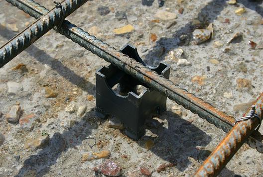
Settlement values \u200b\u200bof concrete resistance
SP 63.13330.2012 Concrete and reinforced concrete structures. Basic provisions
Calculated values \u200b\u200bof concrete resistance axial compression R B.determine by formula 6.1 SP 63.13330.2012:

Settlement values \u200b\u200bof concrete resistance axial stretching R Bt.determine by formula 6.2 SP 63.13330.2012:

The values \u200b\u200bof the reliability coefficient on concrete during compression γ B.take equal:
to calculate the limit states of the first group:
1.5 - for cellular concrete;
The values \u200b\u200bof the reliability coefficient on concrete when tensile γ Bt.take equal:
to calculate the limit states of the first group when appointing concrete class by compressive strength:
1.5 - for severe, fine-grained, straining and lightweight concrete;
2.3 - for cellular concrete;
to calculate the limit states of the first group when appointing concrete class by tensile strength:
1.3 - for heavy, fine-grained, straining and lightweight concrete;
to calculate the limit states of the second group: 1.0.
(clause 6.1.11 SP 63.13330.2012)
In the necessary cases, the calculated values \u200b\u200bof the strength characteristics of concrete are multiplied by the following coefficients of operating conditions γ Bt., considering the peculiarities of the work of concrete in the design (load character, conditions ambient etc.):
a) Γ. B. 1 - for concrete and reinforced concrete structures introduced to the calculated resistance values R B.and R Bt.and taking into account the effect of the duration of the static load:
γ B. 1 \u003d 1.0 with a brief (short) load action;
γ B. 1 \u003d 0.9 with prolonged (long) load action. For cellular and paved concrete γ B. 1 = 0,85;
b) Γ. B. 2 - for concrete structures introduced to the calculated resistance values R B.and taking into account the nature of the destruction of such structures, γ B. 2 = 0,9;
c) Γ. B. 3 - for concrete and reinforced concrete structures concreted in a vertical position with a layer height of concreting over 1.5 m, introduced to the calculated value of concrete resistance R bγ B. 3 = 0,85;
d) Γ. B. 4 - for cellular concrete, introduced to the calculated value of concrete resistance R B.:
γ B. 4 \u003d 1.00 - with a moisture content of cellular concrete 10% and less;
γ B. 4 \u003d 0.85 - with humidity of cellular concrete more than 25%;
in interpolation - with a humidity of cellular concrete, over 10% and less than 25%.
The effect of alternate freezing and thawing, as well as negative temperatures, take into account the coefficient of working conditions of concrete γ B. 5 £ 1.0. For overhead structures subjected to atmospheric environmental impacts at the calculated temperature of the outer air in the cold period minus 40 ° C and higher, the coefficient γ B. 5 \u003d 1.0. In other cases, the coefficient values \u200b\u200bare taken depending on the design of the design and environmental conditions according to special instructions.
(clause 6.1.12 SP 63.13330.2012)
For pile foundations according to SP 24.13330.2011 Pile foundations, p. 7.1.9
7.1.9 When calculating printed, drilling piles and Barett (except for pile pillars and boropuscular piles), the material strength of the concrete should be taken with a downward coefficient of working conditions γ CB \u003d 0.85, taking into account concreting in a narrow space of wells and casing, and an additional lowering coefficient γ 'CB, which takes into account the influence of the method of production of pile works:
a) in clay soils if well drilling and concreting them are possible without mounting the walls during the position of groundwater level during the construction period below the pile, γ 'cb \u003d 1.0;
b) in soils, drilling wells and concreting in which they produce dry with the use of recoverable casing or hollow screws, γ 'cb \u003d 0.9;
c) in soils, drilling wells and concreting in which water is carried out in them using recoverable casing or hollow screws, γ 'cb \u003d 0.8;
d) in soils, drilling wells and concreting in which are performed under clay solution or under excess water pressure (without casing), γ 'cb \u003d 0.7.
Parameters for calculating reinforced concrete structures:
Parameters for calculating reinforced concrete structures are given in SP 63.13330.2012:
Table 6.7.
| View | Concrete | Regulatory resistance concrete R b, n, R bt, n,MPa, and calculated resistance of concrete for the limit states of the second group R b, Serand R BT, SER, MPa, with a grade of concrete concrete | |||||||||||||||||||||
| B1.5 | AT 2 | B2.5 | B3.5 | AT 5 | B7.5 | AT 10 O'CLOCK | B12.5 | B15 | IN 20 | B25 | B30. | B35 | B40. | B45. | B50 | B55 | B60 | B70 | B80. | B90. | B100 | ||
| Compression axial (prism strength) R b, n, R b, Ser | — | — | — | 2,7 | 3,5 | 5,5 | 7,5 | 9,5 | 11 | 15 | 18,5 | 22 | 25,5 | 29 | 32 | 36 | 39,5 | 43 | 50 | 57 | 64 | 71 | |
| Easy | — | — | 1,9 | 2,7 | 3,5 | 5,5 | 7,5 | 9,5 | 11 | 15 | 18,5 | 22 | 25,5 | 29 | — | — | — | — | — | — | — | — | |
| Cellular | 1,4 | 1,9 | 2,4 | 3,3 | 4,6 | 6,9 | 9,0 | 10,5 | 11,5 | — | — | — | — | — | — | — | — | — | — | — | — | — | |
| Tension axial R bt, nand R BT, SER | Heavy, fine-grained and straining | — | — | — | 0,39 | 0,55 | 0,70 | 0,85 | 1,00 | 1,10 | 1,35 | 1,55 | 1,75 | 1,95 | 2,10 | 2,25 | 2,45 | 2,60 | 2,75 | 3,00 | 3,30 | 3,60 | 3,80 |
| Easy | — | — | 0,29 | 0,39 | 0,55 | 0,70 | 0,85 | 1,00 | 1,10 | 1,35 | 1,55 | 1,75 | 1,95 | 2,10 | — | — | — | — | — | — | — | — | |
| Cellular | 0,22 | 0,26 | 0,31 | 0,41 | 0,55 | 0,63 | 0,89 | 1,00 | 1,05 | — | — | — | — | — | — | — | — | — | — | — | — | — | |
|
Notes 1 Resistance values \u200b\u200bare given for a cellular concrete of a medium moisture content of 10%. 2 for fine-grained concrete on sand with a 2.0 size module and less, as well as for lightweight concrete on a fine porridge filler values \u200b\u200bof the calculated resistance R bt, n, R BT, SERit should be taken with a multiplication of the coefficient of 0.8. 3 For a paired concrete, as well as for a ceramzitoperlito concrete on a pulp-sand, the values \u200b\u200bof the calculated resistance R bt, n, R BT, SERit should be taken as for lightweight concrete with multiplication by the coefficient of 0.7. R bt, n, R BT, SERit should be taken with a multiplication of 1.2 coefficient. |
|||||||||||||||||||||||
Table 6.8.
| View | Concrete | Calculated resistance concrete R b, R BT, MPa, for the limit states of the first group at a grade of concrete concrete | |||||||||||||||||||||
| B1.5 | AT 2 | B2.5 | B3.5 | AT 5 | B7.5 | AT 10 O'CLOCK | B12.5 | B15 | IN 20 | B25 | b30. | B35 | B40. | B45. | B50 | B55 | B60 | B70 | B80. | B90. | B100 | ||
| Compression axial (prism strength) | Heavy, fine-grained and straining | — | — | — | 2,1 | 2,8 | 4,5 | 6,0 | 7,5 | 8,5 | 11,5 | 14,5 | 17,0 | 19,5 | 22,0 | 25,0 | 27,5 | 30,0 | 33,0 | 37,0 | 41,0 | 44,0 | 47,5 |
| Easy | — | — | 1,5 | 2,1 | 2,8 | 4,5 | 6,0 | 7,5 | 8,5 | 11,5 | 14,5 | 17,0 | 19,5 | 22,0 | — | — | — | — | — | — | — | — | |
| Cellular | 0,95 | 1,3 | 1,6 | 2,2 | 3,1 | 4,6 | 6,0 | 7,0 | 7,7 | — | — | — | — | — | — | — | — | — | — | — | — | — | |
| Tension axial | Heavy, fine-grained and straining | — | — | — | 0,26 | 0,37 | 0,48 | 0,56 | 0,66 | 0,75 | 0,90 | 1,05 | 1,15 | 1,30 | 1,40 | 1,50 | 1,60 | 1,70 | 1,80 | 1,90 | 2,10 | 2,15 | 2,20 |
| Easy | — | — | 0,20 | 0,26 | 0,37 | 0,48 | 0,56 | 0,66 | 0,75 | 0,90 | 1,05 | 1,15 | 1,30 | 1,40 | — | — | — | — | — | — | — | — | |
| Cellular | 0,09 | 0,12 | 0,14 | 0,18 | 0,24 | 0,28 | 0,39 | 0,44 | 0,46 | — | — | — | — | — | — | — | — | — | — | — | — | — | |
Table 6.11
| Concrete | The values \u200b\u200bof the initial module of the elasticity of concrete during compression and tension E B,MPa × 10 -3, at a grade of concrete on compressive strength | |||||||||||||||||||||
| B1.5 | AT 2 | B2.5 | B3.5 | AT 5 | B7.5 | at 10 o'clock | B12.5 | B15 | B20. | B25 | b30. | B35 | B40. | B45. | B50 | B55 | B60 | B70 | B80. | B90. | B100 | |
| Heavy | — | — | — | 9,5 | 13,0 | 16,0 | 19,0 | 21,5 | 24,0 | 27,5 | 30,0 | 32,5 | 34,5 | 36,0 | 37,0 | 38,0 | 39,0 | 39,5 | 41,0 | 42,0 | 42,5 | 43 |
| Small-grained groups: | ||||||||||||||||||||||
| A - natural hardening | — | — | — | 7,0 | 10 | 13,5 | 15,5 | 17,5 | 19,5 | 22,0 | 24,0 | 26,0 | 27,5 | 28,5 | — | — | — | — | — | — | — | — |
| B - autoclave hardening | — | — | — | — | — | — | — | — | 16,5 | 18,0 | 19,5 | 21,0 | 22,0 | 23,0 | 23,5 | 24,0 | 24,5 | 25,0 | — | — | — | — |
| Easy and painted medium density stamps: | ||||||||||||||||||||||
| D800. | — | — | 4,0 | 4,5 | 5,0 | 5,5 | — | — | — | — | — | — | — | — | — | — | — | — | — | — | — | — |
| D1000. | — | — | 5,0 | 5,5 | 6,3 | 7,2 | 8,0 | 8,4 | — | — | — | — | — | — | — | — | — | — | — | — | — | — |
| D1200. | — | — | 6,0 | 6,7 | 7,6 | 8,7 | 9,5 | 10,0 | 10,5 | — | — | — | — | — | — | — | — | — | — | — | — | — |
| D1400. | — | — | 7,0 | 7,8 | 8,8 | 10,0 | 11,0 | 11,7 | 12,5 | 13,5 | 14,5 | 15,5 | — | — | — | — | — | — | — | — | — | — |
| D1600. | — | — | — | 9,0 | 10,0 | 11,5 | 12,5 | 13,2 | 14,0 | 15,5 | 16,5 | 17,5 | 18,0 | — | — | — | — | — | — | — | — | — |
| D1800. | — | — | — | — | 11,2 | 13,0 | 14,0 | 14,7 | 15,5 | 17,0 | 18,5 | 19,5 | 20,5 | 21,0 | — | — | — | — | — | — | — | — |
| D2000. | — | — | — | — | — | 14,5 | 16,0 | 17,0 | 18,0 | 19,5 | 21,0 | 22,0 | 23,0 | 23,5 | — | — | — | — | — | — | — | — |
| Mesh autoclave hardening brand of medium density: | ||||||||||||||||||||||
| D500. | 1,4 | — | — | — | — | — | — | — | — | — | — | — | — | — | — | — | — | — | — | — | — | — |
| D600. | 1,7 | 1,8 | 2,1 | — | — | — | — | — | — | — | — | — | — | — | — | — | — | — | — | — | — | — |
| D700. | 1,9 | 2,2 | 2,5 | 2,9 | — | — | — | — | — | — | — | — | — | — | — | — | — | — | — | — | — | — |
| D800. | — | — | 2,9 | 3,4 | 4,0 | — | — | — | — | — | — | — | — | — | — | — | — | — | — | — | — | — |
| D900. | — | — | — | 3,8 | 4,5 | 5,5 | — | — | — | — | — | — | — | — | — | — | — | — | — | — | — | — |
| D1000. | — | — | — | — | 5,0 | 6,0 | 7,0 | — | — | — | — | — | — | — | — | — | — | — | — | — | — | — |
| D1100 | — | — | — | — | — | 6,8 | 7,9 | 8,3 | 8,6 | — | — | — | — | — | — | — | — | — | — | — | — | — |
| D1200. | — | — | — | — | — | — | 8,4 | 8,8 | 9,3 | — | — | — | — | — | — | — | — | — | — | — | — | — |
|
Notes 1 For fine-grained concrete of a group A, subjected to heat treatment or at atmospheric pressure, the values \u200b\u200bof the initial modules of the elasticity of concrete should be taken with a coefficient of 0.89. 2 For lightweight, cellular and porous concrete at intermediate values \u200b\u200bof concrete density, the initial modules of elasticity are taken by linear interpolation. 3 for cellular concrete of non-autoclave hardening E B.take as for autoclave hardening concrete with multiplication by the coefficient of 0.8. 4 for straining concrete value E B. Take as for severe concrete with multiplication by the coefficient α \u003d 0.56 + 0.006 V. |
||||||||||||||||||||||
With this table, you need to be attentively - the data is given not in 10 -3 MPa, but in MPa x 10 -3, i.e. in gpa or 1000 MPa. For example, the modulus of elasticity for concrete B25 is 30 GPa \u003d 30 * 1000 MPa. I do not know why the compilers of this table are so nimudied, but newcomers are catching on it.
Concrete designation in drawings
The concrete specification is marked according to GOST 26633-2012. For example: Concrete B25 F200 W8 \u200b\u200bmeans that the concrete is adopted by class B25, according to the frost resistance of the brand 200, according to W8 water resistance.
At cuttings and sections, concrete is indicated by hatching according to GOST 2.306-68, but there is no strokes of reinforced concrete. Nevertheless, the construction drawings use a hatching according to GOST R 21.1207-97 (the standard is canceled, but nevertheless, the hatching uses these).

Literature:
- Manual for SP 52-101-2003 Manual for the design of concrete and reinforced concrete structures made of heavy concrete without pre-voltage of reinforcement (PDF)
| Material | Elastic modulus E.MPa. |
| Cast iron white, gray | (1,15...1,60) . 10 5 |
| »Dovenaya | 1,55 . 10 5 |
| Carbon steel | (2,0...2,1) . 10 5 |
| »Alloying | (2,1...2,2) . 10 5 |
| Copper rolling | 1,1 . 10 5 |
| »Coldly tagged | 1,3 . 10 3 |
| "Lit. | 0,84 . 10 5 |
| Bronze phosphorous catanny | 1,15 . 10 5 |
| Bronze manganese catanna | 1,1 . 10 5 |
| Aluminum aluminum bronze | 1,05 . 10 5 |
| Brass cold-drawn | (0,91...0,99) . 10 5 |
| Cathedral brass | 1,0 . 10 5 |
| Aluminum rod | 0,69 . 10 5 |
| Aluminum wire stretched | 0,7 . 10 5 |
| Duralumin Katha | 0,71 . 10 5 |
| Zinc Kanden | 0,84 . 10 5 |
| Lead | 0,17 . 10 5 |
| Ice | 0,1 . 10 5 |
| Glass | 0,56 . 10 5 |
| Granite | 0,49 . 10 5 |
| Lime | 0,42 . 10 5 |
| Marble | 0,56 . 10 5 |
| Sandstone | 0,18 . 10 5 |
| Masonry | (0,09...0,1) . 10 5 |
| »From brick | (0,027...0,030) . 10 5 |
| Concrete (see Table 2) | |
| Wood along fibers | (0,1...0,12) . 10 5 |
| »Across fibers | (0,005...0,01) . 10 5 |
| Rubber | 0,00008 . 10 5 |
| Textolit | (0,06...0,1) . 10 5 |
| Getinax | (0,1...0,17) . 10 5 |
| Bakelite | (2...3) . 10 3 |
| Celluloid | (14,3...27,5) . 10 2 |
Note: 1. To determine the modulus of elasticity in the kgf / cm 2, the table value is multiplied by 10 (more precisely by 10.1937)
2. Values \u200b\u200bof elastic modules E. For metals, wood, masonry should be specified according to the corresponding SNIPM.
Regulatory data for calculating reinforced concrete structures:
Table 2. Initial modules of the elasticity of concrete (according to SP 52-101-2003)
Table 2.1. The initial modules of the elasticity of concrete according to SNiP 2.03.01-84 * (1996)
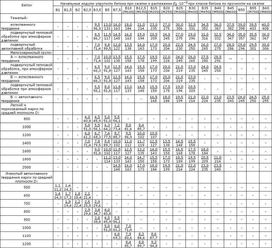
Notes: 1. Above the line shows the values \u200b\u200bin MPa, under the line - in kgf / cm 2.
2. For lightweight, cellular and porous concrete at intermediate values \u200b\u200bof concrete density, the initial moduli of elasticity is taken by linear interpolation.
3. For the cellular concrete of non-autoclave hardening E. B. Take as for autoclave hardening concrete with multiplication by the coefficient of 0.8.
4. For straining concrete value E B. Take as for heavy concrete with multiplication by the coefficient A \u003d 0.56 + 0.006V.
5. The concrete brand shown in brackets do not exactly match the specified classes of concrete.
Table 3. Regulatory values \u200b\u200bof concrete resistance (according to SP 52-101-2003)
Table 4. Calculated values \u200b\u200bof concrete resistance (according to SP 52-101-2003)
Table 4.1. The calculated values \u200b\u200bof the resistance of the concrete compression according to SNiP 2.03.01-84 * (1996)
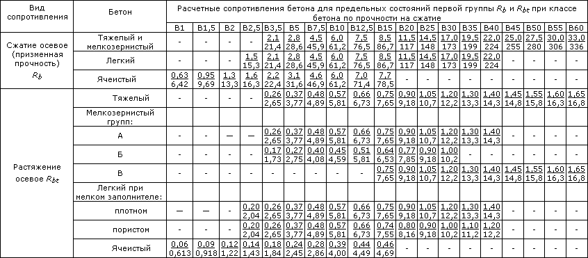
Table 5. Estimated values \u200b\u200bof concrete resistance stretching (according to SP 52-101-2003)
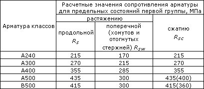
Table 7.1. Estimated resistance for class A reinforcement according to SNiP 2.03.01-84 * (1996)

Table 7.2. Estimated resistance for assembly classes in and k according to SNiP 2.03.01-84 * (1996)

Regulatory data for the calculations of metal structures:
Table 8. Regulatory and calculated resistance when stretching, compression and bending (according to SNiP II-23-81 (1990))
sheet, broadband universal and shaped rental according to GOST 27772-88 for steel structures of buildings and structures

Notes:
1. Through the thickness of the shaped rolled, the shelf thickness should be taken (its minimum thickness is 4 mm).
2. For regulatory resistance, the normative values \u200b\u200bof the yield strength and temporal resistance according to GOST 27772-88 are adopted.
3. The values \u200b\u200bof the calculated resistances are obtained by dividing the regulatory resistance to the reliability coefficients by material, with rounding up to 5 MPa (50 kgf / cm 2).
Table 9. Steel brands replaced by steel according to GOST 27772-88 (according to SNiP II-23-81 (1990))
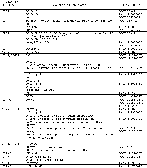
Notes: 1. Steel C345 and C375 Categories 1, 2, 3, 4 according to GOST 27772-88 Replaced steel categories, respectively, 6, 7 and 9, 12, 13 and 15 according to GOST 19281-73 * and GOST 19282-73 *.
2. Steel C345K, C390, C390K, C440, C590, C590K according to GOST 27772-88 Replace the corresponding brands of steel categories 1-15 according to GOST 19281-73 * and GOST 19282-73 *, specified in this table.
3. Replacing steels according to GOST 27772-88 with steel supplied according to other state all-union standards and specifications, not provided.
The calculated resistances for steel used for the production of profiled sheets are given separately.
List Used literature:
1. Snip 2.03.01-84 "Concrete and reinforced concrete structures"
2. SP 52-101-2003
3. Snip II-23-81 (1990) "Steel Constructions"
4. Alexandrov A.V. Strength of materials. Moscow: Higher School. - 2003.
5. Fesik S.P. Handbook on the resistance of materials. Kiev: Budivnik. - 1982.