Maxwell's third equation is a generalization of Gauss's law to the case of variable processes. Gauss's law binds the flow of a vector electrical displacement through an arbitrary closed surface S with a charge Q concentrated inside this surface:
where dS \u003d n0 dS; n0 is the unit vector of the outward normal to the surface S.
Before Maxwell, equation (1.40) was considered only as applied to constant fields. Maxwell suggested that it is also true in the case of variable fields.
The charge Q can be arbitrarily distributed inside the surface S. Therefore, in the general case
where ρ is the volumetric charge density; V- volume bounded by surface S. Bulk charge density
where ΔQ is the charge concentrated in the volume ΔV. Dimension ρ - coulomb per cubic meter (C / m3).
Substituting (1.41) into (1.40), we obtain
![]() . (1.43)
. (1.43)
Equation (1.43) is usually called the third Maxwell's equation in integral form.To pass to the differential form, we transform the left-hand side of this equation according to the Ostrogradskii-Gauss theorem (P. 19). As a result, we get:
![]() .
.
This equality must be true for an arbitrary volume V, which is only possible if
divD \u003d ρ. (1.44)
Relation (1.44) is usually called the third Maxwell's equation. In the Cartesian coordinate system, it is written as
![]() .
.
From equality (1.44) it follows that the divergence of the vector D is nonzero at those points in space where there are free charges. At these points, the lines of vector D have a beginning (source) or end (drain). The lines of vector D start at positive charges and end at negative charges.
Unlike the vector D, the sources (sinks) of the vector E can be both free and bound charges... To show this, we rewrite equation (1.44) for vector E. Substituting relation (1.4) into (1.44), we obtain εоdiv Е \u003d ρ - div P. The second term on the right-hand side of this equality has the meaning of the volume density of charges arising as a result of nonuniform polarization medium (such charges will be called polarizing):
divP \u003d -. (1.45)
Let us explain the appearance of polarization charges on following example... Let there be a polarized medium (Fig. 1.8). Let's mentally select the volume ΔV inside it, limited by the surface ΔS. As a result of polarization in the medium, there is a shift of charges associated with the molecules of the substance. If the volume ΔV is small and the polarization is uneven, then the volume ΔV can enter from one side more chargesthan will come out on the other (in Fig. 1.8, the volume ΔV is shown by the dotted line). We emphasize that polarization charges are "bound" and arise only under the action electric field... The minus sign in formula (1.45) follows from the definition of the vector P (see 1.2.1).

Figure: 1.8. Polarized medium
The lines of the vector P start at negative charges and end in positive. Taking into account formula (1.45), we arrive at the relation εоdiv Е \u003d ρ + ρp, from which the above statement follows that the sources (sinks) of the lines of the vector Е (lines of force of the electric field) are both free and bound charges.
The fourth Maxwell's equation in integral form coincides with Gauss's law for the magnetic field, which can be formulated as follows. The flow of vector B through any closed surface S is equal to zero, i.e.
.(1.46)
 This means that there are no lines of vector B, which only enter the closed surface S (or, conversely, only leave the surface S): they always penetrate it (Fig. 1.9).
Figure: 1.9. Lines of vector B penetrating the surface S
Equation (1.46) is called the fourth Maxwell equation in integral form.The differential form of equation (1.46) can be passed using the Ostrogradsky-Gauss theorem in the same way as it was done in the case of the third Maxwell equation. As a result, we get
divB \u003d 0. (1.47)
Equation (1.47) is Maxwell's fourth equation. It shows that in nature there are no solitary magnetic charges of the same sign. It also follows from this equation that the lines of the vector B ( power lines magnetic field) are continuous.
Maxwell's theory is based on the four equations considered above:
1. The electric field can be both potential ( E Q) and vortex ( E B), therefore, the total field strength E=E Q +E B... Since the circulation of the vector E Q is zero (see (137.3)), and the circulation of the vector E B is determined by expression (137.2), then the circulation of the total field strength vector
This equation shows that not only electric charges, but also time-varying magnetic fields can be sources of an electric field.
2. Generalized vector circulation theorem H (see (138.4)):

This equation shows that magnetic fields can be excited either by moving charges (electric currents) or by alternating electric fields.
3. Gauss's theorem for a field D (see (89.3)):
If the charge is distributed continuously inside a closed surface with a bulk density r, then formula (139.1) will be written in the form
![]()
4. Gauss's theorem for a field IN (see (120.3)):
So, complete system of Maxwell's equations in integral form:
The quantities included in Maxwell's equations are not independent and there is the following relationship between them (isotropic non-ferroelectric and non-ferromagnetic media):
where e 0 and m 0 - electric and magnetic constants, respectively, e and m - the dielectric and magnetic permeability, respectively, g - specific conductivity of the substance.
It follows from Maxwell's equations that the sources of the electric field can be either electric charges or magnetic fields varying in time, and magnetic fields can be excited either by moving electric charges (electric currents) or alternating electric fields. Maxwell's equations are not symmetric about electric and magnetic fields. This is due to the fact that there are electric charges in nature, but there are no magnetic charges.
For stationary fields (E \u003dconst and B \u003dconst ) Maxwell's equations take the form
those. the sources of the electric field in this case are only electric charges, the sources of the magnetic - only conduction currents. In this case, the electric and magnetic fields are independent of each other, which makes it possible to study separately permanent electric and magnetic fields.
Using the Stokes and Gauss theorems known from vector analysis
can be imagined complete system Maxwell's equation in differential form (characterizing the field at each point in space):
If charges and currents are continuously distributed in space, then both forms of Maxwell's equations - integral and differential - are equivalent. However, if there are discontinuity surfaces - surfaces on which the properties of the medium or fields change abruptly, then the integral form of the equations is more general.
Maxwell's equations in differential form assume that all quantities in space and time change continuously. To achieve mathematical equivalence of both forms of Maxwell's equations, the differential form is supplemented boundary conditions, which must be satisfied by the electromagnetic field at the interface between the two media. Integral form Maxwell's equations contains these conditions. They've been covered before:
(the first and last equations correspond to the cases when there are no free charges or conduction currents at the interface).
Maxwell's equations are the most general equations for electric and magnetic fields in resting environments. They play the same role in the theory of electromagnetism as Newton's laws in mechanics. It follows from Maxwell's equations that the alternating magnetic field is always associated with the electric field generated by it, and the alternating electric field is always associated with the magnetic field generated by it, that is, the electric and magnetic fields are inextricably linked with each other - they form a single electromagnetic field.
Bias current or absorption current is a value directly proportional to the rate of change electric induction... This concept is used in classical electrodynamics
Introduced by J.K. Maxwell in the construction of the theory electromagnetic field.
The introduction of the displacement current made it possible to eliminate the contradiction in the Ampere's formula for the circulation of the magnetic field, which, after adding the displacement current there, became consistent and made the last equation, which made it possible to correctly close the system of equations of (classical) electrodynamics.
Strictly speaking, the bias current is not electric shock, but measured in the same units as electric current.
coefficient) is the flux of the vector of the rate of change of the electric field through some surface
![]() (SI)
(SI)
INTRODUCTION TO ELECTRIC EXPLORATION
Study guide for students of advanced training courses in the specialty "Geophysics" under the program "Methods of prospecting and exploration of mineral deposits in field and exploration geophysics"
Kazan 2009
Published by the decision of the Editorial and Publishing Council of Kazan state University them. IN AND. Ulyanov-Lenin "
Approved at a meeting of the Department of Geophysics
Kazan State University,
Minutes No. ____ dated ____ ______________2009
DI. Khasanov
Introduction to Electrical Exploration:manual for self-study for students of advanced training courses in the specialty "Geophysics". - Kazan: Kazan State University, 2009 .-- 75 p.
This training manual is intended for students of advanced training courses in the specialty "Geophysics" under the program "Methods of prospecting and exploration of mineral deposits in field and exploration geophysics." The manual covers the most common issues of electrical exploration. Examples of the use of electrical exploration data for solving various geological problems are given.
© Kazan State
university, 2009
Original Russian Text © D.I. Khasanov, 2009
Introduction
Chapter 1. Theoretical foundations of electrical prospecting ________________________ 4
Chapter 2. Natural electric fields _____________________________8
Chapter 3. Artificial electric fields ___________________________22
Chapter 4. Profiling Techniques ____________________________________30
Chapter 5. Methods of electromagnetic sounding _____________________49
Chapter 6. Electromagnetic properties of rocks _____________________69
Literature __________________________________________________________ 74
Test questions ________________________________________________ 75
Introduction
Electrical prospecting or simply electrical prospecting is a large group of geophysical methods for studying electromagnetic fields of various nature. The purpose of these studies is to determine the electromagnetic characteristics of the geological environment (resistance, conductivity, polarizability, etc.), knowing which you can get valuable information about the structure of the studied area or area. By the type of electromagnetic fields, electrical prospecting can be divided into two sections: the first combines methods that study natural, the second - artificial electromagnetic fields.
Chapter 1. Theoretical foundations of electrical prospecting
Maxwell's equations
The theory of electrical prospecting is based on the system of equations of electrodynamics - Maxwell's equations [Zhdanov, 1986]. These equations for any point in space outside external sources of the field are written in the form:
Here and are the vectors of the strength of the electric and magnetic fields, and are the vectors of the electric and magnetic induction, is the vector of the conduction current density, is the density of electric charges.
Maxwell's equations are supplemented by constraint equations:
where, and are the electromagnetic properties of the medium: electrical conductivity, dielectric and magnetic permeability. Note that the first constraint equation is Ohm's law in differential form.
Physical sense Maxwell's equations
Maxwell's first equation is a differential expression of the total current law, according to which the circulation of the magnetic field in a closed loop is equal to the total current in it. It indicates that the magnetic field is generated by both conduction currents (the first term on the right side of the equation) and displacement currents (the second term). Moreover, conduction currents are the movement of charges, and displacement currents are the rate of change in electrical induction.
The second equation is the differential expression of the law electromagnetic induction, according to which a change in magnetic induction excites a vortex electric field. Thus, an alternating magnetic field generates an alternating electric field, while a constant magnetic field does not create an electric field.
The third equation indicates that in nature magnetic charges does not exist, and the lines of force of the magnetic induction field are closed.
The fourth equation says that electric charges are the sources of the electric induction field. Isolines of the electric induction field start at these charges and are continuous outside them.
TOPIC 4.1. Optics
4.1.1. Propagation theory
electromagnetic waves of Maxwell.
Maxwell's equations
The theory of D.K. Maxwell's theory underlies the explanation of the existence and properties of any electromagnetic waves, such as light waves, radio waves, infrared and ultraviolet radiation. This theory is phenomenological, i.e. it does not consider the molecular structure of the medium and the internal mechanism of the processes occurring in the medium under the influence of electric and magnetic fields. The electrical and magnetic properties of the medium are characterized by the relative permittivity ε, the relative magnetic permeability m and the specific electrical conductivity σ. It is assumed that these parameters of the environment are determined from the experiment.
Maxwell's theory is macroscopic. This means that macroscopic fields of charges and currents are considered, the spatial dimensions of which are immeasurably larger than the dimensions of individual molecules and atoms.
The mathematical expression of Maxwell's theory is a system of four equations, which are written in two forms - differential and integral.
Maxwell's differential equations are obtained from integral ones using two theorems of vector analysis: the Ostrogradsky-Gauss theorem and the Stokes theorem.
Consider ostrogradsky-Gauss theorem.
Let a vector be chosen to characterize any field. Then the vector flux through an arbitrary closed surface S, mentally drawn in this field, is equal to the integral of the vector divergence taken over the volume V bounded by the closed surface S:
The divergence operation on an arbitrary vector is reduced to a spatial derivative of the form:
where a x, a y, a z are the projections of the vector on the axes of a rectangular Cartesian coordinate system.
Consider stokes' theorem.
Let a vector be chosen to characterize any field. Then the circulation of the vector along an arbitrary closed contour L, mentally drawn in this field, is equal to the flux of the vector rot through the surface S, bounded by the closed contour L:
The vector operation rot in Cartesian coordinates is expressed as follows:
Maxwell's first equation
This equation is a generalization of Faraday's law of electromagnetic induction:
However, for an arbitrary contour, the relationship is performed:
Since, in the general case, for a contour that does not change in time, the following relation holds:
Comparing (4.1.5) and (4.1.7) taking into account (4.1.6), for an arbitrary contour L, mentally drawn in an alternating magnetic field, we can write:
The strength of the conduction current can also be represented as:

or, finally:
From the last two equations (4.1.47) it follows that, which indicates the transverseness of the electromagnetic wave. From the first equation (4.1.47) it is clear that the vector H as a result of the vector product must be perpendicular to the plane in which the vectors and lie. Similarly, from the second equation (4.1.47) it follows that the electric field vector must be perpendicular to the plane in which the vectors and lie. Finally it turns out that for any electromagnetic wave the vectors, and make up a triple of orthogonal vectors (Fig. 4.1.1).
4.1.3. Scale of electromagnetic waves
Depending on the frequency ν \u003d ω / 2π or the wavelength in vacuum λ 0 \u003d c / ν, as well as the method of radiation and registration, several types of electromagnetic waves are distinguished:
- radio waves;
- optical radiation;
- x-ray radiation;
- gamma radiation.
Radiwaves are called electromagnetic waves, whose wavelength in vacuum λ 0\u003e 5 10 -5 m (ν< 6·10 12 Гц). Весь диапазон радиоволн принято делить на 9 поддиапазонов (Табл. 4.1.1).
Table 4.1.1
Optical radiation or light are called electromagnetic waves, in which the wavelength in vacuum lies in the range 10 nm\u003e λ 0\u003e 1 mm (the boundaries are conditional). Optical radiation includes infrared, visible and ultraviolet radiation.
Infrared (IR) are called electromagnetic waves emitted by heated bodies, whose wavelength in vacuum lies in the range 1 mm\u003e λ 0\u003e 770 nm.
Visible radiation (light) are called electromagnetic waves whose wavelengths in vacuum lie in the range 770 nm\u003e λ 0\u003e 380 nm. Light is capable of causing visual sensations in the human eye.
Ultraviolet radiation (UV) are called electromagnetic waves whose wavelengths in vacuum lie in the range 380 nm\u003e λ 0\u003e 10 nm.
X-rays (X-rays) are called electromagnetic waves that arise when charged particles and photons interact with atoms of matter. It is characterized by wavelengths in vacuum in the range with conventional boundaries (10-100 nm)\u003e λ 0\u003e (0.01-1 pm).
Gamma radiation (γ rays) called electromagnetic waves with wavelengths in vacuum 0.1 nm\u003e λ 0. This radiation is emitted by excited atomic nuclei during radioactive transformations and nuclear reactions, and also arises during the decay of particles, annihilation of particle-antiparticle pairs and other processes.
4.1.4. Light wave
Light is a complex phenomenon: in some cases it behaves like an electromagnetic wave, in others - like a stream of special particles (photons).
In an electromagnetic wave, the vectors of the electric and magnetic fields oscillate. Experience shows that physiological, photochemical, photoelectric and other actions of light are caused by the presence of oscillations electric vectorwhich is called in this case light vector... Its changes in space and time are given by the plane wave equation:
Here r is the distance measured along the direction of wave propagation.
The ratio of the speed of a light wave in vacuum c to its phase speed v in a certain transparent medium is called the absolute refractive index of this medium:
The refractive index is related to the relative permittivity and permeability by the ratio:
For the overwhelming majority of transparent substances, the value μ ≈ 1. Therefore, we can assume that:
Refractive index values \u200b\u200bcharacterize optical density Wednesday. A medium with a large n will be more optically dense.
The wavelengths of visible light in a vacuum are within:
In matter, the wavelengths will be different. In the case of oscillations with a frequency ν, the wavelength of light in vacuum is:
Using relation (4.1.49), we have the formula for the length of light in matter:
Visible light frequencies are in the range:
The modulus of the time-average energy flux carried by the wave is called light intensity I at a given point in space. The intensity is proportional to the square of the wave amplitude:
| I ∼ A 2 | (4.1.56) |
A light wave, like other electromagnetic waves, is transverse, i.e. the directions of oscillations of the electric and magnetic vectors are perpendicular to the direction of its propagation. In natural light, all directions of oscillation of the electric and magnetic vectors are present. If the wave contains oscillations of the electric vector in only one plane (and the magnetic vector in the perpendicular plane), such a wave is called plane polarized (linearly polarized)... There are also more complex cases of wave polarization - circular and elliptical. In the case of circular polarization, the electric and magnetic vectors rotate in a circle with the frequency of the wave change.
4.1.5. Geometric optics
The lengths of light waves perceived by the eye are very small (∼10 -7 m), therefore, the propagation of visible light in the first approximation can be considered, abstracting from its wave nature and assuming that light propagates along some straight lines called rays. In the limiting case, when the wavelength of light is λ → 0, the laws of optics can be formulated in the language of geometry.
Geometric optics is based on 4 laws:
- the law of rectilinear light propagation;
- the law of independence of light rays;
- the law of light reflection;
- the law of refraction of light.
The law of rectilinear light propagation States that in a homogeneous medium, light propagates in a straight line... This law is approximate: when light passes through very small holes, the dimensions of which are comparable to the length of a wave of light, a deviation from straightness is observed, the greater the smaller the hole.
The law of independence of light rays States that rays when crossing do not disturb each other... This means that the intersection of the rays does not prevent each of them from propagating independently of each other. This law is valid at not too high intensities of light waves.
Geometric optics was based on fermat's principle: light travels along such a path, for which it needs a minimum time.
Let light take time dt \u003d ds / v to pass the ds section, where v is the speed of light at a given point in the medium. Since v \u003d c / n, we get:
Therefore, the time τ required to travel the path from point 1 to point 2 (Fig. 4.1.2) is:

Figure: 4.1.2. To Fermat's principle
The dimension of length
called optical path length... In a homogeneous medium, the optical path length is equal to the product of the geometric path length and the refractive index:
Consequently,
The proportionality of the transit time to the optical path length makes it possible to formulate fermat's principle so: light propagates along such a path, the optical length of which is minimal.
The reversibility of light rays follows from Fermat's principle. Indeed, the optical path, which is minimal when light moves from point 1 to point 2, will also be minimal in the case of light propagation in the opposite direction.
Let us obtain the laws of reflection and refraction of light using Fermat's principle. Let the light fall from point A to point B, reflected from the surface MN (Fig. 4.1.3).

Figure: 4.1.3. Light reflection law as a consequence of Fermat's principle
The direct path from A to B is blocked by a screen E. The medium in which the beam propagates is homogeneous, therefore the minimum optical path length is reduced to the minimum geometric path length. The geometric length of an arbitrarily taken path is equal to AO "B \u003d A" O "B, since the auxiliary point A" is a mirror image of point A, and AO "\u003d A" O ". It can be seen from Fig. 4.1.3 that the ray path has the shortest length , reflected at the point O, for which the angle of reflection is equal to the angle of incidence. When the point O "moves away from the point O, the geometric length of the path increases indefinitely, which contradicts Fermat's principle. This result can be written like this:
The relation (4.1.62) expresses light reflection law: the reflected ray lies in the same plane with the incident ray and the normal reconstructed at the point of incidence; the angle of reflection is equal to the angle of incidence.
Let's find the point at which the ray should be refracted, propagating from A to B, so that the optical path length is minimal (Fig. 4.1.4).
Figure: 4.1.4. Calculating the law of refraction of light from Fermat's principle
For an arbitrary ray, the optical path length is:
To find the minimum value of the optical path length, we differentiate L with respect to x and equate the derivative to zero:
The factors for n 1 and n 2 are, respectively, sinθ and sinθ. "Therefore, we get the relation:
which expresses the law of refraction of light. Using the relationship between the refractive indices and the phase velocities of light propagation in media, we can write the relation (4.1.65) in the form:
Consequently, refraction law reads: the refracted ray lies in the same plane with the incident ray and the normal; the ratio of the sine of the angle of incidence to the sine of the angle of refraction is a constant value for these substances.
In (4.1.66) n 12 is the relative refractive index of the second substance in relation to the first. It is seen from (4.1.65) that when light passes from an optically denser medium to an optically less dense medium, the beam moves away from the normal to the interface between the media. An increase in the angle of incidence is accompanied by a more rapid increase in the angle of refraction, and when a certain limiting angle of incidence is reached, the angle of refraction will be equal to 90 °:
At angles of incidence ranging from θ to 90 °, the refracted wave does not exist, all the energy of the incident wave is converted into the energy of the reflected wave. This phenomenon is called complete internal reflection.
Table 4.1.2
Many optical instruments use glass prisms to refract light. In Fig. 4.1.5 shows the path of a beam of monochromatic light in a prism.

Figure: 4.1.5. Ray path in a prism
After double refraction, the beam turns out to be deflected from the initial position by an angle δ ( deflection angle). The angle θ between the refracting faces is called refractive angle... The angle δ depends on the refractive angle θ and the refractive index of the prism. This dependence can be easily shown for a prism with a small refractive angle θ (thin prism) in the case of a small angle of incidence α. Based on the law of refraction and taking the value of the refractive index of air equal to one, we can write:
At small angles α and θ, the angles α 1, γ and γ 1 are also small. Therefore, instead of (4.1.69), we can write approximately:
From the quadrangle BQDE, in which the angles at B and D are straight lines, we find that the angle BED is 180 ° - θ. Then from the quadrangle BCDE we find:
The angle δ from the triangle BED is:
Substituting the results (4.1.73) and (4.1.70) into (4.1.72), we finally obtain:
4.1.6. Refraction in the lens
In practical applications, the refraction of light at the spherical interface between two media is of great importance. The main part of optical devices - the lens - is usually a glass body, limited on both sides by spherical surfaces. In a particular case, one of the surfaces of the lens can be flat. Such a surface can be considered as spherical with an infinitely large radius of curvature.
Lenses can be made not only of glass, but of any transparent substance with a refractive index exceeding one, for example, quartz, rock salt, plastics and other materials. Lens surfaces can be of more complex shapes - cylindrical, parabolic, etc.
Consider a lens bounded by two spherical refractive surfaces PO 1 Q and PO 2 Q (Fig. 4.1.6).

Figure: 4.1.6. Thin lens
The center of the first refractive surface PO 1 Q lies at point С 1, the center of the second surface PO 2 Q - at point С 2. We will assume that the distance O 1 O 2 is small compared to O 1 C 1 or O 2 C 2. In this case, the points O 1 and O 2 can be considered practically coinciding with the point O - the optical center of the lens. Any straight line passing through the optical center is called optical axis lenses. The one of the axes that passes through the centers of both refractive surfaces is called main optical axis, the rest - side axles.
A beam traveling along an optical axis, passing through a thin lens, does not change its direction. Rays running parallel to the main optical axis, after refraction in the lens, intersect at one point F, located on the main optical axis and called main focus.
Let us show that rays emanating at small angles α from some point A lying on the main optical axis are collected by the lens at one point A1, also located on this optical axis and called image point A (Fig. 4.1.7).

Figure: 4.1.7. Refraction in a thin lens
Let us construct planes tangent to the lens surfaces at points M and N (in the places where the beam hits the lens and exits the lens), and draw the radii R 1 and R 2 of curvature of the lens surfaces at these points. The AMNA 1 beam can then be viewed as a beam refracted in a thin prism with a refractive angle θ. Given the smallness of the angles α, β, α 1, β 1 and the thickness of the lens, we can write:
where a and b are the distances from the light source A and from its image A1 to the optical center of the lens.
From triangles ANA 1 and BEB 1 it follows that:
Taking into account formulas (4.1.75), we get:
It is taken into account that for a thin lens h 1 ≈ h 2 ≈ h. Since, according to the formula () for a thin prism: θ \u003d (n-1) δ, then, using (4.1.77) we have lens formula:
This formula does not include the quantity h, which means that the distance b does not depend on the position of the point M. Therefore, all rays emanating from point A will be collected after refraction by different parts of the lens at one point A 1.
If point A is infinitely far from the lens (a \u003d ∞), i.e. if the rays fall on the lens parallel to the main optical axis, then, according to formula (4.1.78), we have:
The quantity b \u003d f is called focal length of the lens:
Focus lens is called the point at which, after refraction, all rays incident on the lens are collected parallel to the main optical axis.
Taking into account (4.1.80), the lens formula (4.1.78) can now be rewritten as follows:
The reciprocal of the focal length is called lens power:
Optical power is expressed in diopters (dp). 1 dp is the optical power of a lens with a focal length of 1 m.
4.1.7. Huygens principle
In the geometrical optics approximation, the light behind the obstacle should not penetrate into the geometrical shadow region. In fact, the light wave propagates throughout the entire space behind the obstacle, penetrating to penetrate into the region of the geometric shadow, and this penetration will be the more significant, the smaller the size of the hole. When the hole diameter or slit width is comparable to the wavelength, the geometrical optics approximation becomes completely inapplicable.
The behavior of the light behind an obstacle with a hole can be qualitatively explained using huygens principle... According to Huygens' principle, each point reached by the wave motion serves as a center of secondary waves; the envelope of these waves gives the position of the wave front at the next moment in time. Let the wave front parallel to it fall on a flat obstacle with a hole (Fig. 4.1.8).

Figure: 4.1.8. To the Huygens principle
According to Huygens, each point of the wavefront section allocated by the hole serves as the center of secondary waves, which will be spherical in a homogeneous and isotropic medium. Having constructed the envelope of the secondary waves, one can make sure that behind the hole the wave penetrates into the region of the geometric shadow, bending around the edges of the obstacle.
4.1.8. Light wave interference
If several electromagnetic waves propagate simultaneously in a medium, then the waves are simply superimposed on each other, not disturbing one another. This statement, supported by experience, is called the principle of superposition.
In the case when the oscillations of the electric and magnetic vectors in each of the waves occur in such a way that between the corresponding vectors in different waves there is a phase shift constant in time and space, such waves are called coherent... Obviously, the coherence condition can exist only for waves that have the same frequencies and, accordingly, wavelengths.
When coherent waves are added, the phenomenon appears interference, which consists in the fact that electromagnetic waves at some points in space amplify, and at others weaken each other.
Let two waves of the same frequency, propagating in the same direction, excite oscillations at some point in space:
These vectors can be represented as rotating with frequency ω around the common origin of coordinates. Since the phase shift is different, at any moment of time these vectors will take different positions (Fig. 4.1.9).
Figure: 4.1.9. To the calculation of wave interference
Using the cosine theorem, we get the amplitude of the resulting oscillation:
If the phase shift between coherent oscillations is zero (waves are in phase), then the amplitude of the resulting wave is maximum and equal to A \u003d A 1 + A 2. Let the amplitudes of these waves be equal. In this case, we have the amplitude of the resulting wave:
If the phase shift between coherent oscillations is ± π (waves are in antiphase), then the amplitude of the resulting wave is minimal and equal to A \u003d A 1 - A 2. If the amplitudes of these waves are equal, then in this case they cancel each other out:
Coherent light waves can be obtained by dividing, for example, using mirrors, a wave emitted by one source into two. If you force these waves to travel different paths and then superimpose them on top of each other, interference will be observed. Let such a separation occur at the point O (Fig. 4.1.10).

Figure: 4.1.10. Formation of coherent waves
To point P, the first wave will pass in a medium with a refractive index n 1 path S 1, the second wave will pass a path S 2 in a medium with a refractive index n 2. If at point O the phase of the oscillation was equal to ωt, then the first wave will excite oscillation at point P
and the second wave is wobble
then the phase difference turns out to be a multiple of 2π, and the oscillations excited at point P by both waves will occur in phase. Hence, (4.1.93) is the condition for the interference maximum.
If Δ is equal to half an integer number of wavelengths in vacuum:
then the phase difference turns out to be equal to δ \u003d ± (2m + 1) π, and the oscillations excited at point P by both waves will occur in antiphase. Therefore, (4.1.94) is the condition for the interference minimum.
4.1.9. Light wave diffraction
Diffraction is a set of phenomena associated with deviations from the laws of geometric optics. In particular, due to diffraction, light waves go around obstacles and light penetrates into the region of the geometric shadow.
There is no significant physical difference between interference and diffraction.
The light coming from a small bright source through a round hole (Fig. 4.1.11) should, according to the rules of geometric optics, give a sharply limited light circle on a dark background on the screen.

Figure: 4.1.11. Diffraction from a circular hole
Such a picture is observed under ordinary experimental conditions. But if the distance from the hole to the screen is several thousand times larger than the size of the hole, then a more complex picture is formed, which consists of a set of light and dark concentric rings.
An interesting case of diffraction is carried out using a diffraction grating, which is a plate on the surface of which narrow parallel transparent and opaque stripes alternate. The sum of the widths of the transparent and opaque stripes is called the grating period. Let monochromatic light with a wavelength λ be incident on the grating (Fig. 4.1.12). The wave front is parallel to the grating plane.

Figure: 4.1.12. Diffraction grating
The path differences of the rays coming from the corresponding points of the holes, for example, from the right edges (points A, A1, A2, ...), or from the left edges (points B, B 1, B2, ...) have one and the same meaning:
In order for all beams to amplify each other, it is necessary that the path difference be equal to an integer number of wavelengths:
where m is an integer.
This condition makes it possible to determine those values \u200b\u200bof the angles φ and the corresponding directions in which the maximums of light of wavelength λ will be observed.
Several maxima can be observed for a given wavelength. The direction corresponding to m \u003d 0 is φ \u003d 0. This is the direction of the original beam. The corresponding maximum is called the zero-order maximum. For m \u003d 1 we have: sinφ 1 \u003d λ / d, for m \u003d –1 we have: sinφ "1 \u003d –λ / d, ie, there are two first-order maxima located symmetrically on both sides of the zero maximum. maxima of the second, third, etc. orders.
Hence it follows that for waves of different length λ, the positions of the zeroth-order maxima match, and the positions of the maxima of the first, second, etc. orders are different: the larger λ, the larger the corresponding angles.
If white light falls on the grating, a series of color images of the slit are obtained in the plane of the screen. In place of the zero maximum, there will be an image of a slit in white light, and on either side of it, colored stripes will unfold from purple to red.
The larger the overall size of the lattice, i.e. the more strips it contains, the higher its quality: increasing the number of stripes increases the amount of light transmitted by the grating (the maxima become brighter), and improves the resolution of nearby waves (the maxima become sharper).
Knowing the period of the diffraction grating, it can be used to determine the light wavelength by measuring the value of the angle φ, which determines the position of the maximum this order... In this case, we have:
The measurement of the wavelength of light with a diffraction grating is one of the most accurate methods.
4.1.10. Polarization of light waves
Polarized light is called light in which the directions of oscillation of the electric and magnetic vectors are ordered in some way. In natural light, vibrations occur in different directions, quickly and randomly replacing each other.
Distinguish between elliptically polarized light, circularly polarized, plane polarized. In the case of elliptical or circular polarizations, the electric and magnetic vectors rotate in space with a frequency equal to the frequency of the wave, and the ends of these vectors describe either an ellipse or a circle. Rotation can occur both clockwise and counterclockwise. If the vector rotates in space like a right screw, then the polarization is called right, and left - if the vector rotates in space like a left screw.
An important special case is plane polarization. In this case, the electric field vector oscillates in the plane passing through the direction of wave propagation and this vector. This plane is called vibration plane... The magnetic field vector oscillates in a plane that also passes through the direction of wave propagation and this vector, but this plane is polarization plane - makes a right angle with the vibration plane (Fig. 4.1.13).

Figure: 4.1.13. Plane-polarized light wave structure
Plane-polarized light can be obtained from natural light using devices called polarizers... These devices freely pass waves with oscillations, the plane of which coincides with the transmission plane of the polarizer, and detain all other waves.
Let the plane-polarized light of amplitude A 0 and intensity I 0 fall on the polarizer. An oscillation component with amplitude A || will pass through the device. \u003d A 0 cosφ, where the angle φ is the angle between the plane of oscillation of the incident light and the transmission plane of the polarizer (Fig. 4.1.14).

Figure: 4.1.14. Passage of plane-polarized light through a polarizer
Therefore, the intensity of the transmitted light is determined by the expression:
This ratio is called Malus's law.
Let two polarizers stand in the path of the natural ray, the transmission planes of which make an angle φ. From the first polarizer will come out plane-polarized light, the intensity of which I0 will be half the intensity of natural unpolarized light I eat. Using Malus's law, we get:
The maximum intensity is obtained at φ \u003d 0 (the transmission planes of the polarizers are parallel). At φ \u003d 90 °, the intensity is zero - crossed polarizers do not transmit light.
4.1.11. Plane rotation
polarization of light waves
Some substances, called optically active, have the ability to cause rotation of the plane of polarization of plane-polarized light passing through them. These substances include crystals of quartz, cinnabar, etc., some liquids (turpentine, nicotine), solutions of optically active substances in optically inactive solvents (aqueous solutions of sugar, tartaric acid, etc.)
The angle of rotation of the plane of polarization in solids is proportional to the path l traveled by the beam in the crystal:
where α is the optical rotation constant, which is different for different substances.
In solutions, the angle of rotation of the plane of polarization is proportional to the path l traveled by the light in the solution and the concentration from the active substance:
Here [α] is the specific rotation constant.
Depending on the direction of rotation, substances are subdivided into right- and levorotatory. There are right and left quartz, right and left sugar, etc. Molecules or crystals of one modification are a mirror image of molecules or crystals of another modification.
If an optically active substance is placed between two crossed polarizers, the field of view is clarified. To darken it again, one of the polarizers must be rotated by an angle determined by the relations (4.1.99) or (4.11.100). This method can measure the concentration of the active substance in the solution, in particular the concentration of sugar.
§ 22.2. Maxwell's first equation. Maxwell's first equation is written as follows Maxwell's is written as follows: ■
On the right side of it there are two current densities: the conduction current density and the electric current density dD / dt. An electric displacement current occurs in any dielectric, including in. vacuum, when the electric field strength changes over time. Displacement current generates a magnetic field in the same way as conduction current. Although the nature of the conduction current and the displacement current is not the same, they both have the same property - to induce a magnetic field. ![]()
Thus, the meaning of Maxwell's first equation is
is that any change in the electrical displacement in time (dD / dt)
at a certain point of the field (that is, the emergence of a displacement current in it), on the same rights as the conduction current, causes a vortex of the magnetic field (curl H) at this point, that is, causes a vortex magnetic field. If the medium is homogeneous and isotropic, then ε a \u003d const and then
The bias current in the previous sections (especially in Chapters 3 and 8) had to be met more than once. So, it is known that when a capacitor is charged, a current flows through it. This current flows through the dielectric and is the bias current. If, for example, you take an uncharged flat air condenser and connect it to the power source. etc. with. tension U
through resistance R,
then the voltage across the capacitor plates will be 

The displacement current through the surface S is S times greater, i.e., it equal to current conductivity flowing through the conductors connecting the capacitor to the source of electricity. Note that Maxwell's first equation is the total current law in differential form.
Let us make sure that equation (22.1) follows from the law of total current. For this purpose, we take an arbitrary circuit and compose an equation for it according to the law of total current. Total currentpenetrating the area bounded by the contour is equal to the sum of the conduction current and the displacement current. therefore
§ 22.3. Continuity equation. Full current lines
are continuous. Physically, this means that at the boundary between the conducting medium and the dielectric, the conduction current turns into a displacement current.
Can be mathematically formulated principle of continuity
(closedness) of the total current lines.For this purpose, the divergence from the rotor from both sides of (22.1) is identically equal to zero (see § 21.12).
The continuity equation (22.3 ") is also called kept the lawcharge.This law means that electric charge indestructible, it can only move from one place to another. 
§ 22.4. Maxwell's second equation. Maxwell's second equation
are written as follows:
Its physical meaning is that any change in the magnetic
field in time (dB / dt) at any point in the field excites a vortex or
the rotor of the electric field at the same point of the field, i.e., it causes a vortex
electric field
Maxwell's second equation is a differential form of the law of electromagnetic induction.
To verify this, we carry out the following reasoning. Let us mentally take a certain closed loop located in an alternating electromagnetic field. An alternating magnetic flux penetrating the circuit will induce in it. emf
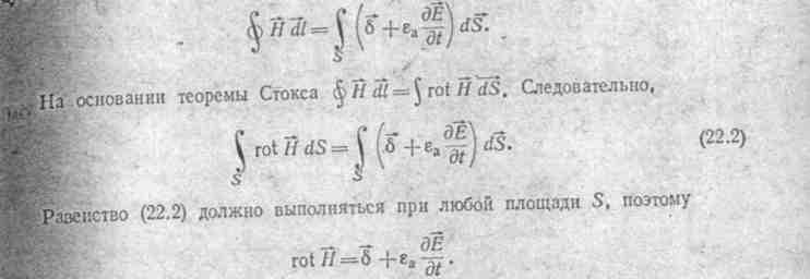
Equality (22.5) must be fulfilled for any areas S, which is possible only if the integrands of both integrals are equal. Consequently, 
rot E \u003d
The minus sign on the right side of the second Maxwell equation (as in the formula
e \u003d- d𝜓 / dt) is explained by the fact that it is based on the right-hand screw rule. If you screw the right screw so that the positive direction of the vector of magnetic induction B at a certain point in space with an increase in induction at this point coincides with the direction of motion of the tip of the screw, then the positive direction: for the vector of electric field strength E when drawing up the circulation of the vector Ealong an infinitely small contour surrounding this point and lying in a plane perpendicular to the vector IN,coincides with the direction of rotation of the screw head.
The minus sign on the right-hand side of (22.4) is set in order to bring into line the actual direction for E under the previously agreed conditions with the direction taken for E as positive.
Both the first and the second Maxwell's equations involve partial (incomplete) derivatives in time. This is explained by the fact that Maxwell's equations are written for such bodies and contours that are stationary with respect to the selected coordinate system.
(Questions of the electrodynamics of moving media are briefly discussed in § 22.9.) 
In an alternating electromagnetic field, in addition to the lines of force of the electric field, "starting" and "ending" on the electric electric charges (as in an electrostatic field), there can also be electric field lines of force that are closed on themselves, covering the lines of force magnetic field (see, for example, fig. 26.5, and).
§
22 5 Maxwell's equations in complex notation... Equations (22 .1)
and (22 4) are recorded for instantaneous values. If H and E change in time sinusoidally, then you can use the symbolic method and write these equations (22.1) and (22 4) in a different form. Let H \u003d H t
sin (ωt
+ 𝜓 n) and E.=E t
sin (ωt
+ 𝜓 E ).
We can write Н \u003d ImH m e iωt
(Im- imaginary part) or, conventionally H
H m e iωt where the complex amplitude H m
\u003d H m e i 𝜓n. In turn EE m e iωt match icon). Since the tension Eand H, besides the fact that they change in the seed according to a sinusoidal law, are vector functions, i.e. vectors oriented in a certain way in space, then an arrow and a point are placed above them: Yo t
and H t .
The arrow means that we are talking about a vector in space, a point - because the projections of this vector on any of the coordinate axes in time change sinusoidally. Then it can be replaced by γ Ee iωt and 
(e iωt as a constant value independent of coordinates can be taken outside the rotor sign). In this case, the first Maxwell equation can be written as


