For simplicity, neglect. Sinusoidal voltage is applied to the chain clamps
u. = U M. × sin Ω. t. .
In the circuit shown in Figure 1, the applied external voltage is balanced in resistance r.called active voltage drop And denotes U. a.
U. a \u003d. I. × r. .
Instant power in the circuit under consideration is equal to the product of instantaneous voltage and current values:
p. = u. × i. .
Figure 3 shows an instantaneous power curve for one. From the drawing it can be seen that the power is not a constant value, it pulses with double.

Figure 3. Instant power curve with active resistance
Average for the period of power value or simply average power is indicated by the letter P. and can be determined by the formula, the proof of which we do not give:
P. = U. × I. × cos. φ ,
where corner φ - angle between tension and current.
Average power is also called active power. This formula is valid for any chains. alternating current.
For a circuit with active resistance, the voltage and current coincide in phase. Therefore corner φ equal to zero, and COS φ \u003d 1. For active power, we get:
P. = U. × I.
P. = I. 2 × r. ,
that is, the power formula for the AC circuit with active resistance is the same as the power formula for the chain direct current. All conductors have active resistance. In the AC circuit, the threads of incandescent lamps, spirals of electric heating devices and risostats, arc lamps, special bifilar windows and straight conductors of small length are possessed by one active resistance.
1 pulsation is called a change in the numerical value of the value under constancy of its sign.
Consider the chain (FIG. 140), consisting of resistance in the influence of inductance and capacity for simplicity neglect.
Sinusoidal voltage is applied to the chain clamps
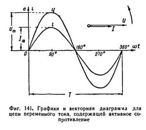
As follows from the last expression, the type of OMA's law for the AC circuit containing resistance, the same as for the DC circuit. In addition, from the Ohm law, the proportionality between the instantaneous voltage value and the instantaneous current value. It follows that in the AC circuit containing the resistance r, the voltage and current are coincided by phase. FIG. 141 There are voltage and current curves and a vector diagram for the chain under consideration, and the length of the vectors denote the active values \u200b\u200band current values. The resistance of the variable current conductors is somewhat more than their constant current resistance. This is explained by the surface effect, the essence of which is set out in 87. Therefore, the resistance of the conductors of the variable current is called active. It is also indicated by the letter R.
In the chain shown in FIG. 140, applied external voltage is balanced by a voltage drop in the resistance R, which is called an active voltage drop and is denoted by u a
Instant power in the circuit under consideration is equal to the product of instantaneous voltage and current values:
|
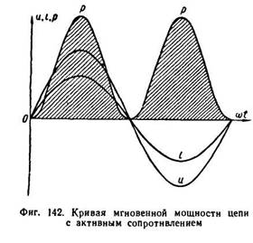
FIG. 142 Dana instantaneous power curve in one period. It can be seen from the drawing that power is not a constant value, it pulses with a double frequency.
The average for the period of the power value or simply the average power is indicated by the letter P and can be determined by the formula, the proof of which we do not give:
Where is the phase shift angle between voltage and current.
The average power is also called an active power. This formula for active power is valid for any AC circuits.
For a circuit with active resistance, the voltage and current coincide in phase. Therefore, the angle is zero, A cos \u003d 1. For active power, we get:
That is, the power formula for the AC circuit with active resistance is the same as the power formula for the DC circuit. All conductors have active resistance. In the AC circuit, the threads of incandescent lamps, spirals of electric heating devices and risostats, arc lamps, special bifilar windows and straight conductors of small length are possessed by one active resistance.
If the alternating current circuit only contains a R (incandescent lamp, an electric heating device, etc.), to which an alternating sinusoidal voltage is applied and (Fig. 1-5, a):
that current i in the chain will be determined by the value of this resistance:
where - the amplitude of the current; At the same time, current I and voltage and coincide in phase. Both of these quantities, as can be seen, can be depicted on the temporary (Fig. 1-5, b) and vector (1-5, c) diagrams. Now install how power changes at any time - instantaneous power characterizing the speed of transformation of electrical energy into other types of energy at the moment
where IU is a product of current current and voltage values.
It follows from the resulting that the power during the period remains positive and pulsates with a twin frequency. Graphically, this can be represented as shown in Figure 1-6. In this case electric Energy It turns into irreversible, for example, in heat, regardless of the current direction in the chain.
In addition to the instantaneous power, the average power is distinguished for the period:
but since the second integral is zero, then you finally have:

![]()
The average for the period of the power of alternating current is called the active power, and the corresponding resistance is active.
The average power and active resistance are associated with irrevocable transformation of electrical energy into other types of energy. Active resistance electrical chain not coming down only to
resistance to conductors in which electrical energy turns into warmth. This concept is significantly wider, since the average power of the electrical circuit is equal to the sum of the capacities of all types of energy obtained from the electrical, on all parts of the chain (heat, mechanical, etc.).
From the obtained ratios it follows that
which is the mathematical record of the Ohm law for the AC circuit with active resistance.

Forced electromagnetic oscillations
Forced electromagnetic oscillations Calculate periodic changes in the current and voltage strength in the electrical circuit occurring under the action of the EDC variable from the external source. An external source of EDC in electrical circuits are alternators operating at power plants.
The principle of the AC generator is easy to show when considering the rotating wire frame in the magnetic field.
In a homogeneous magnetic field with induction in place a rectangular frame formed by conductors (ABSD).
Let the plane of the frame perpendicular to the induction of the magnetic field B and its area equal to S.
The magnetic flow at time t 0 \u003d 0 will be equal to F \u003d B * 8.
With a uniform rotation of the frame around the OO 1 axis with an angular velocity w, the magnetic stream, permerating the frame, will change over time by law:
The change in the magnetic flux excites in the frame of the EDS induction equal to
where E 0 \u003d ASW is the amplitude of the EMF.
If you connect the ends of the frame with an electrical circuit with the help of contact rings and sliding over it, then under the action of EDC induction, changing over time by harmonic law, in the electrical circuit there will be forced harmonic fluctuations in the current strength - alternating current.
In practice, the sinusoidal EMF is excited not by rotating the frame in the magnetic field, but by rotating the magnet or electromagnet (rotor) inside the stator - still windings, piled on cores from magnetic material. In these windings there is a variable EMF, which avoids the removal of the voltage with the help of contact rings.

Alternating current
Consider the processes occurring in the conductor included in the AC circuit.
If the conductor inductance is so small that when it is turned on in an AC circuit, induction fields can be neglected compared to an external electric field, the movement of electrical charges in the conductor is determined by the action only external electric field, whose tension is proportional to the voltage at the ends of the conductor.
When changing the voltage for the harmonic law U \u003d u M COS WT, the electric field strength in the conductor changes along the same law.
Under the action of an alternating electric field in the conductor, an alternating electric current occurs, the frequency and phase of oscillations of which coincides with the frequency and phase of voltage oscillations:
![]()
where i is the instantaneous value of the current, I M is the amplitude value of the current.
The fluctuations in the current in the chains are internally electrical oscillations arising from the action of the applied voltage.
The current amplitude is equal to:
With the coincidence of the phases of fluctuations in the current and voltage force, the instantaneous power of the AC is equal to:
The average value of the cosine square for the period is 0.5. As a result, the average power for the period
![]()
In order for the formula for calculating the power of the AC coincided in a form with a similar formula for DC (P \u003d PR), the concept of current values \u200b\u200bof current and voltage force is introduced. From equality of capacity we get
![]()
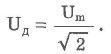
The current value of the current value is called the value, in the root of 2 times the smaller amplitude value:

The active value of the current value is equal to the power of such a direct current at which the average power released in the conductor in the AC circuit is equal to the power highlighted in the same conductor in the DC circuit.
The active value of alternating voltage to the root of 2 times less than its amplitude value:
The average AC power when the phases coincides the fluctuations of the current and voltage force is equal to the product of the current values \u200b\u200bof the current and voltage force:
![]()
Resistance to the element of the electrical circuit in which the transformation of electrical energy into the internal energy is called active resistance. Active resistance of the section of the chain can be defined as the private from the division of the average power per square of the current current value:
The active resistance of R is the physical value equal to the ratio of the power to the square of the current force, which is obtained from the expression for power. At small frequencies, it practically does not depend on the frequency and coincides with the electrical resistance of the conductor.
Suppose that the coil is turned on in the alternating current circuit. Then, when the current change under the law in the coil, EMF of selfinducia occurs. Because electrical resistance The coils are zero, then the EMF is minus the voltage at the ends of the coil created by the external generator (??? what else is the generator ???). Consequently, the change in current causes a change in voltage, but with a phase shift ![]() . The product is an amplitude of oscillations voltage, i.e.
. The product is an amplitude of oscillations voltage, i.e. ![]() . The ratio of the amplitude of voltage fluctuations on the coil to the amplitude of the current oscillations is called inductive resistance
. The ratio of the amplitude of voltage fluctuations on the coil to the amplitude of the current oscillations is called inductive resistance ![]() .
.
Let the condenser be in the chain. With its inclusion, it charges a quarter of the period, then heels as much as the same, but with a change of polarity. When the voltage is changed on the harmonic law condenser ![]() the charge on its plates is equal. Current in the chain occurs when the charge changes:, similarly, the case with the coil of the amplitude of the current force fluctuations is equal to
the charge on its plates is equal. Current in the chain occurs when the charge changes:, similarly, the case with the coil of the amplitude of the current force fluctuations is equal to ![]() . The value equal to the ratio of amplitude to the strength of the current is called capacitive resistance
. The value equal to the ratio of amplitude to the strength of the current is called capacitive resistance ![]() .
.
Active resistance. Current values \u200b\u200bof current and voltage Let us turn to more detailed consideration of the processes that occur in the circuit connected to the source of alternating voltage.
Current strength in the value of the resistor. Let the circuit consists of connecting wires and loads with low inductance and a large resistance R (Fig. 4.10). This magnitude, which we have so far been called electrical resistance or simply resistance, will now be called active resistance.  Resistance R is called active, because in the presence of a load with this resistance, the circuit absorbs the energy coming from the generator. This energy turns into the internal energy of the conductors - they are heated. We assume that the voltage on the clips of the chain is changing according to the harmonic law: u \u003d u m cos t. As in the case of direct current, the instant value of the current force is directly proportional to the instantaneous voltage value. Therefore, to find the instantaneous value of the current strength, you can apply ohm's law: In the conductor with the active resistance of fluctuations in the current force coincide in phase with voltage fluctuations (Fig. 4.11), and the amplitude of the current force is determined by the equality
Power in a chain with a resistor. In the industrial frequency alternating current circuit (V \u003d 50 Hz), the current and voltage change relatively quickly. Therefore, when passing the current on the conductor, for example, on the thread of the light bulb, the amount of highlighted energy will also quickly change over time. But we do not notice these rapid changes.
As a rule, we need to know the average power of the current on the chain area over a large period of time, including many periods. For this, it is sufficient to find an average power in one period. Under the average for the period, the power of alternating current understand the ratio of the total energycoming into the chain for the period to the period.
The power in the DC circuit on the area with the resistance R is determined by the formula P \u003d i 2 R. (4.18) for a very small time interval, the alternating current can be considered almost constant. 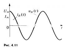 Therefore, instantaneous intensity in the AC circuit on a plot having the active resistance R is determined by the formula P \u003d i 2 R. (4.19) We will find the average power value for the period. To do this, we first transform formula (4.19), substituting the expression (4.16) for the strength of the current and using the known ratio from mathematics
 ![]() The chart of the instantaneous power of time is depicted in Figure 4.12, but. According to the schedule (Fig. 4.12, b.), For the same eighth period, when, the power at any time is greater than. But for the next eighth part of the period when COS 2T< 0, мощность в любой момент времени
меньше чем .
Среднее за период значение cos 2t
равно нулю, а значит равно нулю второе
слагаемое в уравнении (4.20).
Средняя
мощность равна,
таким образом, первому члену в формуле
(4.20):
Current values \u200b\u200bof current andvoltage
.
From formula (4.21) it can be seen that the magnitude is the average for the period of the current value of the current strength:
The chart of the instantaneous power of time is depicted in Figure 4.12, but. According to the schedule (Fig. 4.12, b.), For the same eighth period, when, the power at any time is greater than. But for the next eighth part of the period when COS 2T< 0, мощность в любой момент времени
меньше чем .
Среднее за период значение cos 2t
равно нулю, а значит равно нулю второе
слагаемое в уравнении (4.20).
Средняя
мощность равна,
таким образом, первому члену в формуле
(4.20):
Current values \u200b\u200bof current andvoltage
.
From formula (4.21) it can be seen that the magnitude is the average for the period of the current value of the current strength:  The value equal to the square root from the average value of the current of the current force is called the current value of the force of the non-varying current. Active spectachap of the force of a non-transient current is indicated by I: Actual AC power equal to the power of such a direct current, in which the same number is allocated in the conductor warmAs for alternating current during the same time.
The active value of the alternating voltage is determined similar to the current current value: replacing the amplitude values \u200b\u200bof the current and voltage for the current values \u200b\u200bin formula (4.17), we obtain this oka law for the AC circuit section with a resistor.
As with mechanical oscillations, in the case of electrical oscillations, we usually do not interest us the values \u200b\u200bof the current, voltage and other values \u200b\u200bat each moment of time. Important general characteristics oscillations, such as amplitude, period, frequency, current values \u200b\u200bof current and voltage, average power. It is the acting values \u200b\u200bof current and voltage forces register ammeters and voltmeters alternating current.
In addition, the acting values \u200b\u200bare more convenient than instant values \u200b\u200balso because they are directly determined by the average value of the power of the PC: P \u003d I. 2 R \u003d UI. The fluctuations in the current in the chain with the resistor coincide in phase with voltage fluctuations, and the power is determined by the current values \u200b\u200bof current and voltage.
AC is estimated by its action equivalent to DC validity. Active resistance This resistance of the conductor is called, in which the electrical energy is irreversibly turns into the inner. Let the voltage in the AC circuit varies according to the harmonious law. Under the action of an alternating electric field in the conductor, an alternating current occurs, the frequency and phase of oscillations of which coincides with the frequency and phase of voltage fluctuations. The amplitude value of the current force is equal to the ratio of the amplitude voltage to the conductor resistance. Current power is equal to the product of current and voltage. Then the active resistance can be defined as the ratio of the power of the alternating current on the chain section to the square of the current current. Active value of power The current is called DC strength, due to which the same amount of heat is allocated in the conductor as an alternating current. Find the active value of current value as the ratio of the amplitude value of the current force to a square root of two. The acting voltage value is also in the root of two less than its amplitude value.
When studying forced mechanical oscillations, we got acquainted with the phenomenon resonance. The resonance is observed in the case when the own frequency of the system oscillation coincides with the frequency of changes in external force. If the friction is small, then the amplitude of the established forced oscillations during resonance increases sharply. The coincidence of the type of equations for the description of mechanical and electromagnetic oscillations (allows you to conclude the possibility of resonance also in the electrical circuit if this chain is a oscillatory circuit with a specific vibration frequency.
With mechanical oscillations, the resonance is expressed clearly at small values \u200b\u200bof the coefficient of friction. In the electrical circuit, the role of the friction coefficient performs its active resistance R. After all, it is the presence of this resistance in the chain leads to the transformation of the current energy, but the internal energy of the conductor (the conductor heats up). Therefore, the resonance in the electrical oscillatory con-Lype must be expressed clearly at a small active resistance R.
We already know that if the active resistance is not enough, the own cyclic frequency of oscillations in the circuit is determined by the formula ![]() The strength of the current forced oscillations It should achieve maximum values \u200b\u200bwhen the frequency of alternating voltage applied to the contour is equal to its own oscillating circuit frequency: Resonance in an electric oscillatory circuit The phenomenon of a sharp increase in the amplitude of the forced oscillations of the current strength is called with the coincidence of the frequency of the inlet alternating voltage with the own frequency of the oscillating circuit.
The strength of the current forced oscillations It should achieve maximum values \u200b\u200bwhen the frequency of alternating voltage applied to the contour is equal to its own oscillating circuit frequency: Resonance in an electric oscillatory circuit The phenomenon of a sharp increase in the amplitude of the forced oscillations of the current strength is called with the coincidence of the frequency of the inlet alternating voltage with the own frequency of the oscillating circuit.
The amplitude of the current strength during resonance. As in the case of mechanical resonance, with resonance in the oscillatory circuit, optimal conditions are created for energy flow from an external source in the contour. The power in the circuit is maximum in the case when the current current coincides with the voltage phase. Here there is a complete analogy with mechanical oscillations: with resonance in the mechanical oscillatory system, the outer force (the analog of the voltage in the chain) coincides with the phase at the rate (analogue of the current force).
Not immediately after turning on the external alternating voltage in the circuit, the resonant value of the current is set. The amplitude of the fluctuations of the current force increases gradually - until the energy standing out for the period on the resistor does not compare energycoming into the contour during the same time: 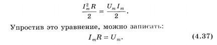 Hence the amplitude of the established fluctuations in the current strength during resonance is determined by the equation
  At R 0, the resonant value of the current of the current is increasingly increasing: (i m) cut. On the contrary, with an increase in R, the maximum value of the current for the current is reduced, and with large Rs to talk about the resonance no longer makes sense. The dependence of the current strength amplitude from the frequency at different resistances (R 1<
R 2 <
R 3)
показана на рисунке 4.19.
At R 0, the resonant value of the current of the current is increasingly increasing: (i m) cut. On the contrary, with an increase in R, the maximum value of the current for the current is reduced, and with large Rs to talk about the resonance no longer makes sense. The dependence of the current strength amplitude from the frequency at different resistances (R 1<
R 2 <
R 3)
показана на рисунке 4.19.
 Simultaneously with the increase in the current for the resonance, the voltage on the condenser and the inductor inductor increase sharply. These voltages with ma.Po active resistance are many times higher than the external voltage.
The use of resonance in radio communications. The phenomenon of electrical resonance is widely used in the implementation of radio communications. Radio waves from various transmitting stations are excited by the variables of various frequencies in the antenna of the radio, as each transmitting radio station operates at its frequency. The antenna inductance is associated with a oscillating circuit (Fig. 4.20). Due to the electromagnetic induction in the contour coil, variables of the corresponding frequencies and forced fluctuations of the current strength of the same frequency occur. But only with the resonance fluctuations in the strength of the current in the circuit and voltage in it will be significant, i.e., from oscillations of various frequencies excited in an antenna, the circuit allocates only those frequencies of which is equal to its own frequency. Setting the circuit to the desired frequency is usually carried out by changing the container condenser. This usually consists of tuning the radio to a specific radio station.  The need to take into account the possibility of resonance in the electrical circuit. In some cases, the resonance in the electrical circuit can bring great harm. If the chain is not designed to work in a resonance, then its occurrence can lead to an accident.
Excessively large currents can overheat wires. Large stresses lead to a breakdown of isolation.
This kind of accident often happened even relatively recently, when the laws of electrical fluctuations were poorly represented and did not know how to correctly count on electrical chains.
With forced electromagnetic oscillations, resonance is possible - a sharp increase in the amplitudes of fluctuations in the current and voltage fluctuations when the frequency of external alternating voltage with its own oscillation frequency is coincided. On the phenomenon of resonance, all radio communication is based.
The study of alternating current circuits with active, capacitive and inductive resistance occurs in the following logical sequence: first the concept of one or another resistance in the AC circuit (comparison with its behavior in the DC circuit), then phase ratios, the formula of the corresponding resistance, conversion Energy in the chain containing only active, capacitive or inductive resistance. The sequence of resistivity in the AC circuit may be somewhat different. The concept of the active value of the current and voltage force can be administered as follows: Initially, an expression is displayed to calculate the instantaneous power values \u200b\u200bon active resistance, from here find the average power value for the period and find out that  There is an average value of the current for the current for the period. Definition: the root square from this value is called the active value of the AC. The name is due to the fact that when the current passes through the area with active resistance, power is distinguished
  The same power is allocated in the DC circuit, the value of which is equal to the active value of the AC. Thus, the active value of the AC is the value of a direct current, which in the resistor R highlights the same amount of heat as an alternating current. It is very important to note that the scales of electrical instruments, for measuring variables with
 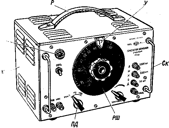 the current and voltage ils are graded in the valid values \u200b\u200bof these values. Consideration of the AC circuit with mixed resistance begins with an experiment - measure the voltage on each of the sequentially turned on the chain elements (lamp, coil and capacitor battery) connected to the voltage source. Pay attention to the following experienced facts: 1. The total voltage is not equal to the amount of stresses in certain areas, as it took place for DC circuits. 2. The voltage on the site comprising the coil and the condenser is not the amount, but the voltage difference on each of them separately. To explain this result can be offered by the students themselves; They know that on inductance, the voltage is ahead of the current on π / 2, and on the electrical capacity behind it on the same magnitude. Since the instantaneous value of the current strength in the chain is everywhere and the same, it is clear that the oscillations of the voltage on inductance and electrical capacity occur with the shift of the phases equal to π, that is, their phases are opposite. 3. Full chain resistance less than the sum of all resistances included in it (active, inductive and capacitive). Students need to be convinced that the smaller the phase shift between the current and voltage, the most part of the power supplying to the chain, is useful, irreversibly turning into other types of energy. Next, we consider the device and the operation of the transformer. On an example of a single-phase transformer, it is shown its action (increase and decrease in voltage) and the device. First, there is no idle mode, and then a loaded transformer. It is advisable to use a retail as a load, since it is easier for them to change the load. Show that with an increase in the load increases with
 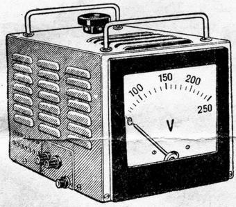 oll current in both secondary and in the primary winding of the transformer. Students offer themselves from the energy positions to explain the increase in current strength in the primary chain (an increase in energy consumption on the load naturally must be accompanied by an increase in energy consumption by primary winding from the generator). For the study of electromagnetic oscillations, the school appliance generator School GZSH is widely used. It overlaps the range of generated frequencies of sinusoidal oscillations from 20 to 20,000 Hz with ranges: "X1" (from 20 to 200 Hz), "X10" (from 200 to 2000 Hz), "X100" (from 2000 to 20,000 Hz) is powered by AC voltage 220 V voltage on the generator's front panel to the network is turned on to the network, the signal light, the subband switch to three fixed positions marked "x1", "x10", "x100", a disk with a non-uniform division scale (from 20 to 200) A variable resistor handle that allows you to change the amplitude of the output signal, the output clamps calculated on the connection of circuits with different resistance (5, 600, 5000 ohms). If the experiments require the frequency of 20-200 Hz, the switch is set to the "x1" position if 200 - 2000 Hz - to the "X10" position, and for frequencies 2000 - 20000 Hz use the "X100" position. Smooth frequency adjustment is carried out by turning the disk. Also widely used PPE-1 and PSU-2 rectifiers
 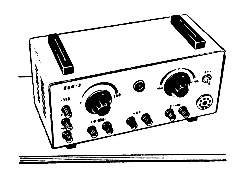 WEUP-2 is designed to provide meals with demonstration installations in electricity experiments. Technical data: The device allows you to get on the output clamps: straightened voltage 350V with maximum power current 220mA; Permanent filtered voltage 250V at maximum load 50mA; adjustable voltage from 0 to 250V DC up to 50mA; adjustable voltage from 0 to + 100V and from 0 to 100V DC to 10mA; Voltage 6.3B of alternating current to 3a. Another power source without which it is almost impossible to exercise many experiments on RNS electricity. School voltage regulator is designed for smooth control of a single-phase alternating current voltage with a frequency of 50 Hz, during laboratory and demonstration experiments in the physical offices of schools. The device joins the network with a shadow cord. The device can be included in the network voltage 127 and 220V. The operating voltage is removed from the clamps indicated "output voltage". In order to properly operate the voltage regulator in the instrument passport, the table of permissible values \u200b\u200bof the electrical load of the regulator load at different stresses supplied to the load, and during network voltages 127 and 220V.
  The voltmeter installed in the voltage regulator has an uneven scale. A reliable count can be held only at 50V. If you need to remove lower voltages from the regulator, you must parallel to the output clamps connect an additional voltmeter with the corresponding measurement limit. The voltage regulator can be used both to increase and lower the voltages of AC, with different demonstration and laboratory experiments, school oscilloscopes of ODS-2 and OES-70 are used for visual display of electromagnetic oscillations. The most widely used oscilloscopes for the study of periodic processes, as well as to study the voltamine characteristics of the diode and triode, hysteresis loops, etc. In the simplest case, the oscilloscope consists of four blocks: the ELT electron-beam tube unit, the generator of the grinding gr, the amplifier of the SC and Block Power supply bp. The main element of the first block is the electron beam tube, on the screen of which the picture of the signal under study is formed (oscillogram). The production of NN is heated by the cathode to, from the surface of which electrons fly out. The electrons flying through the holes of the control electrode focusing the FC cylinder and the anode A, as well as between the plates of the XX and UU, fall on the screen and cause its glow. By changing the potential difference between the cathode and the control electrode, you can change the number of electrons in the beam, and this allows you to adjust the brightness of the image on the screen. The larger the module negative potential On the control electrode relative to the cathode, the less electrons will pass through the control electrode and reaches the anode. The oscilloscope is equipped with a "brightness" knob to control the electron flow in the beam. The electric field between the focusing cylinder and the anode is capable of focusing the consigning electronic bundle. Usually, the network switch is mounted on the front wall, the signal light, the "Login", "input X" and the input divider. The side panel contains electron beam control knobs, "synchronization", "internal. - From the network - external. "," Strengthening ", sweep handles," Ranges 0, 30, 150, 500 Hz, 2, 8, 16 kHz "," Frequency smoothly ", as well as the enhancement handle" Strengthening "," Strengthen X. Oscilloscope ODOS-2 differs from OES-70 constructively and external design. Not only the screen of the electron beam tube is displayed on the front panel, but also the main control knobs. The top row of the handles is designed to control the electron beam: "brightness", "focus", "up-down", "left-right". In the second row from above, the "Strengthening" and voltage divider 1: 1, 1:10, 1:30, 1: 1Oo, 1: 1000, as well as a network switch with a light bulb, are mounted on top. In the third row, the tops are located and the scan generator buttons: "Frequency smoothly", "incl. 1, 2, 3, 4 "," Strengthen X ". The pushbutton switch allows you to change the saw-shaping voltage of the frequency of 20 Hz to 20 kHz. The scan generator works only when the "On" button is pressed. In the lower row, the "Login of", "Input X", "External. Synch ", synchronization buttons" External. "," Internal " and synchronization knob. The OSOS-2 oscilloscope side panel contains a two-channel switch control knobs with two inputs. The switch allows you to observe on the oscilloscope screen simultaneously signals from two alternating current sources. If the frequencies of the sources are the same, then according to the oscillograms obtained, you can judge the phase shift of the filed signals. For example, one input can be submitted a signal proportional to the voltage on the condenser, and on the other, the proportional strength of the current flowing through the capacitor. Then, on the oscilloscope screen, two sinusoids shifted by a phase of 90 ° can be observed. By applying the switch, you can compare the frequency of the test signal with the standard frequency if these signals differ in frequency. On the rear wall of oscilloscopes ODS-2 and OES-70, the sockets are mounted, allowing the signal to be supplied directly to the electron beam plate plates. The ability to feed the test signal directly to the plate allows you to apply the oscilloscope and for DC circuits. Feeding a constant voltage signal on the XX (or UU) plate with a disconnected sweep, you can observe the shift point horizontally (or vertical), and the deviation of this point is proportional to the applied voltage. Consequently, the oscilloscope can be applied as a voltmeter with large internal resistance. To enhance electromagnetic oscillations, low frequency amplifiers are used. Low frequency amplifier - electronic device. Designed to enhance the electrical oscillations of sound frequency from 20 Hz to 20 kHz. Usually, the amplifier consists of several blocks: a pre-amplifier of the voltage, power amplifier, matching the output transformer and power supply. For schools produced amplifiers of different designs and differing in appearance. The ANLC-3 Amplifier of the front panel has a volume knob and a signal light bulb. The knob of the volume control is also produced on and off the network. In the extreme left position of the handle when the device is rotated counterclockwise, the device is disabled. The inclusion is done by turning the handle clockwise after clicking. Since the amplifier is assembled on electronic lamps, he begins to work after their warm-up. Three input jacks are mounted on the side wall: to connect the M - microphone, the adapter, l - lines. The lower socket is connected to the instrument housing. On the back wall there are two pairs of negligence: GR - to connect the loudspeaker (low-voltage output) and l - high-resistance output. There is also an output of a network cord with a fork and an octal panel in which a special fork with a fuse (0.5 A) is inserted for a network with a voltage of 220 V. The plug can be installed in two positions: "220 V" and "127 V". The UNF-5 amplifier is assembled on transistors. On the front of the amplifier, the network switch with the indicator light, the output jack, the input jack for the microphone and the pickup, the microphone connection connector, a low and high frequency adjustment knob, the signal control knob, the overload indicator. On the rear wall there are output of a network cord with a fork and a fuse (0.5 A). Signals can be sent to the amplifier input not only from the microphone and the pickup, but also from other electrical oscillation sensors with voltage from several millivolts to volts (signals from the elements of the AC circuit, sound generator, etc. ). To the output of the amplifier, you can connect not only the loudspeaker, but also other devices: oscilloscope, alternating current measuring instruments, headphones, etc. The power consumption is no more than 40 W, the output is about 5 W. It is forbidden during the operation of the amplifier to change the fuse, disassemble and repair the device included in the network. The amplifier on the vertical panel is included in the set of demonstration devices by radio engineering. The universal enhancer entry clips are mounted on the left. The first lamp operates in voltage gain mode, the second is like a power amplifier. In the anode chain of the second lamp, the coarse transformer is enabled, the secondary winding of which is connected to the clips of a low and high output voltage. Three lower clamps are used to connect the power from the VEU2, the alternating current voltage is 6.3 V for the power of the lamps, and the DC voltage 250 V for the anode chain of the lamps, and on the third bottom of the lamp, is supplied to the two lower clamps. The clamp is given positive potential. Connecting the power supply and assembly of installations with an amplifier on the panel is prohibited to be performed when the PPE-2 rectifier is enabled. In demo installations, preference should be given to the UNG-5 amplifier.


