Power measurement.In chains direct current Power can be measured with an indirect method using an ammeter and voltmeter.
P \u003d UI.,
But the more accurate result gives the measurement of the power of the electrodynamic wattmeter, which is measured with power regardless of the generation. Appearance (a) and wattmeter inclusion scheme (b)showing in Fig.16. The wattmeter has four clamps for connecting mobile and fixed coils into the chain. The fixed coil turns on in the chain sequentially and is called a current coil, and the movable coil together with the added
Fig.16.1. Single-phase wattmeter: but-appearance; b -sham inclusion in electric chain alternating current.
resistance to d - parallel load and is called a voltage coil. The beginning of the coils is marked with an asterisk * I and * U , the end of the current coil is 5 A, and the end of the voltage winding -150v. Since the direction of deviation of the index arrow of the wattmeter depends on the mutual direction of currents in the coils, the conclusions * i and * U are connected to the current source, and the terminals 5 A and 150V-to the load. In view of the fact that the conclusions * i and * u are connected to the same wire, they can be connected to each other by the conductor, which is done in practice when measuring the power in the DC circuit and active power in the variable current circuit.
Measurement of energy.There are the following ways to control the consumption of electricity: 1. An indirect way. In this case, indirect parameters are measured, and the electricity consumption is determined by the calculation. For example, electricity consumption in DC circuits is determined by the formula:
W \u003d u i t(16.1),
where U. - Voltage at the electricity receiver I. - Current in the receiver t.- Time passage.
So To measure the flow of electricity parallel to the receiver, you need to turn on the voltmeter and measure the voltage U., sequentially turn on the ammeter and measure the current strength I. . Time - t. Measured using a chronometer. Removing the testimony from a voltmeter, an ammeter and chronometer of electricity consumption is determined by formula (16.1). In alternating current circuits, electricity consumption is determined by formula (16.2)
W \u003d u i t cosφ(16.2)
So For indirect measurement of electricity flow in this case, in addition to the voltmeter, an ammeter and chronometer, you need to turn on the phazometer to measure the coefficient of Cosφ power.
 2. Immediate way. This method is used in alternating current circuits. In this case, an induction meter is used to measure the electricity consumption. electrical Energy. The counter is a summive device. Its the main difference from the direction of the instrument is that the angle of rotation of its mobile part is not limited to the spring, the counter is increasing and the readings of the counter are summed up. Each turnover of the movable part of the counter corresponds to a certain amount of energy consumed. The counter is turned on in Fig. 16.2 Electric circuit as well as wattmeter (Fig. 16, 1), i.e. Its current winding (3) is switched on sequentially with the load and controls the current strength in the load, and the voltage winding (2) turns on parallel to the load and controls the voltage on the load. Time is controlled by the number of revolutions.
The wattmeter consists of two coils: motionless 1, consisting of a small number of turns of thick wire, and movable 2, consisting of a large number of turns of thin wire. When the wattmeter is turned on, the load current passes through a fixed coil, sequentially included in the chain, and the movable coil is turned on in parallel to the consumer. To reduce the power consumption in parallel winding, the weight of the movable coil is sequentially turned on with an additional resistance of 3 of manganin. As a result of the interaction of magnetic fields of moving and fixed coils, the moment of rotation occurs, proportional to the currents of both coils:

i.e. the torque torque is proportional to the power consumed in the chain.
In order for the instrument's arrow to deviate from zero to the right, you need a current through the coil to skip in a specific direction.
For this, two clamps indicating the start of the windings are designated * and electrically connected. On the wattmeter scale, the rated current and the rated voltage of the device are indicated. For example, if 5 A and 150 V were marked on the scale of the device, the device can measure power up to 750 W. Scale of some wattmeters are graded in divisions. If, for example, a wattmeter at 5 A and 150 V has 150 divisions, then the price of division, or permanent wattmeter, equal to 750: 150 \u003d 5 W / case.
In addition to electrodynamic wattmeters, it is also used to measure the power in the DC circuits, the wattmeters of the ferrodynamic system are also used.
2. Single-phase alternating current. When the electrodynamic wattmeter is turned on into the AC circuit, the magnetic fields are movable and the movable coils, interacting with each other, will cause a rotation of the movable coil. The instant moment of rotation of the mobile number of the instrument is proportional to the product of instantaneous currents of currents in both coils of the device. But due to rapid changes, the mobile system will not be able to follow these changes and the moment of rotation of the device will be proportional to the medium or active power consequently, at the corner of the rotation of the mobile part of the wattmeter, it is possible to judge the value of the active power consumed by the chain.
|

To measure the power of alternating current, the induction system will also be used. FIG. 362 shows the inclusion scheme of the induction wattmeter with a rotating magnetic field. Sequential firmware 1-1, consisting of a small number of turns of thick wire, is located on two opposite pole protrusions and is turned on in series in the chain. Parallel winding 2-2 wattmeters, consisting of a large number of turns of thin wire, is located on two separate pole protractions. Consistently with winding 2-2 turns on inductive resistance 3, which serves for
The angle of the shift is 90 ° between its voltage and current. Thus, with a purely active load, we obtain a shift to an angle of 90 ° between currents in sequential and parallel windings, which is prerequisite creating rotating magnetic field. When the device is turned on, this field, crossing aluminum cylinder 4, induces in it eddy currentswhich, interacting with the field, create a torque acting on the movable part of the device. The angle of rotation of it at any load will be proportional to the active power consumed by the chain:
![]()
The concept of an induction wattmeter with a running field was given in FIG. 335.
When measuring the power wattmeter in low voltage networks with large currents, current transformers are used. To reduce the potential difference between wattmeter windings, the primary and secondary circuit of the current transformer have a common point. The secondary transformer winding is not grounded, as it would mean grounding of one wire wire.
To determine the power of the network P 1 in this case, the reading of the wattmeter P 2 is multiplied by the transformation coefficient of the current transformer:
In high voltage networks, when measuring power, measuring transformers of voltage N current are used (Fig. 363).
For example, if the voltage transformer 6000/100 V and the current transformer 150/5 A, and the wattmeter showed 80 W, the network power will be:
|

When you turn on the wattmeters (meters) through the measuring
Transformers need to attach these devices so that there are currents in their windings in the same direction as if they were directly included in the network.
In addition to the wattmeter, the power of single-phase AC can be determined by the readings of the three devices: an ammeter, a voltmeter and phazometer according to the formula:
![]()
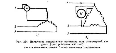
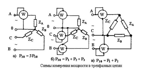
3. Three-phase alternating current. With a uniform load of the three-phase system for measuring the power, one single-phase wattmeter enabled according to the diagram shown in FIG. 364 (A - to connect a star; b - for a triangle connection). According to the serial winding of the wattmeter in this case, the phase current flows, and the parallel winding is turned on to the phase voltage. Therefore, the wattmeter will show the power of one phase. To obtain the power of the three-phase system, you need a single-phase wattmeter reading to multiply by three.
With an uneven load in a four-wire three-phase current network for power measurement, a circuit of three wattmeters is used (Fig. 365). Each single-phase wattmeter measures the power of one phase. To obtain the power of the three-phase system, it is necessary to take the amount of readings of three wattmeters.
With a variable load, it is difficult to obtain a simultaneous count of readings of three wattmeters. In addition, three single-phase wattmeters occupy a lot of space. Therefore, one three-element three-phase wattmeter is often used, which is a connection in one device of three single-phase wattmeters.
|
|

In a three-element electrodynamic wattmeter, three movable parallel coils are attached to one axis associated with the arrow, and the total resulting from the addition of the mechanical effort of each coil will be proportional to the power consumed in three-phase network. In other structures, movable coils located in different places are linked to the flexible ribbons and transmit the total force on the arrow axis.
The active power of the three-phase network during uniform load can be determined
With the help of three devices: an ammeter, voltmeter and phaseometer by the formula:
The power of a three-wire three-phase network with any load (uniform or uneven), regardless of the method of connecting the consumer (star or triangle), can be measured according to the diagram of two wattmeters.
According to the first law of Kirchhoff, the sum of the instantaneous values \u200b\u200bof the currents of all three phases is zero:

The resulting equation shows that one of the wattmeters must be included so that the current of the first phase be thrown over its current coil, and the voltage coil would be under the difference in voltages the first and second phases; Another wattmeter should be included so that the current of the third phase flows through its current coil, and the voltage coil would be under the difference in third and second phases.
Folding the testimony of both wattmeters, we obtain the power of all three phases.
FIG. 366 shows three variants of the circuit of two wattmeters.
From schemes for FUNG. 366 It can be seen that the serial windings of the wattmeters include in any two linear wires of the network. The start of the parallel winding of each wattmeter is connected to the same wire, which includes a sequential winding of the wattmeter. The ends of parallel windings are connected to the third linear wire.
With a uniform active load (\u003d 1), the readings of the wattmeters are equal to each other. With a non-equal unit, the testimony of wattmeters will not be equal. With equal \u003d 0.5, one of the wattmeters will show zero. With less than 0.5, the arrow of this device will begin to deviate left. To get an instrument reading, you need to switch the ends of its sequential or parallel winding.
To measure the active power of the three-phase system according to the testimony of two wattmeters, it is necessary to add their readings or deduct from the reading of one wattmeter, the reading of another wattmeter, which was negative. The power measurement circuit with two wattmeters with the measurement transformers of voltage and current is given in FIG. 367.
It is more convenient to measure power using a three-phase wattmeter, in which two devices included according to the diagram of two wattmeters and acting on one common axis with which the arrow is associated.
|

In high voltage networks, the three-phase wattmeter turns on using measuring voltage and current transformers.
The power consumed by the load in the AC circuit is equal to the average time of the instantaneous voltage values \u200b\u200band the load current. If the voltage and current vary sinusoidally, then the power p can be represented as P \u003d UI Cosφ, where U and I are effective values \u200b\u200bof voltage and current, and φ is the phase angle (shear angle) of the voltage and current sinusoid. If the voltage is expressed in volts, and the current in amperes, the power will be expressed in watts. The Cosφ multiplier, called the power factor, characterizes the degree of synchronization of voltage oscillations and current.
From an economic point of view, the most important electrical value - Energy. The energy W is determined by the capacity of the power during its consumption. In mathematical form it is written as:
If time is measured in seconds, the voltage is in volts, and the current in amperes, the energy W will be expressed in watt-seconds, i.e. Joules. If time is measured in hours, then energy is in Watt-hours. In practice, electricity is more convenient to express in kilowatt clock.
With the help of devices of various systems, measurements of active (), reactive () and complete () power in DC circuits, single-phase and three-phase AC circuits, instantaneous power values, as well as the amount of electricity are widely limited. In this case, the range of measured capacities may be from the share of ICW to dozen GW.
With indirect measurements of power in DC circuits use voltmeter and ammeter method. In this case, devices can be included in two schemes.


Fig. 9.3 Power Measurement Schemes for Voltmeter and Ammeter Indications at Small and Large Load Resistance.
The method is simple, reliable, economical, but has a number of significant flaws:
· The need to take readings on two instruments;
· The need to make calculations;
· Nice accuracy due to the summation of instrument errors.
Compensation method Applied when required high accuracy Power measurements. Using the compensator, the load current and voltage drop on the load are measured. Electrodynamic instruments are used to measure power.

Fig. 9.4 Inclusion scheme for the electrodynamic wattmeter through measuring transformers of current and voltage.
In a wide frequency range apply digital wattmeters. They automatically select measurement limits, self-calibration, have an external interface.
To measure power in three-phase circuits use methods of one, two and three wattmeters.
The first embodiment is used for systems with uniform loads of the phases, the same phase shift angles between the current and voltage. In this case, the load can be enabled according to the star, triangle scheme.

When asymmetric loads use methods of two wattmeters. It is necessary to calculate the total power, taking into account the instrument on the inclusion scheme. When using a three-wattmeters circuit, summation of readings produce to determine the power consumption.
To measure the power in high-frequency circuits, both direct and indirect methods using thermoelectric converters, hall sensors, electronic and digital wattmeters are used. Electromechanical and electronic meters are used to measure energy.
When measuring the power, the phase shift frequency is widely used by the measuring mechanisms of the electrodynamic system, since these devices have a complex functional dependence:
![]() (9.4)
(9.4)
If you pass the current through successively turned on the coils, you can use the current and voltage when you turn on the chain of one of the coils, you can provide an additional phase shift. In this case, you can measure active and reactive power.