Electric networks of 35 kV and below operate with an isolated neutral of the transformer windings or grounding through arc suppression reactors, 110 kV and higher networks - with effective grounding of the neutral of the transformer windings. If it is necessary to compensate for capacitive currents in networks of 6, 10 and 35 kV, arc suppression grounding reactors with smooth or stepwise inductance regulation are installed at the substation. At voltages of 6 and 10 kV, arc suppression reactors are connected to the neutral terminal of a separate transformer connected to the busbars through a switch. The number and capacity of 6-10 kV arc suppression reactors are determined on the basis of the power system data. At a voltage of 35 kV, arc suppression reactors are connected, as a rule, to the zero terminals of the corresponding transformer windings through a fork in the disconnectors, which allows them to be connected to any of the transformers. The consequences of an earth fault, depending on the type of power supply, the values of the capacitive currents and the methods of performing the protections are different. So, in networks with isolated neutral a single-phase earth fault does not cause a short circuit, since a small current flows at the point of the fault, due to the capacitance of the two phases to earth. Significant capacitive currents are compensated by the inclusion of an arc suppression reactor in the neutral of the transformer. As a result of compensation, a small current remains, which is not able to maintain the burning of the arc at the point of fault, therefore the damaged section is not turned off. A single-phase earth fault is accompanied by an increase in the voltage on the undamaged phases to linear, and in the event of a fault through the arc, overvoltages may occur that propagate to the entire electrically connected network. To protect transformers in networks with an insulated neutral or with compensation of capacitive currents from the effects of increased voltages, their neutrals are insulated to the same voltage class as the insulation of line bushings. With this level of insulation, the use of neutral protection means is not required, except for valve arresters connected in parallel with the arc suppression reactor. In networks with effective neutral earthing a single-phase earth fault leads to a short circuit, as can be seen from 2. 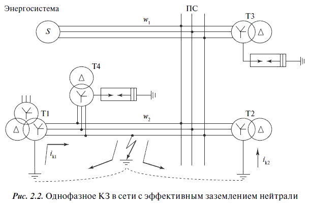 The short-circuit current passes from the fault location along the ground to the grounded neutrals of the transformers T1 and T2, being distributed inversely proportional to the resistances of the branches. Ground fault protection disconnects the damaged area. The single-phase short-circuit current does not pass through the transformers T3 and T4, since their neutrals do not have a solid ground. A single-phase earth fault is the cause of the greatest number of damages in power grids (according to statistics - up to 80% of all short-circuit cases), and it is considered a serious type of damage. Therefore, to prevent it (reduce the possibility of occurrence), special measures are taken, for example, such as partial earthing of the neutrals of transformers. This measure does not apply to autotransformers, since they are designed to work with the obligatory grounding of the ends of the common winding. The number of grounded neutrals in each section is chosen as minimal as possible and should be determined by calculation. The main requirements for the protection of earthed sections are the requirements for relay protection to maintain at a certain level of earth fault currents and to ensure the protection of the insulation of grounded neutrals from overvoltages. The latter requirement is all the more important because all domestic 110–220 kV transformers have a reduced level of neutral insulation. In case of partial-phase disconnections (inclusions) of unloaded transformers with isolated neutral, that is, when the switching equipment (switches, disconnectors or isolators) turns on not three, but two or even one phase, the transient process is accompanied by short-term overvoltages. Reliable protection against such processes is the use of valve arresters. In practice, in addition to the effect of short-term overvoltages, the neutrals of transformers can be affected by the phase voltage of the industrial frequency, which is dangerous both for the insulation of the transformer and for the arrester in its neutral. The danger is aggravated by the fact that such a voltage can remain unnoticed for a long time in case of non-phase switching modes of switches, disconnectors and separators of unloaded transformers, as well as in emergency modes. When an unloaded transformer is switched on half-phase, that is, during phase-by-phase switching, its electrical and magnetic state changes. If the transformer is turned on from the side of the star-connected winding, then in the presence of two phases, the voltage on the neutral and on the disconnected phase will be equal to half the phase. If voltage is applied to one phase, then all the windings of the transformer and its neutral will be energized by the on-phase. In order to avoid negative consequences and prevent an accident, the non-phase mode must be immediately eliminated. Ideally, the best protection measure in such cases is solid grounding of the neutrals of the transformer windings. Therefore, before connecting or disconnecting 110–220 kV transformers from the network, in which the neutral is protected by valve arresters, the neutral of the winding to be switched on or off should be firmly grounded, unless another transformer with earthed neutral... Solid grounding of the neutral of the transformer facilitates the processes of switching off and switching on magnetizing currents, as a result of which the arc burns less intensively when the transformer is disconnected and extinguishes quickly. Disconnection of the earthing switch in the neutral of a transformer operating with an earthed neutral should be carried out immediately after switching on and checking the full-phase connection of the switching device. It is not allowed to leave the neutral grounded for a long time. Grounding the neutral changes the distribution of zero-sequence currents and violates the selectivity of the protection against single-phase ground faults. At present, simplified power supply circuits from single and double passing lines 110-220 kV are widely used. The number of transformers connected to them can reach 4–5. If two or more transformers are connected to such a line, then it is advisable for at least one of them to have a solid neutral grounding, which will allow, in the event of an incomplete-phase voltage supply to the line along with the transformers connected to it, to avoid the appearance dangerous voltages on isolated neutrals of other transformers. A symmetrical three-phase voltage system is formed at the line inputs of all transformers connected to the line, in which the voltage at the isolated neutral of the transformer will be zero. In networks with an effectively grounded neutral, transformers are subject to dangerous overvoltages in the event of emergency modes. This can occur when, when the wire is broken and connected to the ground, a section of the network is allocated that does not have a grounded neutral on the side of the power source. In such a section, the voltage at the neutrals of the transformers becomes equal in magnitude and opposite in the sign of the EMF of the grounded phase, and the voltage of the undamaged phases relative to the ground rises to linear. The overvoltages arising in this case due to the oscillatory overcharge of the phase capacitances to the ground pose a danger to the insulation of transformers and other equipment in this area. In networks with an effectively grounded neutral, in the event of a transition of a part of the network to the operation mode with an isolated neutral, ground fault protection is provided that respond to the zero sequence voltage 3U о, which appears at the terminals of the open triangle of the VT when the phase is connected to ground. Such protections act on the tripping of circuit breakers of transformers with an ungrounded neutral. They are configured so that in the event of a single-phase fault, the insulated neutral transformers are disconnected first, followed by the grounded neutral transformers. At 110 kV substations, where transformers cannot receive feed from MV and LV side, such ground fault protection is not installed and solid grounding of neutrals is not performed. Based on the foregoing, the operating personnel must comply with the following recommendations: when taking out transformers for repair, as well as when changing substation schemes, it is necessary to ensure the neutral grounding mode adopted in the power system, and during switching, in networks with effectively grounded neutral, the allocation of sections without neutral grounding at the supply network of transformers; in order to avoid the automatic allocation of such sections on each substation bus system, where power supply from a network of a different voltage is possible, it is recommended to have a transformer with a grounded neutral with mandatory zero sequence current protection; when a transformer is taken out for repair, the neutral of which is grounded, it is necessary to first ground the neutral of another transformer operating in parallel with it; without changing the position of the neutrals of other transformers, the transformers with an isolated neutral or a neutral protected by a valve arrester are disconnected.
Networks with voltage up to 1 kV in our country, in the overwhelming majority of cases, are performed in the mode of a dead-grounded neutral. This means that the neutral point of the secondary of the transformer in the substation is short-circuited to the grounding device.
Thus, between any phase in the 0.4 kV network and the ground there is always a voltage, called "phase" and having a value of 220 volts. But in some cases, 0.4 kV networks with isolated neutral (IT system) are used.
This can be the case, for example, if the secondary windings of the transformer are connected in a "delta" and there is simply no neutral point. Or, suppose, for some reason, an emergency shutdown of the network associated with a short circuit to ground is unacceptable.
Due to the fact that there is no electrical connection between the mains conductors and the ground in IT networks, a single-phase earth fault can no longer be called "short". However, it cannot be assumed that there will be no leakage current at all with such a short circuit.
The fact is that the insulation of the cores of the supply cable is not an absolute dielectric. The same can be said for all insulators in the network, as well as for other insulating materials.
All of them have some kind of minimum conductivity, so there is always a leakage current through them. And the greater the length of the line, the larger it is. In addition, each core of the supply cable can be represented as one of the capacitor plates.
The second plate is the ground, and the dielectric is the insulation layer and the air layer between the cable and the nearest live parts that are not energized. The capacity of such a capacitor will be the greater, and the resistance of the leakage circuit will be the less, the longer the line is.
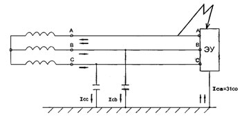
Taking into account the insulation resistance and specific electrical capacity, a network with an isolated neutral can be represented in the form of an equivalent circuit, as shown in the figure. Each phase is connected to ground by means of a parallel connected capacitor and resistor.
Thanks to these elements of the substitution circuit, with a single-phase earth fault in the network, a leakage current occurs along the circuit: "the affected phase - earth - elements of the substitution circuit - good phases". In almost any conditions in networks with an isolated neutral of 0.4 kV, this current is small and can be calculated in milliamperes.
Despite the fact that the current of a single-phase earth fault in networks with an isolated neutral is relatively small, and the network after its occurrence can still work, such a short circuit leads to an emergency mode of operation of the network.
It should be borne in mind that in such networks with a single-phase earth fault, the voltage between the serviceable phases and the ground increases sharply. In fact, this voltage becomes equal to linear - 380 volts. It is fraught with defeat electric shock for electrical and electrotechnical personnel.
And, in addition, a single-phase ground fault in networks with isolated neutral contributes to insulation breakdown and the occurrence of a ground fault in the other two phases.
In fact, there is a possibility of a phase-to-phase short circuit with characteristic overcurrents, for protection against which circuit breakers or fuse-links are required.
At the same time, the small value of the single-phase earth fault current in IT networks becomes the reason that it is simply impossible to determine such a short circuit and turn it off using circuit breakers or fuses - additional relay equipment is needed to signal an alarm.
Thus, IT networks require a larger number of protection and signaling devices, and higher qualification requirements can be imposed on the personnel serving such networks.
OPERATING PRINCIPLE AND OPERATION OF INDUSTRIAL AC AND DC ELECTRIC INSTALLATIONS
Electrical installations is a set of machines, apparatus, lines and auxiliary equipment (together with the structures and rooms in which they are installed) intended for the production, transformation, transformation, transmission, distribution of electrical energy and its transformation into another type of energy ...
The electrical network is a collection of electrical installations serving for transmission and distribution electrical energy, consisting of substations of distribution devices, conductors, overhead and cable power lines. 3-phase electrical installation alternating current industrial frequency 50 Hz is largely determined by the mode of operation of the neutrals of generators or transformers. There are basically two types of central units, insulated neutral and earthed neutral.
Isolated neutral- this is the neutral of the generator or transformer, which is not connected to the grounding device or is connected through devices with high electrical resistance (signaling devices, protection devices, arc extinguishing reactors). A grounded neutral is the neutral of a generator or transformer connected directly to the grounding device or through a small electrical resistance... The level of insulation of electrical installations, the choice of switching equipment, the magnitude of overvoltages and methods of limiting them, the magnitude of the currents of single-phase short circuits to earth (housing), the operating conditions of relay protection, etc., largely depend on the mode of operation of the neutrals.
An earth fault is a random connection of live parts of an electrical installation to structural parts that are not isolated from earth, or directly to earth.
A short circuit to the case is the accidental connection of energized parts of an electrical installation with their structural parts that are normally not energized.
Electrical installations in which the earth fault current (housing) does not exceed 500 A are considered to be electrical installations with low earth fault currents. Electrical installations with a ground fault current (frame) of more than 500 A are considered electrical installations with high ground fault currents.
With low single-phase ground fault currents (033), electrical installations with voltages up to and above 1000 V operate with an isolated generator or transformer neutral. These are 3-phase electrical installations with line voltage 220-380-660 V and 3-35 kV, respectively.
Electrical installations with a grounded neutral (effectively grounded neutral) with a voltage of 110 kV and above operate with large earth-fault currents. 4-wire 3-phase electrical networks with voltages up to 1000 V also work with a grounded neutral, in which the 033 currents may not have large values. These are electrical installations with a voltage of 220/127 V, 380/220 V, 660/380 V.
Single-phase earth faults (housing) account for up to 75% of all types of damage in electrical installations.
The mode of operation of the neutral to a significant extent also affects the electrical safety conditions of people. In electrical installations with insulated and grounded neutral, various electrical protection measures are used, which will be discussed below. Electrical installations, according to the conditions of electrical safety, are divided into electrical installations with voltages up to 1000 V inclusive and above 1000 V.
a) Electrical installations with insulated neutral.
Consider the operation of an electrical network with an isolated generator neutral.
Each wire of the network with an insulated neutral relative to earth has a certain value of insulation resistance, as well as a certain value electrical capacity since each of the wires can be considered as an extended capacitor. On overhead lines, the capacitor plates are the conductor and the ground, and the dielectric is air; on cable lines the conductor of the cable and the metal sheath of the cable, connected to the ground, are the sheaths of the capacitor, and the insulation of the cable cores serves as a dielectric. Insulation resistance is measured in megohms. (1 mOhm = 10 6 Ohm); capacitance is measured in microfarads (1 microfarad = 10 -6 f). This means that during normal operation of an electrical installation, leakage currents flow through the insulation resistance and ground, and currents, called capacitive (I CO), flow through the capacitors to the ground.
In a working electrical network, the geometric sum of the leakage currents and capacitive currents (i.e., taking into account the phase shift in a 3-phase network by 120 °) is equal to zero.
These currents are evenly distributed along the entire length of the wires. In this case, between each phase of the network and the ground, the phase voltage of the network will act (V f = V l: √3).
Leakage currents can be determined by the formula:
I NS = V f : R from
For example, with V l = 380 V and R from = 1 ohm, the leakage current will be:
I NS = 380 (√3∙1∙10 6)
Capacitive currents are determined by the formula:
I with = V f : X c = V f ∙ 2 πfC o ∙10 -6 ( A )
Their value depends on the magnitude of the voltage of the electrical network and the length of overhead and cable lines.
Approximately I can be determined by the following formulas:
Ico= (V∙ e):350 (A) - for overhead lines
Ico= (V∙ e):10 (A) - for cable lines
where V is the line voltage of the network (kv)
e - network length (km)
Under normal network conditions, leakage and capacitive currents are low and do not affect the load on generators or transformers.
When a short circuit of one of the phases to ground occurs, the ground receives the potential of the damaged phase, and there will be a line voltage between the good phases and the ground. Under the action of this line voltage, leakage currents and capacitive currents of two serviceable phases will flow through the fault location and through the ground.
The earth fault current increases by 3 times and, as a rule, has a capacitive character:
I c = 3 I co
If the earth fault is non-metallic, then a so-called intermittent arc may arise at the point of the fault, which periodically extinguishes and ignites at 1 s currents of more than 5-10 A. relative to the ground, reaching values equal to (3-4) V ph of the network, which can lead to insulation breakdown and the occurrence of 2-phase short circuits. The danger of arc overvoltages for insulation increases with an increase in the voltage of the electrical network, therefore the value of earth fault currents 1s is normalized. In networks with a voltage of 6 kV - 1s should not exceed 30 A, in 10 kV networks - not exceed 20 A, in 35 kV networks - not exceed 10 A.
In order to reduce ground fault currents in 3-35 kV networks, compensation of capacitive ground fault currents is used by grounding the neutrals of generators or transformers through special arc suppression coils.
Since the capacitive earth fault current and the inductive current of the arc suppression coil differ in phase by 180 °, they compensate each other at the point of the earth fault. As a result, the earth fault current will not exceed 5-10 A, so that an intermittent arc does not occur.
From the point of view of electrical safety, there is an increased danger to people, because a person touching the uninjured phase and the case is under the influence of line voltage.
With single-phase earth faults, the system of interphase voltages, the stability of the electrical network and consumers are not disturbed, therefore, an immediate disconnection of the power supply lines is not required in order not to create an interruption in the power supply to consumers.
The exception is electrical installations where increased electrical safety conditions are required (electrical installations of peat extraction, coal mines, mobile electrical installations). In these electrical installations, immediate disconnection of currents 033 is used. Relay protection also disconnects synchronous generators and motors with internal short circuits of the stator winding to the case at 1O5-10A due to possible burnout of the stator iron.
V electrical networks with isolated neutral, single-phase faults account for up to 63% of all faults.
PTE of electrical installations of consumers allow the operation of electrical supply networks with a single-phase earth fault for 2 hours with the obligatory finding and disconnection of the damaged supply line.
In networks with isolated neutral, continuous monitoring of the insulation must be carried out.
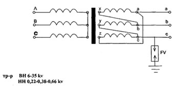
A three-phase electrical network up to 1000 V, which is connected to a network with a voltage above 1000 V through a step-down transformer, must be protected by a breakdown fuse in case of damage to the insulation between the high and low voltage windings. The breakdown fuse is installed on the neutral of the transformer or on the phase of the low voltage winding.
Control over the integrity of breakdown fuses should be provided.
b) Electrical installations with effectively grounded neutral.
In 3-phase electrical installations with a voltage of 110 kV and above, during normal operation, there is a phase voltage of the electrical network between each phase conductor of the network and the ground.
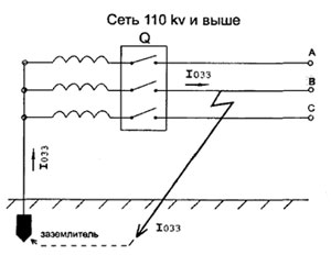
In the event of a short circuit of one of the phases to ground, a short-circuit is formed through the ground and the neutral of the power source, to which the phase voltage of the network is applied.
In this case, currents 033 can reach values of several tens of kiloamperes.
Long-term flow of such currents can cause damage to electrical equipment, therefore, in these electrical installations, they are quickly disconnected by relay protection devices. In this case, overvoltages caused by alternating arcs are also eliminated (which occurs in electrical installations with an isolated neutral. The disadvantage of these electrical installations is the occurrence of an interruption in the power supply to electrical consumers after disconnecting currents 033, as well as the significant cost of the grounding device, which According to the PUE, the swarm should have a very low resistance (R≤0.5 ohm). 3-phase four-wire electrical networks with a solidly grounded neutral voltage up to 1000 V belong to the networks with zeroing, the operation of which is discussed below.
c) Electrical installations direct current.
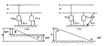
In DC electrical installations with a rated voltage of 110-220-440 V, each of the wires has a certain insulation resistance relative to the ground, distributed along its entire length. In this case, between the "plus" and "minus" pole through the insulation resistance of the wires and the ground is formed electrical circuit and some leakage currents flow.
In normal operation, the leakage currents are negligible.
If the insulation resistance of each of the wires relative to the ground is the same, then each of the wires will have a voltage relative to the ground equal to 0.5 V of the nominal network. With unequal insulation resistances relative to the ground, the voltages are distributed in such a way that their sum will be equal to the V nom of the network.
When one of the wires is shorted to ground between ground and the other working wire, a voltage is generated equal to the full voltage of the network.
This greatly increases the risk of injury to a person when touching an undamaged wire. In this case, the operating mode of the electrical installation is not violated unless a protective shutdown is applied.
In these electrical installations, continuous monitoring of insulation must be carried out. In electrical installations used for electric traction systems, the following values of rated voltages of electrical receivers are adopted:
Urban land transport (tram-wai, trolleybus) - 550 V; subway - 750 V;
main and suburban railways - 3000 V;
industrial electric transport: underground - 250 V; ground -500 V, 1500 V.
On the buses of the supply traction substations, the nominal voltages are taken 10% higher than on the current collectors of the rolling stock.
In traction electrical networks, the contact wire and the contact rail on the metro are the positive pole of the direct current source, which are isolated from the ground using special insulators attached to the metal or reinforced concrete structures of the contact network supports and other structures.
The running rails are the negative pole of the current source. All metal parts of the contact network supports and other structures are grounded on the running rails using special grounding conductors.
In cases of violation of the insulation of the contact network, breakage of the contact network, short-circuiting of opposite-polarity wires, malfunctioning in the rolling stock, etc. short circuits occur. Due to the steady burning of a DC arc during short circuits, burn-out of contact wires can occur, pantographs and other electrical equipment can collapse, fires can occur on rolling stock, which can cause a long break in the movement of rolling stock and a threat to human life.
Therefore, the electric traction system provides for fast, reliable, selective disconnection of currents. short circuit on damaged areas of the contact network using high-speed circuit breakers direct current, having their own shutdown time of the order of 0.04-0.05 sec.
To ensure a clear disconnection of short-circuit currents in the sections of the contact network, conditions must be met under which the short-circuit currents would be greater than the maximum rated load currents of the line and protection installations of high-speed linear switches.
If these conditions are not met, then special technical measures are applied to facilitate reliable disconnection of high-speed switches. This also allows for increased electrical safety of people.
In the electrical networks of Russia, the following are accepted neutral operating modes:
isolated neutral(small capacitive earth fault currents; voltages 6-5-35 kV and 0.4 kV);
compensated neutral(certain excess of capacitive currents; voltage 6 + 35 kV);
effectively grounded (solidly grounded) neutral(large earth fault currents; voltages> 110 kV; 0.4 kV);
high impedance and low impedance neutral grounding(voltage 6, 10 kV).
Abbreviations:
OZZ - Single-phase earth fault
I with sum - total capacitive current
U f max - maximum phase voltage
U f nom - rated phase voltage
Table 1. Isolated neutral mode characteristic
Advantages | disadvantages |
1. Possibility of network operation with SPG for a limited time before taking measures for trouble-free shutdown of the damaged element. 2. No additional equipment and costs for neutral grounding are required. 3. Possibility of self-extinguishing of the arc and self-destruction of a part of the OZZ. 4. Safety of long-term exposure to overvoltages arising in transient modes of OZZ for elements with normal insulation. 5. Simple (in most cases) solution to the problem of protection and selective signaling of stable SPZ. | 1. High probability of occurrence of the most dangerous arc intermittent SPZs. 2. A high probability of secondary insulation breakdowns and the transition of OZZ to double and multiple faults due to overvoltages up to 3.5U f max in arc faults. 3. Significant (several times) increase in the effective value of the current in the place of damage in the case of intermittent arc OZZ due to the free components of the transient process. 4. Possibility of significant damage to electrical machines by current in the place of damage, first of all, with intermittent arc OZZ. 5. Possibility of the occurrence of ferroresonant processes in the network and damage to the heat pump. 6. A high degree of danger to humans and animals located near the site of the SPZ. 7. Limitations on the value of I s sum on the development of the network. 8. High degree of interference on power lines with arc OZZ. |
Table 2. Resonant Neutral Grounding Mode Characteristic (Compensated Neutral)
Advantages | disadvantages |
1. Ability to operate the network with the SPC before taking measures for the trouble-free shutdown of the damaged element. 2. Decrease in current at the place of damage (with resonant GGR tuning, the residual current contains only uncompensated active component and higher harmonics). 3. Significant decrease in the rate of recovery of voltage on the damaged phase after the break of the arc of the current OZZ. 4. High probability (taking into account clauses 2 and 3) self-extinguishing of the arc and self-destruction of most of the OZZ (with limited values of the residual current in the place of damage). 5. The possibility of arcing intermittent OZZ is practically excluded. 6. Reduction of the multiplicity of overvoltages on undamaged phases in comparison with the isolated neutral (up to values of 2.5U fnom at the first breakdown of insulation or arcing intermittent OZZ). 7. Safety of long-term exposure to overvoltages in steady-state and transient modes of OZZ for elements with normal insulation. 8. The possibility of occurrence of ferroresonant processes in the network is excluded. 9. Reducing the influence of arc OZZ on communication lines. | 1. Additional costs for neutral grounding through the GDR and devices for automatic control of the compensation adjustment. 2. Difficulties with the solution of the problem of protection and selective signaling of OZZ. 3. Possibility of occurrence of intermittent arc OZZ, accompanied by overvoltages in undamaged phases up to 2.5 4. Increase in the likelihood of arcing intermittent OZZ and maximum overvoltages in undamaged phases up to (2.6-3) with compensation mismatches. 5. Possibility (taking into account clauses 3 and 4) of secondary breakdowns at network points with weakened insulation. 6. Inability to compensate (without the use of special devices) in the place of damage the active component and higher harmonics. 7. Increase (taking into account clause 6) of the residual current at the place of damage with an increase in the total capacitive current of the network. 8. Restrictions (subject to clause 7) on the development of the network. |
Table 3. High impedance neutral grounding mode characteristics
through a resistor
Advantages | disadvantages |
1. The ability of the network to operate with SPC before taking measures for accident-free shutdown of the damaged element (with limited values of the fault current at the point of damage). 2. Possibility of self-extinguishing of the arc and self-destruction of a part of the OZZ (with limited values of the OZZ current at the place of damage). 3. The possibility of arcing intermittent OZZ is practically excluded. 4. Decrease in the multiplicity of overvoltages on undamaged phases in comparison with the isolated neutral (up to values of 2.5 at the first breakdown of insulation or arc intermittent OZZ). 5. Safety of long-term exposure to overvoltages in transient OZZ modes for elements with normal insulation. 6. The possibility of the occurrence of ferroresonant processes in the network is practically excluded. 7. A simple solution to the problem of protection and signaling of stable SPP. | 2. Increased current at the site of damage. 3. Possibility of occurrence of intermittent arc OZZ, accompanied by overvoltages in undamaged phases up to 2.5. 4. Possibility (subject to item 3) of secondary breakdowns at network points with weakened insulation. 5. Restrictions on the development of the network in terms of I sum. 6. Harder conditions for extinguishing the arc in the place of damage in comparison with networks operating with an isolated neutral or with compensation of the capacitive current OZZ. 7. Large power of the grounding resistor (tens of kilowatts) and problems with ensuring its thermal stability at stable ground protection zones. |
Table 4. Low-impedance neutral grounding mode characteristics
through a resistor
Advantages | disadvantages |
1. The possibility of further development of damage is practically excluded, for example, the transition of the OZZ to a double earth fault or phase-to-phase short circuit (with a quick disconnection of the damaged element). 2. A simple solution to the problem of protection against SPP. 3. The possibility of arcing intermittent SPCs is completely excluded (if the value of the applied active current is sufficient to suppress them). 4. The duration of the impact on the insulation of elements of the network of overvoltages on undamaged phases in transient modes of the OZZ decreases. 5. The possibility of occurrence of ferroresonant processes in the network is excluded. 6. The likelihood of injury to people or animals by the current of OZZ in the place of damage is reduced. | 1. Additional costs for grounding the neutral of the network through a resistor. 2. Impossibility of network operation with SPL. 3. Increase in the number of equipment and line disconnections due to transitions of short-term self-eliminating (with other modes of neutral grounding) insulation breakdowns into complete (completed) breakdowns. 4. Possibility of increasing in some cases the amount of damage to equipment (due to an increase in the current of the OZZ). 5. Possibility of arcing intermittent SPOs in case of insufficient large values superimposed active current. 6. Possibility of secondary breakdowns at points with weakened insulation due to overvoltages on undamaged phases (at the first breakdown of insulation up to 2.5) until the protection of the damaged element is switched on. 7. Increase in the number of disconnections of circuit breakers of network elements. |
At solid grounding of neutral one phase to ground fault is a single-phase short circuit, characterized by a large current. The voltage of the phases in relation to the ground is not higher than the phase nominal; intermittent arcs are excluded. Single-phase short circuits are automatically disconnected. The disconnection leads to interruptions in the power supply to consumers.
Others lack of solid grounding (solidly grounded) neutral is a significant complication and rise in the cost of grounding devices. The latter is due to the fact that for systems with a large earth fault current, PUEs allow a maximum resistance of the grounding loop of 0.5 Ohm, therefore, the number of grounding electrodes must be significant. Due to the significant current of a single-phase short-circuit, which may be greater than the current of a three-phase short-circuit, not all neutrals of the transformers are dullly grounded.


