Under neutral, the neutrals of transformers included in the electrical network of one voltage are meant, that is, having an electrical connection. As we remember, the windings of different voltages of the electric communication transformer do not have each other, and have a magnetic connection, which means that the networks of different stresses are electrically connected with each other. If on the transformers of one network ground (connect from the ground) neutral windings of one voltage (as we remember, in the normal mode of the transformer operation, the voltage to neutral is zero), then the electrical network of this Fig. Three-phase network from isolated neutral: Scheme of capacitive currents with single-phase closure on Earth.
Voltage and will be a network with a grounded neutral. If all the neutral windings of one voltage of transformers of the same network have no connection with the Earth, then these networks are networks with an isolated neutral.
If there will be a closure on the network with an isolated neutral network (single wire) to the ground, then the closed loop will not be, since it is broken in the place of neutral - the land and current of the large value at the point of the closure will not be. There will be no big current, but the current, though small, it will still be a charging or capacitive current of this network. Its value depends on the capacity of this network, which in this case works as a capacitor, the container of which depends on the length of the lines of this network. The network with an isolated neutral is also called the network with a small circuit current to the ground. In the case of single-phase ground-to-ground closure on the network with an isolated neutral neutral shutdown of the equipment on which the closure occurred is not required, since There are no long currents capable of damageing equipment and it can work arbitrarily for a long time without interrupting the power of consumers. Single-phase closure in the network with an isolated neutral is not desirable and it needs to be eliminated in perhaps a shorter period.
1. First, with normal network operation of the network, the voltage of each phase relative to the Earth B (root of 3) times less than the voltage between the phases (the voltage of each phase relative to the Earth is called phase, and the voltage between the phases is linear). When the same phase is closed to the ground, on the other two phases in relation to Earth, the voltage increases to the linear (increases in (root out of 3) times), because The land in this network already has the same potential as the phase closed to the Earth. If at some point of the network on one of the intact phases due to weak, for some reason, its "breakdown" will occur, then a two-phase short circuit (along the contour: Phase - ground closure point - Earth - Pierced insulator - second phase - transformer winding), which is accompanied by large currents damaging equipment. In other words, a single-phase closure on the ground in the network with an isolated neutral is dangerous to the transition to a two-phase short circuit.
2. Second, single-phase ground-to-ground closure on a network with an isolated neutral is a danger to people near the closure point. Since the voltage occurring on the surface of the Earth at the point of contact with the phase decreases sharply by removing from this point (completely disappears at a distance of approximately 8 m), then the person who turned out to be closer to 8 m to the point of the closure falls into the voltage zone.
3. Third, the capacitive current at the ground closure point at a value of more than 5-10 A passes as an electrical arc that when closing inside transformers or generators leads to damage to the winding and magnetic pipeline.
Voltage networks up to 1 kV with isolated neutral are, as a rule, a low-power, it also includes three-way networks with a voltage of 380 and 660 V.
Electrical installations with an isolated neutral should be applied with increased safety requirements (peat developments, coal mines, riding careers, etc. Hazardous production) and subject to reliable network isolation control to quickly detect ground closure. Systems with an isolated neutral, as a rule, do not have the fourth (zero) wire. In such networks, only capacitive currents caused by the voltage and the container of intact phases will be underway in such networks when damaged. The voltage of the damaged phase relative to the Earth will be zero, and the voltage of the two other phases becomes equal to the interphasis voltage. When closed to the Earth, the power supply system with an isolated neutral is not turned off and can operate before finding damage to staff according to PUE to 3 hours.
Differential current relay.
Protective disable device (Sokr. Uzo.; More accurate name: protective shutdown device controlled by differential (residual) current, Sokr. Uzo-D.) or differential current switch (Vitive) or device-disconnecting device (Zoe) - Mechanical switching apparatus or a set of elements that, when reaching (exceeding), the differential current of the specified value under certain operating conditions must cause the contacts. It may consist of various separate elements intended for detection, measurement (comparison with a given value) of differential current and closure and opening of the electrical circuit (disconnector).
The main task of the UZO is the protection of a person from defeat electric shock And on the occurrence of a fire caused by the current leakage through the worn insulation of wires and low-quality compounds.
Combined devices that combine the Uzo and a superflock protection device are also obtained, such devices are called UZO-D with built-in protection from superhowers, or simply diffabtomat. Often, the diffaptatons are supplied with a special indication that allows you to determine for what reason the triggering (from the superflock or on the differential current) occurred.
Scheme of the Uzo and the principle of work
The principle of operation of the UZO is based on measuring the balance of currents between the current-host conductor included in it using a differential current transformer. If the current balance is disrupted, the RCD will immediately open all the contact groups incoming it, thus turning the faulty load.
The RCO measures the algebraic amount of currents flowing according to controlled conductors (two for a single-phase RCD, four for three-phase, etc.): in the normal state of the current, "flowing" by one conductors should be equal to the current, "Executing" on others, that is, the sum of currents passing through the UZO is zero (more precisely, the amount should not exceed the permissible value). If the sum exceeds the permissible value, then this means that part of the current passes in addition to the UDO, that is, controlled electrical circuit Faulty - there is a leakage in it.
Conditions of triggering UDO:
· Direct touch of a person to parts under stress and its contact with "Earth".
· Damage to the main isolation and contact of the current-carrying parts with a grounded housing.
· Replacing zero and grounding conductors.
· Replacing the phase and zero conductors and the touch of a person to parts of it under stress and simultaneously contact with "Earth".
· Open zero conductor Up (and after the Uzo) and the touch of a person to the current or in the tension of parts and its simultaneous contact with the "Earth".
№27. Structural scheme of relay protection.
Fig. Structural scheme of relay protection.
(ICH - measuring part);
(LCH - logical part);
(Uch - reinforcing part);
(IP - power supply)
Each RZ device must detect damage and give the command to disable the power switch. It has three structural parts (Fig. 1.14 ): Measuring reactive), logical (operational), manager (executive). Measuring part (ICH) (Fig. 1.14) carries out continuous control over the state of the protected object and, responding to the appearance of damage (or abnormal mode), it triggers and displays discrete signals to the input of the logical part (LC), which leads it into action.
As controlled values \u200b\u200b(input signals), depending on the type of RZ current or (s), the voltage of the protected object. These values \u200b\u200bin installations with an operating voltage above 1000 V are summarized to the measuring part of protection through the measuring transformers of the current and edge of TV.
Logic part (LCH) perceives the discrete IC signals, produces using logical elements (relay) according to a given program, logic operations and gives output to the RH response to the control part (uch).
Managing (executive) part (Uch) Used to enhance the LC signal to the value required to turn off the switch and actuate other devices, since the LC signals (especially when it is performed on semiconductor elements) usually have insufficient power, and to reproduce the LC signal.
Power supply (IP). To actuate the LCH and accounting elements, feeding the commands to turn off the switches, as well as to power the semiconductor elements Ich and LC, provides a special source of stable voltage.
№28. Types of relay protection devices.
All RZs are divided into basic and reserve . The main is called RD, Providing disconnection of damage within the protected element with the required speed and sensitivity. Reserve are called RD, Reservation of the main RH in the event of its failure or output from work and protect the next section in case of refusal of its RH or switch.
According to the method of ensuring the selectivity of the action of the RZ are divided into two types.
1. There are RZ, the zone of action of which does not go beyond the protected object. They are performed without exposure time and called the RZ with absolute selectivity.
2. The rode group of the RZ acts with the CZ both on the protected element and beyond. Their selectivity is ensured by the selection of time excerpts. Such RZs are called protection with relative selectivity.
According to the principle of action of the measuring bodies that determine the fact of the occurrence of the KZ and the location of its location, the RZ groups respond to the following factors are distinguished: an increase in current, reduce resistance, the appearance of current difference at the ends of the protected area, change the current phases relative to the voltage.
The neutrals of electrical installations are called - general points of winding of generators or transformers connected to the star. The type of communication of neutrals of machinery and transformers with Earth largely determines the level of insulation of electrical installations and selection of switching equipment, overvoltage values \u200b\u200band methods for their limitations, currents with single-phase ground closures, working conditions for relay protection and safety in electrical networks, electromagnetic effect on communication lines and etc.
Depending on the neutral mode electricity of the net divided into four groups:
1) networks with ungrounded (isolated) neutrals;
2) networks with resonant-grounded (compensated
mi) neutrals;
3) networks with efficiently grounded neutrals;
4) networks with deaf-free neutrals.
The first and second groups include networks with a voltage of 3-35 kV, neutral transformers or generators of which are isolated from the ground or grounded through ground reactors.
Networks with efficiently grounded neutrals are applied to voltage above 1 kV. In them, the ground closure factor does not exceed 1.4. The coefficient of closure on the ground is the ratio of the potential difference between the intact phase and land
at the point of closure to the land of the damaged phase to the potential difference between the phase and the ground at this point to the closure. This group includes networks of 110 kV and higher. The fourth group includes networks of 220, 380 and 660 V. The mode of operation of neutral determines the short circuit current. Networks, in which a single-phase closure current on the ground is less than 500 A, is called networks with small closure currents to the Earth (mainly networks with ungrounded and resonant-grounded neutrals).
Currents more than 500 A correspond to networks with large currents to earth closures (these are networks with efficiently grounded neutrals).
In networks with an isolated neutral neutral point of source (generator or transformer) is not attached to the ground contour. IN distribution networks 6-10 kV winding of the supply transformers, as a rule, are connected to the triangle, so the neutral point is physically absent. In installations with an isolated neutral, the process of grounding equipment should not exceed 4 Ohm and with power supply power up to 100 kVA RZ<10 Ом.
In Eu up to 1 kV with an isolated neutral, when closing one phase to the ground, the entire chain is turned off to increase the email. security. Such installations are applied with elevated email requirements. security (mines, metropolitan, peatpooling, mobile installations, some chemical combines).
Advantages:
Lack of need to immediately disable the first single-phase earth closure;
Small current in the place of damage (with low network capacity to the ground).
Disadvantages:
The possibility of arc overvoltages with a mixed character of an arc with a small current (units-dozens of amps) at the site of a single-phase ground-to-ground location;
The possibility of multiple damage (failure of several electric motors, cables) due to insulation breakdowns on other connections associated with arc overvoltages;
The possibility of long-term exposure to the insulation of arc surge, which leads to the accumulation of defects in it and reduce the service life;
The need to perform the insulation of electrical equipment relative to the land on linear voltage;
Complexity of damage location detection;
The danger of electroconducting staff and unauthorized persons with a long existence of ground closure on the network;
The complexity of ensuring the proper operation of relay protection against single-phase closures, since the real current of the earth closure depends on the network operation mode (the number of connections included).
The network with an isolated neutral effectively works only if there is a reliable continuous Insulation Control Devices With the disconnection of the network with an invalid reduction of insulation resistance.
Since ungroundless networks of a small length, as well as compensated networks, can work for a long time with the installation of the phase to the ground, the relay protection against damage to this species is customary to perform with the action to the signal.
The alarm of the earth closure may be non-selective and selective. Non-selective alarm is notified by the service personnel about the occurrence of ground closure without an indication of the attachment on which the insulation disruption occurred. Selective alarm, on the contrary, indicates which attachment caused a closure.
Non-selective alarm, or, otherwise, the insulation control device is based on changing the stresses of wires relative to the Earth. For this purpose, measuring voltage transformers are usually used - three single-phase or one three-phase with a five-track magnetic system. The windings are connected according to the star-star-star-open triangle. The grounding of the zero point of the star of the primary winding of transformers is ensured by measuring the stresses of wires relative to the Earth.

For this purpose, there are three voltmeters included on the secondary phase voltages. The maximum voltage relay is attached to the auxiliary secondary winding connected to the open triangle. The voltage at the outputs of the open triangle is equal to the geometric sum of the secondary three phases relative to the Earth.
In normal mode, the voltmeters show phase voltages, and the voltage on the relay winding is zero. When the wires are closed on the ground on the winding of the relay there is a voltage proportional to the potential of neutral Un(or zero sequence voltage):
![]()
The relay is triggered and starts a warning alarm that attracts the attention of the service personnel to a violation of the normal mode. Insulation control voltmeters, showing wire voltage relative to the Earth, make it possible to determine the damaged wire and roughly estimate the resistance value R.. Since the voltage of the wire relative to the Earth in the entire electrically connected network is the same, then its dimension cannot specify the location of the ground.
Isolated neutral mode Used at a voltage of up to 1 kV only in electrical installations with increased safety requirements (explosive installations, etc.). At voltage of 6 ... 35 kV, this neutral mode is recommended Pue in all electrical installations.
The reason for the wide distribution of the mode of operation with an isolated neutral is that in such a network, the closure of one phase to the ground is not short. The network with an isolated neutral can be operated up to several hours with a phase closure on the ground. The earth closure current turns out many times less than the current of the inter-phase KZ. This is the main advantage of the network with an isolated neutral. In such a network, it is usually not necessary to apply special high-speed protection against land, i.e., additional costs do not require and protect protection.
However, when closed to Earth, such a lack of a network is found as arising overvoltages on damaged phases relative to the Earth.
In fig. 1, and a simplified diagram with an isolated neutral when the phase of the phase A. Inclusion passes the ground of closure on the ground í z.z. It is due to the capacities of the network phases with B, with from relative to the Earth. The value of this current is small and usually does not exceed 100 A.
Fig. 1. Simplified scheme with an isolated neutral when the phase land is closed
In normal mode (Fig. 1, b) phase voltage relative to the Earth is the same and constitute U F \u003d U L / √3, where u l is a linear voltage. When the phase is closed, the Phase A potential becomes zero, i.e., the potential of the Earth (Fig. 1, B). The voltage of the damaged phases B and C relative to the phase A will remain the same as in normal mode, because linear voltages do not change. Thus, the phase voltages in and with relative to the land increase to linear, u 'B \u003d u' c \u003d u l (increase in √3 times), i.e. the fault coefficient on the Earth is √3. At the same time, the possibility of transit of the earth closure into double, which is short circuit and is accompanied by a large current.
In the network with an isolated neutral, the insulation of the phases relative to the Earth is selected by linear voltage so that the network can work for a long time with the ground.
The rules for the technical operation (PTE) of the electric stations and networks of the Russian Federation allow the operation of air and cable lines with a closure to land when the network neutral is isolated until damage is eliminated. At the same time, to find the place of damage should be proceeding immediately and eliminate damage in the shortest possible time due to the danger of lesion by the current of people and animals.
The phase voltages in the network with an isolated neutral during ground closures may exceed linear stresses, which is due to the occurrence of the so-called intermittent electrical arc. The term "interspersed" means that the electric arc is unstable: lights up for a while, then goes out and, after an interval of time, lights up again. Transition processes arising in the electrical circuit of the network (Fig. 1, a) taking into account the intermittent arc leading to the appearance of overvoltages that can reach (3.0 + 3.5) 11, where u is the amplitude of the phase voltage in normal mode. This often leads to a breakdown of isolation, especially electric motors with a voltage above 1 kV.
The presence of overvoltages caused by a mixed electric arc is the main disadvantage of the network with an isolated neutral. This deficiency explains the abundance of proposals for optimizing the neutral regime of urban electrical networks.
The main method of reduced overvoltages during ground closure, according to PTE, is the compensation of the capacitive current of the earth closure, which is achieved using special extinguishing reactors (inductance coils), which include between the neutral network and the earthing. In accordance with PTE, compensation i 3 3 is made if its value is greater than below:
The noncompensated currents in the ground closure can provide unstable burning of the electric arc, i.e., as a result, lead to the appearance of overvoltages. It is especially dangerous to the ground to earth in networks with air lines on reinforced concrete and metal supports, since the current I z. may fail the grounding devices and bearing metal parts of the supports. Therefore, in networks with a voltage of 6-35 kV with air lines on the specified supports, the permissible value of the ground closure current is 10 A.
The current in the place of closure on the Earth is calculated by the approximate formula
where u is a linear voltage, kV; l in - the total length of the network of network lines, km; L K is the total length of the cable lines of the network, km.
Example. Calculate the closure current on the ground in the network with a voltage of 10 square meters. The network contains two air lines with 2 km long and 7 km and 5 cable lines with 1.5 km long; 2.5 km; 0.8 km; 1.2 km; 1.6 km.
Decision:
We determine the total lengths of the air and cable lines L B \u003d 2 + 7 \u003d 9 km; L K \u003d 1.5 + 2.5 + 0.8 + 1.2 + 1.6 \u003d 7.6 km.
Earth closure
Obviously, the compensation of the capacitive current of the earth closure in this network is not required.
Electronic networks can work with grounded or Insulated neutral transformers and generators. Networks 6, 10 and 35 kV operate with an isolated transformer neutral. Networks 660, 380 and 220 V can work with both isolated and grounded neutral. Four-wire 380/220 networks are more prompted, which, in coordination with the requirements of the rules of electrical installation devices (PUE), must have grounded neutral.
Let us see neutral networks. Figure 1, and shows a three-phase current scheme. The winding is depicted connected to the star, but everything uttered below also applies to the case of connecting the secondary winding into the triangle.
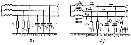
Fig. 1. Scheme of a three-phase current network with an isolated neutral (A). Circuit on the ground in the network with an isolated neutral (b).
It seems to be good as a whole isolation of the current parts of the network from the ground, all the same network conductors always have a connection with the Earth. Communication this dual kind.
1. Isolation of the current-carrying parts has a certain resistance (or conductivity) in relation to Earth, usually expressed in megomas.This means that through the insulation of conductors and the land there is no current of which values. With a good insulation, this current is very small.
Suppose, for example, that between the conductor of one phase of the network and the ground, the voltage is 220 V, and the insulation resistance of this wire measured by a megommeter is 0.5 mΩ. This means that the current on the Earth 220 of this phase is 220 / (0.5 x 1000000) \u003d 0.00044 and either 0.44 mA. This current is called leakage current.
Conditionally for clarity on the insulation resistance diagram of 3 phases R1, R2, R3 is depicted in the form of resistance attached each to one point of the wire. In essence, leakage currents are distributed moderately along the entire length of the wires, in each section of the network they closes through the ground and their sum (geometric, i.e., taking into account the phase shift) is zero.
2. The connection of the second kind appears the capacity of the network of the network in relation to the Earth.How to realize it?
Each conductor of the network and the land can be submitted for itself as two plates of the extended capacitor. In the airlines, the conductor and the earth are like a capacitor, and the air between them is a dielectric. In cable lines of capacitor, cable and iron shell veins, connected to the ground, and the dielectric is insulation.
With alternating voltage, the change in the charges of capacitors causes the appearance and passing through the capacitors of variable currents. These so-called capacitive currents in a serviceable network are moderately distributed along the length of the wires and in each separately taken plot also closes through the ground. In fig. 1, and the resistance of the tanks of 3 phases to the ground x1, x2, x3 is conditionally shown by each to one point of the network. The larger the length of the network, the huge amount of leakage and capacitive currents have a huge amount.
We will see that it will still happen in the figure shown in Figure 1, and the network, if in one of the phases (for example, a) will occur circuit on the ground, i.e. the wire of this phase will be connected to the ground through a relatively small resistance. This case is depicted in Figure 1, b. Since the resistance between the phase A and the ground is not enough, the resistance of the leakage and the tank on the ground of this phase is shunken by the ground-circuit resistance. Now, under the influence of linear voltage of the UB network, leakage currents and capacitive currents of 2-meh phases will be underway through the place of closures and the ground. The passage paths are shown by arrows in the figure.
The closure, shown in Figure 1, B, is referred to as a single-phase closure on the ground, and the emergency current occurring with all this - single-phase closure.
Imagine now that one-name closure due to damage to the insulation came out not specifically to the ground, but on the body of any electrical receiving - an electric motor, an electronic apparatus, or on the iron structure, on which the electronic wires are laid (Fig. 2). Such a closure is called circuit on the body. If with all this housing of the electrical receiving or the design does not have the connection with the Earth, then they receive the phase potential of the network or close to it.
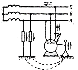
Fig. 2.
Touching the housing is tantamount to the phase. Through the human body, its shoes, the floor, earth, leakage resistance and capacitive resistance of good phases appear a closed circuit (for simplicity in Fig. 2 capacitive resistance not shown).
The current in this circuit circuit is depending on its resistance and can cause a severe defeat or to be fatal for him.
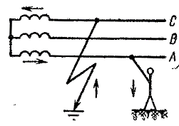
Fig. 3. Touching a person to the conductor on the network with an isolated neutral if there is a closure on the ground
From the pronounced it follows that to pass the current through the Earth, the presence of a closed chain is needed (from time to time they represent that the current "goes into the ground" is erroneously). In networks with an isolated neutral voltage up to 1000 V leakage currents and capacitive currents are usually small. They depend on the state of isolation and the length of the network. Even in a branched network, they are within the boundaries of several amps and below. Because these currents are usually insufficient to melt the fused inserts or disabling the circuit breakers.
At stresses above 1000, capacitive currents are basically significant, they are able to reach several 10 amps (if their compensation is not provided). But in these networks, it is not usually not used to disable the victims of the bobbed sections with single-phase closures, so as not to create interruptions in power supply.
So Makar, in a network with an isolated neutral, if there is a single-phase closure (what the insulation control devices are indicated), electrical receivers continue to work.This may be, because with single-name closures, the linear (interpasic) voltage does not change and all electrical receivers are uninterrupted. But with any single-phase closure on a network with an isolated stress neutral, the non-injected phases are growing to the linear, and this contributes to the emergence of the second ground-circuit in another phase. The dual circuit on the ground makes a harsh danger for people. It does not matter what the network with the presence of single-phase closure in it should be treated as in emergency conditionbecause the overall safety conditions in this state of the network deteriorate sharply.
Thus, the presence of "land" increases the risk of lesion by electron current when touched into parts under voltage. This can be seen, for example, from Figure 3, where the passage of the lesion current is shown in a random touch of the phase A and unreasonable "land" in the Phase C. Man with all this turns out to be under the influence of linear network voltage. Because single-phase closures on Earth or the body must be eliminated as soon as possible.