Before finally proceed to the settlement part of the ground, a few more excerpts from Pue 1.7:
1.7.15. The earthing is a conductive part or a set of interconnected conductive parts in electrical contact with the ground directly or through an intermediate conductive medium.
1.7.16. Artificial earthing - a grounding agent specifically performed for grounding purposes.
1.7.17. Natural earthing - third-party conductive part in electrical contact with the ground directly or through an intermediate conductive medium used for grounding purposes.
1.7.18. The grounding conductor is a conductor connecting the grounded part (point) with a grounding.
1.7.19. The grounding device is a set of earthing and grounding conductors.
1.7.20. Zero potential zone (relative land) - part of the land outside the zone of the influence of any earthing man, electric potential which is taken equal to zero.
1.7.21. The zone of spreading (local land) is the land zone between the earthing and the zero potential zone.
The term land used in the chapter should be understood as land in the zone of spreading.
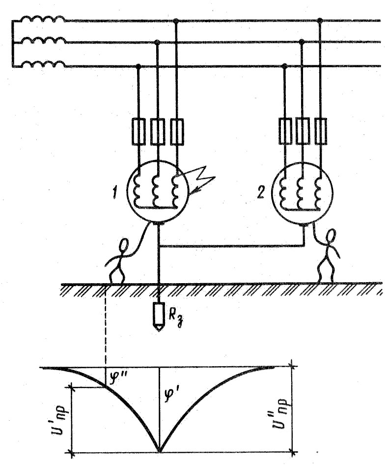
We decipher some terms about what is said above, if you skip the current through the ground, then on the ground itself and at the points of the Earth, located in the immediate vicinity of it, the potentials (relatively infinitely remote point) will occur, the distribution of which is shown in Fig. 1. From the figure it is clear that with the removal of the grounding the grounding the ground, the potential is reduced, since the cross section of the earth through which the current flows is increasing. In remote points, the potentials are close to zero. Thus, the points of the zero potential can serve as the points that are quite remote from the earthing, the potentials of which are almost equal to zero. Usually a distance of several tens of meters. The steepness of the potential distribution curve depends on the conductivity of the soil: the greater the conductivity of the soil, the more common form is the curve, the farther the points of zero potential are located.
Resistance that has a soil current is called
resistance to spreading.
In practice, the resistance to spreading is not related to the soil, but to the grounding and apply a reduced conditional term " ground resistance».
Ground resistance  (RSM.) is determined by the ratio ratio ( UZM) on the earthing relative to the point of zero potential to the current ( IZM.) flowing through the earthing, so the main calculation protective grounding It comes down to determining the resistance of the grounding current. This resistance depends on the size and number of grounding conductors, the distances between them, the depths of their attachment and conductivity of the soil.
Selection of the grounding scheme:
In a row or contour (Single grounding Consider later, see ) It is produced to determine the resistance of the grounding constructed during operation, its size, shape and calculation part. A number or circuit of grounding consists of vertical earthing, horizontal earthing and grounding conductor. Vertical earthingers are plugged into the soil at a certain depth.
Horizontal earthing people connect vertical grounding. The grounding conductor connects the ground contour directly with the electrical wheel.
Dimensions and number of these earthing, the distance between them, the resistivity of the soil - all these parameters are directly dependent on the ground resistance to calculate. Below in the diagram. 2, show the most common vertical artificial entrancers (electrodes) - triangle, in a row and by the ground contour:
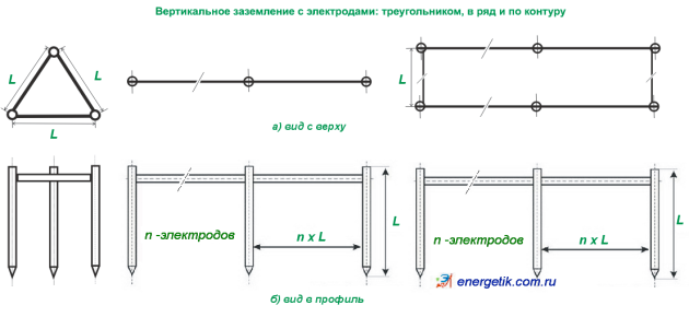
Fig. 2.

Fig. 3.
In fig. 3 shows the standard diagram of the longitudinal section of the vertical earthing to calculate the electrode of a single, triangular, in a row or contour grounding, where t (m) - in the general case, the depth of the trench is allowed 0.5 -0.8 m., The length of the electrode rod (L) is recommended 1.5 - 3 m. where H is the thickness of the top layer of the soil, if the ground is inhomogeneous, It is necessary to carry out calculations ρ eq. for two-layer soil.Formulas for grounding:
The main calculation of the protective ground is reduced to the determination of the resistance of the earthing current spreading. This resistance depends on the size and number of grounding conductors, the distances between them, the depths of their attachment and conductivity of the soil.
The purpose of calculating the ground is to determine the number of grounding rods and the length of the strip that connects them.
To transfer the round metal (bar, pipe) in the strip: B \u003d 2 · D, where b is the width of the strip M m., D is the diameter of the bar, pipes in m. And, accordingly, on the turnover, the band in the diameter: d \u003d 0.5 · B; To transfer the corner to the diameter: d \u003d 0.95 · b, where b is the width of the shelf angle in m.
1. The distances between the grounding rods are taken from the ratio of their length (see Fig. 2), that is:
a \u003d 1xl; a \u003d 2xl; a \u003d 3xl
where, a. - distances between grounding; L. - Rod length (electrode), 1 - 3 ratio.
2. Resistance to spreading the current of one vertical earthing (rod):

Where, ρ eq. - Equivalent soil resistivity by calculating the formula: ρ eq \u003d ψ · ρ, ψ - raising climatic zone coefficient, ρ — specific resistivity Ohm · m; L - Length of the rod, m; d - its diameter, m; T. - distance from the surface of the Earth to the middle of the rod, m. (See Fig. 3, h 1 \u003d 0,5L + T), H - The thickness of the upper layer of soil with inhomogeneous soil (two-layer). Below in fig. 4 Formulas and arrangements of electrodes for calculating logarithms:
![]()
Fig. four (approx. where H 1 \u003d T)
3. In an inhomogeneous soil (two-layer), the equivalent resistivity of the soil is located by the formula:
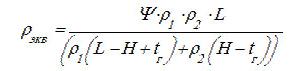
where - Ψ - seasonal climatic coefficient (Table 5); ρ 1, ρ 2 - the resistivity of the upper and lower layer of the soil, respectively, ohm · m (see Table 5); N - thickness of the upper layer of soil, m; T - Blooming the vertical earthing (the depth of the trench) T \u003d 0.5 - 0.8 m.
4. The number of necessary earthingers is determined by the formulas:
4.1 by the method of approximation (how to use this method, we will tell you in the examples later):
![]()
where, k is the ratio of the distance between grounding rods (see paragraph 1), R 1 \u003d R 0 - (see clause 2), R holes - regulatory requirements of resistance (Pue 1.7.101. or 1.7.103. See page ).
4.2 Using tables (excluding horizontal ground resistance):
 where, ψ - the seasonality coefficient of the vertical earthing (see table 6, page
); R H is the normalized resistance to spreading the current of the grounding device, see Table 8, below):
where, ψ - the seasonality coefficient of the vertical earthing (see table 6, page
); R H is the normalized resistance to spreading the current of the grounding device, see Table 8, below):
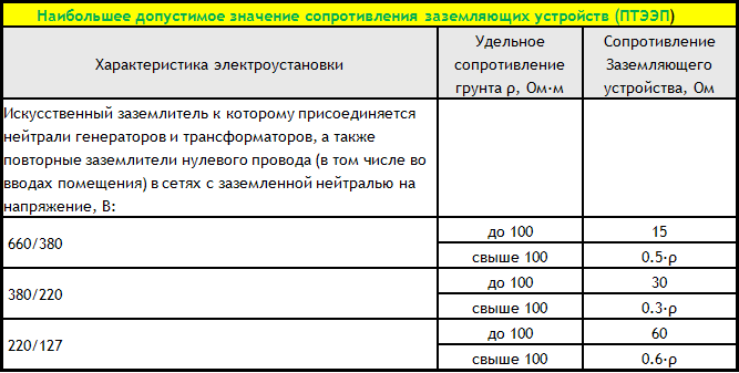
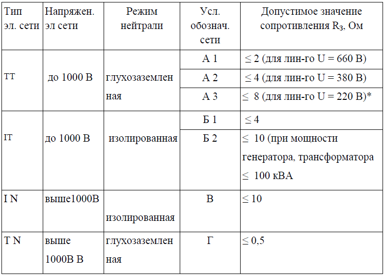 Table 8.
Posted 30.11.2011 (relevant until November 30, 2012)
The calculation of grounding devices is mainly due to the calculation of the earthing actor actor, since grounding conductors are in most cases under the conditions of mechanical strength and resistance to corrosion in PTE and PUE. Exception is only installation with a remote grounding device. In these cases, consistently integrated connecting line resistance and the earthing is calculated so that their total resistance is not exceeded.
The issues of calculating grounding devices for the Polar and Northeastern regions of our country should be especially allocated. For them, multidimensional soils are characterized, having a specific resistance of surface layers per one - two orders of magnitude higher than under normal conditions of the middle band of the USSR.
The calculation of the resistance of the entrancers in other areas of the USSR is performed in the following order:
1. The permissible resistance of the grounding device R zm is installed. If the grounding device is common to multiple electrical installations, the calculated impedance of the grounding device is the smallest of the required.
2. Determined by the required resistance artificial earthing Taking into account the use of natural grounds included in parallel, from expressions
![]() (8-14)
(8-14)
where r zm - Double resistance grounding device according to p. 1, r and resistance of the artificial earthing; R E-resistance of a natural earthing. The calculated specific resistance of the soil is determined, taking into account the increase in the coefficients that take into account the drying of the soil in the summer and the freezing of winter.
In the absence of accurate soil data, you can use the table. 8-1, where the average data on the resistance of the soils recommended for preliminary calculations is given.
Table 8-1
Middle resistances of soils and water recommended for preliminary calculations
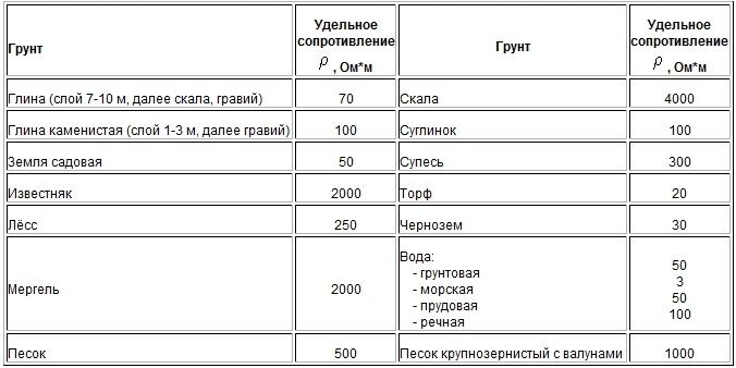
Note. The specific resistances of soils are determined at a humidity of 10-20% by ground ground
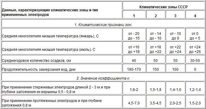
Measuring the resistivity to obtain more reliable results produced in the warm season (May - October) in the middle lane of the USSR. To the measured value of the resistivity of the soil, depending on the state of the soil and on the amount of precipitation, correction coefficients K, taking into account the change due to drying and freezing of the soil, i.e. p q \u003d Р
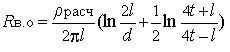
4. The resistance to spreading one vertical electrode R.O. Formulas tab. 8-3. These formulas are given for rod electrodes from round steel or pipes.
When applying vertical electrodes from angular steel in the formula instead of the pipe diameter, an equivalent corner diameter calculated by expression is substituted
![]() (8-15)
(8-15)
where b is the width of the sides of the corner.
5. The approximate number of vertical entries is determined at a previously accepted utility factor.
![]() (8-16)
(8-16)
where R V.O. - resistance to spreading one vertical electrode, defined in clause 4; R and - the necessary resistance of the artificial entrance; K and, B, ZM - the utilization coefficient of vertical entrancers.
Table 8-2.
The value of the boost coefficient K for various climatic zones
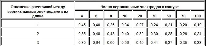
The coefficients of using vertical entries are given in Table. 8-4 when they are located in a row and in Table. 8-5 when placing them along the contour
6. The resistance to spreading the horizontal electrodes RG by the formulas of the table is determined. 8-3. The coefficients of using horizontal electrodes for the previously accepted number of vertical electrodes are taken in Table. 8-6 at the location of the vertical electrodes in a row and in Table. 8-7 at the location of the vertical electrodes along the contour.
7. Refine the necessary resistance of vertical electrodes, taking into account the conductivity of horizontal connective electrodes from expressions
![]() (8-17)
(8-17)
![]()
where R g is the resistance to spreading horizontal electrodes, defined in p.6; R and - the necessary resistance of an artificial earthing.
Table 8-3.
Formulas for determining the resistance to spreading current of different earthing
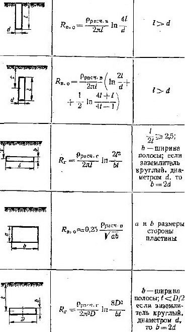
Table 8-4
The coefficients of using vertical entries, to and, in, zm placed in a row, without taking into account the influence of horizontal communications electrodes
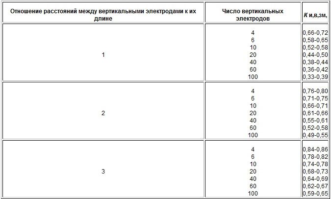
Table 8-5
The coefficients of using vertical grounding, to and, in, zm, placed on the contour, without taking into account the influence of horizontal communications electrodes
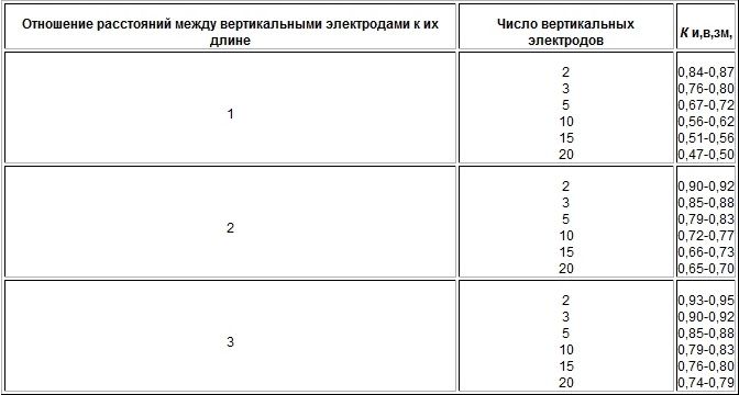
Table 8-6
The coefficients of use to and, g, zm of horizontal connecting electrodes, in a row of vertical electrodes
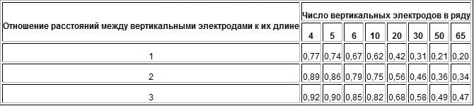
Table 8-7
The coefficients of use to and, g, zm of vertical connecting electrodes in the circuit of vertical electrodes
8. Refine the number of vertical electrodes, taking into account the coefficients of use in Table. 8-4 and 8-5:
![]()
The number of vertical electrodes from the location conditions is finally accepted.
9. For the settings above 1000 V with large closure currents to the Earth, the thermal resistance of connective conductors is checked by formula (8-11).
Example 1.. It is required to calculate the contour egging substation 110/10 kV substation with the following data: the greatest current through the ground during ground closures on the side of 110 kV - 3.2 ka, the greatest current through the ground during ground closures on the side of 10 kV - 42 A; Soil at the place of construction substation - Suglink; climatic zone 2; Additionally, the cable system is used as a ground - supports with a ground resistance of 1.2 ohms.
Solution 1. For 110 kV side, the ground resistance is required 0.5 ohms, for the side of 10 kV according to the formula (8-12) we have:
![]()
where the calculated voltage on the grounding device U is received is 125 V, since the grounding device is also used for substation settings to 1000 V.
Thus, the resistance rch \u003d 0.5 ohm is accepted as the calculated.
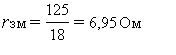
2. The resistance of the artificial earthing is calculated with the use of the support-support system
![]()
![]()
3. Recommended for preliminary calculations The resistivity of the soil at the site of the grounding of the entrance (Suglinka) on the table. 8-1 is 1000 ohm m. Increased coefficients K for horizontal extended electrodes with a depth of 0.8 m are equal to 4.5 and, respectively, 1.8 for vertical stem electrodes 2 - 3 m with a depth of embedding the vertex 0.5 - 0 , 8 m.
Estimated resistivity: for horizontal electrodes p qt \u003d 4.5x100 \u003d 450 ohm m; For vertical electrodes q \u003d 1.8x100 \u003d 180 ohm m.
4. The resistance to spreading one vertical electrode is determined - angle No. 50 with a length of 2.5 m during immersion below the ground level by 0.7 m by the formula from Table. 8-3:
where d \u003d d y, ed \u003d 0.95; B \u003d 0.95x0.95 \u003d 0.0475 m; T \u003d 0.7 + 2.5 / 2 \u003d 1.95 m;
5. The approximate number of vertical entries is determined at a pre-adopted coefficient of use to and, B, ZM \u003d 0.6:
![]()
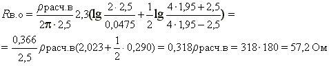
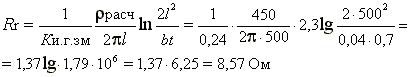
6. The resistance to spreading horizontal electrodes (strips 40x4 mm 2), welded to the upper ends of the corners. The coefficient of using the connecting strip in the circuit to and, r, zm with the number of the corners of about 100 and the ratio A / L \u003d 2 to table. 8-7 is 0.24. Resistance to spreading strips along the perimeter of the circuit (L \u003d 500 m) by the formula from Table. 8-3 Equal:
7. Refined resistance of vertical electrodes
![]()
8. The refined number of vertical electrodes is determined by the coefficient of use K and, G, ZM \u003d 0.52, adopted from Table. 8-5 at n \u003d 100 and a / l \u003d 2:
![]()
Finally, 116 corners are accepted.
In addition to the contour on the territory, a grid of longitudinal bands arranged at a distance of 0.8-1 m from the equipment, with cross-links every 6 m. In addition to leveling potentials in inputs and entrances, and in-depth edges are laid along the edges of the contour. These unaccounted horizontal electrodes reduce the overall ground resistance, their conductivity goes to the reserve of reliability.
9. Thermal strip resistance of 40 × 4 mm 2 is checked.
Minimum cross section Strips from thermal resistance conditions with to. h On the ground in formula (8-11) at the current time flow to the C. h. tp \u003d 1,1 is:
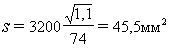
Thus, a strip 40 × 4 mm 2 The condition of thermal resistance satisfies.
Example 2.. It is required to calculate the grounding of the substation with two transformers 6 / 0.4 kV of 400 kVA with the following data: the greatest current through the ground when the ground is closed on the side of 6 kV 18 A; Soil at the facility - clay; climatic zone 3; Additionally, a water supply system with an embodiment of 9 ohms is used as a ground.
Decision. It is assumed to build a grounding from the outside of the building to which the substation is adjacent, with the location of the vertical electrodes in one row length of 20 m; Material - Round steel with a diameter of 20 mm, the immersion method is overlapping; The upper ends of the vertical rods are immersed to a depth of 0.7 m, welded to the horizontal electrode from the same steel.
1. For the side of 6 kV, grounding resistance is required, defined by formula (8-12):
where the calculated voltage on the grounding device is taken equal to 125 V, since the grounding device is carried out common for the parties 6 and 0.4 square meters.
According to PUE, the ground resistance should not exceed 4 ohm. Thus, the calculated is the resistance of grounding RZM \u003d 4 Ohm.
2. The resistance of the artificial earthing is calculated taking into account the use of water supply as a parallel grounding branch
3. Recommended for calculations of soil resistance at the site of grounding (clay) in the table. 8-1 is 70 ohms * m. Increased coefficients K for the 3rd climatic zone on Table. 8-2 are taken equal to 2.2 for horizontal electrodes with a depth of 11 m and 1.5 for vertical electrodes with a length of 2-3 m with the depth of the attachment of their upper end of 0.5-0.8 m.
Settlement resistances of soil:
for horizontal electrodes p qt \u003d 2.2 × 70 \u003d 154 Ohm * m;
for vertical electrodes p qt \u003d 1.5x70 \u003d 105 Ohm * m.
4. The resistance to spreading one rod with a diameter of 20 mm, 2 m long during immersion below the ground level is 0.7 m by the formula from Table. 8-3:
5. The approximate number of vertical entries is determined at a pre-adopted coefficient of use to and. G. ZM \u003d 0.9
![]()
6. The resistance to spreading the horizontal electrode from the circular steel with a diameter of 20 mm, welded to the upper ends of the vertical rods is determined.
The utilization coefficient of the horizontal electrode in a row from the rods with the number of them is approximately 6 and the distance between the rods to the length of the rods A / L \u003d 20 / 5x2 \u003d 2 in accordance with the table. 8-6 is taken equal to 0.85.
The resistance to spreading the horizontal electrode is determined by the formula from Table. 8-3 and 8-8:
Table 8-8.
Raising resistance coefficients with respect to measured resistivity of soil (or grounding resistance) for the middle strip of the USSR
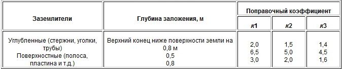
Notes: 1) K 1 applies if the measured value of P (RX) corresponds to about minimal value (the soil is wet - the measurement time was preceded by the loss of a large amount of precipitation);
2) K2 applies if the measured value of P (RX) corresponds to approximately the average value (the ground of the average humidity - the measurement time was preceded by the loss of a small amount of precipitation);
3) K3 is used if the measured value of P (RX) corresponds to about the greatest value (the dry ground - the measurement time was preceded by a slight amount of precipitation).
7. Refined resistance to spreading vertical electrodes
8. The refined number of vertical electrodes is determined by the utilization factor and. G. ZM \u003d 0.83, adopted from table. 8-4 at n \u003d 5 and a / l \u003d 20 / 2x4 \u003d 2.5 (n \u003d 5 instead 6 is taken from the condition for reducing the number of vertical electrodes when taking into account the conductivity of the horizontal electrode)
Four vertical rods are finally accepted, while the resistance to spreading is slightly less than the calculated one.
Exposure from the reference book on the power supply of industrial enterprises
under the general edition of A. A. Fedorov and G. V. Serbinovsky
| Discuss on the forum |
|
| |
|
Established grounding is found today in almost every home. And it is not surprising, as it ensures the safe operation of electrical equipment and directly posting. In this article, let's talk about this an important elementlike a earthing.
It is known that without such an element, the grounding design cannot exist, and even more so carry out the tasks.
Egg - metal conductor or reinforced pin, covered in the desired depth of ground. It can work singly or in a complex with other electrodes, for example, in a triangular circuit. Before this element, the main function is to contact with high-voltage electricity, but it is impossible to judge its optimal functionality, if the resistance is not defined.
Horizontal and vertical grounding
Note! The earthing resistance must be very low. Only so you can count on the full protection of the home electrical circuit.
Deciding with the question of what is called the grounding manner to study his species.
Types of Grounders: Subtleties of their use
Each type of electrode has a specific purpose that we will look at:
- The deep earthing is a design that provides a complex installation, but having a lot of advantages. Of the features of this type of electrodes, it is possible to allocate that their installation occupies a much less space than the standard grounding circuit. Proved the effectiveness of this conductor in places with the smallest resistance of the soil. Today, in regulatory acts it is prescribed that it is possible to use a similar element in the basement and the basement.
Important! Conducting the installation of a deep earthing is exclusively using drilling rigs.
For home conditions, the ideal solution remains the use of vertical entrancers, which you can not say about the industrial direction. Here, on the contrary, it is appropriate for the installation of anodic electrode. It is used to protect pipelines and underground structures. In fact, the material is quite reliable and resistant to corrosion.
Features of electrolytic grounding
This type of ground is effectively used in places of sandy, perplexed and rocky soil. Also in conditions where the soil has high resistivity and requires special equipment for installing conventional electrodes.
Important! Using standard electrodes for the grounding circuit device in sandy and other types of soil with high resistance, you will have to set their set (order 100).
A little about the advantages of electrolytic grounding

Hemispheric earthing
In fact, like a pin grounding, electrolytic has some very important advantages.
- This type of electrodes provides minimal resistance to the soil, up to about 10 times less, in contrast to traditional earthing.
- It is performed from a special mixture preceding the formation of corrosion.
- Has a long service life. If the steel ground electrode serves about 5-7 years, then electrolytic order 50.
- Does not require high depth for installation, it is enough to build the grounding agent by half the meter.
Principle of electrode operation
The main element of this type of ground is the trumpet of the M-shaped form. It is driven by a certain depth, which is pre-filled with a mixture of mineral salts. The substance absorbs water from the surrounding soil, while creating leaching, as a result of which the electrolyte is formed. Then the same electrode penetrates into the soil, increasing its current-carrying properties. Resistivity Reduced, and as a result, the freezing of the soil layer is reduced.
Often after the completion of the project, the soil is taking down next to the structure. Unfortunately, it is very dangerous for the foundation and threatens a sedimentation at home. Therefore, electricians are recommended when designing electrolytic grounding, take into account the factor of damage to buildings, and, consequently, they need to be removed from the placement locations.
In conditions of strong soil freezing, horizontal electrodes are used. They are accessible and easy to install. However, with every opportunity to work with drilling equipment, it is best to install a vertical earthing.
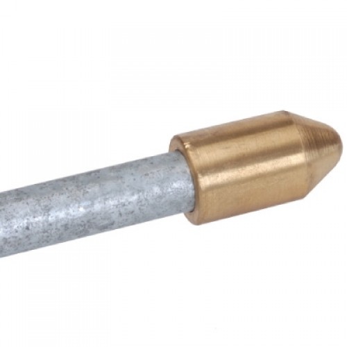
Earther
How to check the electrode?
Electrolytic type entries require regular performance test. Conduct its maintenance once in 2-3 years. It is important to determine if the mixture turned into an electrolyte. If the electrolyte formed, the mixture is replaced, that is, a new composition of salts is added. Similarly, each electrode is checked if it is not alone. Thus, the installation will serve a few more years.
Important! It is enough to fill the electrode with mineral salts of high quality, and it will last about 10-15 years. But neglected regular service it is impossible.
Group and Single Ground: Characteristics
Each separate type of earthing or electrode has its own characteristics that it is important to consider when designing a grounding circuit. Consider each of them with inconsistencies:
See the grounding schemes with symbols below.
What is corrosion and which consequences for earthing?
More from school bench, namely, from the lessons of geography, we know that corrosion is a natural destructive impact on metal objects and their shells that are long in the ground. Most often, this defect material occurs in places of high humidity.
Typically, corrosion occurs after 9-10 years of use metal designand bears certain consequences for the grounding device. For example, large damage to the ground loop plus the presence of rust entails an increase in resistance.
Important! In the zone where there is a risk of a speedy corrosion occurrence, it is advisable to use materials for the construction of a stainless steel grounding circuit.
It happens when corrosion penetrates and under the shell ground conductor leading to the main electric shield or transformer. In such a situation, experienced electricians recommend using anti-corrosion lubricant. Sometimes the locations are processed


