Ensuring reliable power supply to the consumer - a guarantee of stable operation. You are a consumer, it does not matter a private person or a commercial structure, only one thing remains important: high-quality power supply, without interruption, without accidents. This is properly operational and continuous control over the technical condition of the entire electrical equipment.
One of the items of monitoring the state of electrical equipment conducted is checking grounding electrical installation devices.
Monitoring status grounding devices begins with checking the status of elements grounding devices. In the process of checking, the electrolaboratory specialists will conduct a visual inspection, within the accessibility, each element of the device. Their location, quantity and other characteristics must comply with project data passport of the grounding device And should not contradict the requirements of the rules of the device of electrical installations (PUE) and the rules for the technical operation of consumer electrical installations (PTEEP). The following elements are subject to mandatory inspection. grounding device electrical installations: The main grounding tire - on the correspondence of the cross section of the tire, the integrity throughout the visible part, the strength of the compounds of all sections; Grounding conductors from grounded element to the main grounding bus are checked similarly; Punching fuses are checked for compliance with the rated voltage of electrical installation and integrity; Protective shutdown devices (UZO) are checked on the test by the "Test" button provided in the design of the device.
The connection of the tires must be made by welding therapy, the strength and reliability of welded connections between the grounding circuit areas is checked by the hammer blows. To avoid magnification resistance to the grounding device, Welded seam should be solid, smooth without scale and make up length at least two tire widths. When used as a grounding conductor, the rod round cross sectionThe length of the weld should be at least six diameters. All conductors are painted black, painting parts in the ground is not allowed.
Connection with ground elements is allowed to produce a bolt / soldering. Soldering is most often used to connect with a cable braid and bolts for connections in cabinets / shields of electrical equipment, connections of electric motors.
All results of inspection of elements grounding devicesare entered in substituer check protocol. Electrical Babor Powerbliament Makes this check on low prices and with high quality. Call or and our experts will contact you within an hour.
Grounding devices BL supports consist - from earthing in soil and grounding conductors connecting grounded parts of supports with a ground.
Metal conductors from a round (diameter of at least 10 mm) or galvanized wire with a diameter of at least 6 mm are used - their cross section should be at least 35 mm 2, and strip steel, pipes, corners, as well as base elements in the ground Metal and reinforced concrete supports (subits, foundations, parts of racks). Grounders can be contour, podfundant, deep, extended.
The design values \u200b\u200bof the resistance of grounding devices of the BL support are given in Table. 30. Deviations of the design value of the impedance of the grounding device should not exceed 10%. The earthing must be replaced if more than 50% of its cross section is destroyed.
On WL with wooden supports, it is recommended to perform a bolted connection of grounding descents at a height of 2 ... 2.5 m from the ground; On metal and reinforced concrete supports, the connection of grounding descents can be performed both welded and bolted.
Malfunctions of grounding devices that can be identified by external inspection, these are damage or cliffs of grounding descents on the support and in the Earth; unsatisfactory contact in bolted protective cable connections with turbulent descents or support bodies; unsatisfactory contact of the mural compound with the body of the support (reinforced concrete support fittings); Exceeding a superdeumous value of resistance to grounding support; the absence of brackets attaching grounding descents to the support; the destruction of the corrosion of the grounding device; the protrusion of earthingers above the surface of the Earth; Defects in the installation of tubular arresters on the supports, the inconsistency of the size of the external spark gap given, poor fixation of the horns, etc.
Armature of the prefixes (a) and supports (b), which are upgraded grounding conductors:
1 - contour of support (consoles; 2 - reinforcement; 3 - mortgage electrode
Legend: C - welding place; P is the place of attachment (binding) of the electrode with the wire to the valve; KV - Contact pin with ground electrode for protective bandage (KSB)
Reinforced concrete steps, piles and monolithic foundations are significantly less susceptible to the destructive action of groundwater, since their metal parts are protected by a large layer of concrete. In cases where the thickness of the protective layer of concrete is insufficient - less than 30 mm, the foundation surface is covered with a waterproofing layer of bitumen to prevent rusting of the footsteps and piles.
W. concrete foundations It is often damaged by their overhead part. As a result of the strikes, chips of concrete occur most often about the supports. The appearance of cracks in the above-ground part of the foundation leads to moisture in them, expanding cracks during moisture freezing and the subsequent coloring of concrete. Violation of manufacturing technology monolithic foundations leads to their bundle, climbing the upper part of the foundation and the fall of the supports. To populip the concrete, the moisture and freezing of moisture in open wells around the anchor bolts also leads. When cracking and concrete chips appear, the foundations are repaired.
The main defect of the anchor plates are cracks in metal brackets for fastening the delay of the supports. These cracks can be caused by a violation of the manufacturing technology of these brackets at the factory. Rales of brackets having cracks lead to the fall of the supports. The identification of such cracks is a very difficult case under operating conditions. The personnel experience is needed here.
When entering the line into operation, an installation organization after the end of the installation of the grounding device (memory) transmits to the operational organization (PES):
circuit of the grounding device;
Executive drawings of the grounding device;
Measurement protocols specific resistance soil, where grounding device is mounted;
The protocol for measuring the resistance of the grounding device.
These initial data are made to the passport of the grounding device, where indicate the inclusion date to work, the resistance value of the memory and the subsequent measurements of the date of inspections and repairs. The passport of the grounding device is given in Table.
Requirements for grounding devices. The grounds of BL, as a rule, should be at a depth of at least 0.5 m, and in arable land - at least 1 m. In the case of installation of supports in rock soils, the radial entrances are allowed directly under the collapsible layer over the rocks with a layer thickness of at least 0.5 m. At the smaller thickness of this layer or its absence, the ground gasket is recommended over the surface of the cliff with their cement mortar.
The addition of supports for grounding devices is performed by bolted mounts using a strip steel segments welded at metal supports - to the legs of the support, and at reinforced concrete - to special conclusions or grounding conductors (descents) connected to the reinforcement of the support. On wooden supports, ground conductors at a height of 2 ... 2.5 m from the ground should have detachable bolt connections.
To control the grounding device, it is performed: measurements of its resistance at least 1 time in 12 years; Selective checking with the opening of the soil to assess the corrosion state of the earthing elements located in the ground; Checking the presence and status of chains between the earthing and grounded elements, the compounds of natural earthingers with a grounding device - at least 1 time in 12 years; Voltage measurements
Table passport number
Grounding device
Project implemented
(Name of the project organization)
Date of the grounding device
Date of inclusion in the work
I. Basic data
Place of grounding.
Characteristic of soil
Electrode type Number of electrodes pcs
Electrode dimensions: length m; outside diameter MM.
Depth of the hitch (embracing) of electrodes m
Distance between MM electrodes
Connecting strips: Material; Width mm:
MM thickness
Depth of the embossing bands of the circuit mm
Notes I:
II. Test data
Name of quantities |
Dimension |
|||||
data |
||||||
1. The established current k.z. On the side of the KV. |
||||||
2. Resistance of the grounding device |
||||||
3. Maximum potential of the grounding device |
||||||
4. Maximum tension voltage |
||||||
5. Maximum step stress at the KR substation |
||||||
6. The value of the maximum potential that can be made (rendered) extended earthing (rails, pipelines, etc.) |
||||||
7. Test method |
||||||
Notes:.
Touching in electrical installations, the grounding device of which is made according to the standards for the tension voltage; check (calculated) voltage compliance on the maintenance device requirements after installation, reorganization and overhaul of the grounding device, but at least 1 time in 12 years; In the installations up to 1000 in checking the punching fuses and the total resistance of the loop "Phase - zero" - at least 1 time in 6 years.
Measuring the resistance of grounding devices on VL are performed after installation, reorganization and overhaul; on VL 110 kV and higher when traces of overlapping or destruction of insulators of electrodes are detected on the cable supports; 35 kV lines and lower - at least 1 time in 12 years at the supports with disconnectors, protective intervals, tubular and valve arresters and in supports with repeated earthing tolls - at least 1 time in 6 years; Selectively on 2% of reinforced concrete and metallic supports in the locality, in areas of the WL with the most aggressive, landslide, inventive or poorly conductive soils - at least 1 time in 12 years. Measurements are performed during periods of the greatest soil drying or taking into account the soil drying veluses shown in Table.
The value of the correction coefficient of the COP
Type of grounding |
Shining depth |
COP when measuring in the ground |
||
middle humidity |
||||
Radius (superficial) |
||||
Vertical (tube, corner, rod) |
||||
The depth of stagging grounders under normal conditions is 0.5 ... 0.8 m and the depth of the soil drying during the thunder period is determined. All connections in the underground part are welding.
For vertical electrodes it is recommended to choose steel tubes A diameter of 30 ... 60 mm and a length of 2 ... 3 m, and for horizontal electrodes - a steel tape with a thickness of at least 4 and a width of 20 ... 40 mm or round steel with a diameter of 10 ... 20 mm.
Inspection of grounding devices includes checking the state of contact compounds of grounding conductors, their attachments, the degree of impact on them corrosion, no heating. In the settings voltage up to 1 000 V, the state of spark gaps and punching fuses are also checked. External inspection of the grounding device is made together with the inspection of electrical equipment electrical installations.
At the current repair of grounds, it is replaced by the faulty elements of the grounding device; tightening weakened bolted connections; Updating coloring.
Overhaul of grounds, as a rule, are planning in advance and spend after thorough preparation for it. As an exception is carried out extraordinary repairs, the need to be detected during measurements, inspections and current repairs. When preparing for overhaul, grounding electrodes manufactures, grounding conductors, check mechanisms and devices, constitute a repair schedule, conduct testing of personnel knowledge, etc. The resistance of the grounding circuits is checked in preparation in different, including the most unfavorable, time of year, since measurements in wet soil and recalculate with the help of approximate seasonal coefficients do not always give accurate results, and when checking in winter or in dry summer period Resistance may be excessive. Reducing the resistance of grounds to the norm is achieved during the overhaul of the device of additional electrodes or a new grounding circuit. At the same time, the location and design of the grounding circuit is determined by the executive drawings and acts of hidden work, therefore, the technical documentation obtained by the operational organization at the acceptance of the facility must be kept during the entire period of operation.
When planning capital repairs, the approximate service life of the grounding agents is calculated using the results of observations of them in specific conditions or indicative average data. So, under normal conditions, for example, industrial substations, corrosion of unprotected earthing agents is in the ground an average of about 2.5 mm in 10 years. Consequently, strip steel with a thickness of 5 mm, rusting on both sides, in 10 years it will completely fail, and in 5 years it will lose half of its thickness and mass. With a strip thickness of 4 mm, such a loss will occur in 4 years, with a thickness of 6 mm - for 6 years, etc. It will also rust and the shelves of the angular steel and the walls of the pipes.
Grounding electrodes are replaced without waiting for their complete destruction, within the time defined by local instructions. Usually, the replacement is carried out with a decrease by half the thickness of the strip steel or the thickness of the pipe wall, which coincide with a decrease in halvening the ground mass. For the earthinglers from the round steel, the calculation of the term of replacement is carried out by a decrease in the diameter, but the masses are twice, which occurs significantly earlier. According to the current standards, the entry element must be replaced if more than 50% of its cross section is destroyed.
To determine the technical condition of the grounding device, it should be examined with selective opening of the soil, measuring the parameters of the grounding device in accordance with the standards for testing electrical equipment. Inspections with selective opening of the soil in places that are most susceptible to corrosion, as well as near the grounding of power transformers neutrals, connections of arresters and overvoltage limiters should be carried out in accordance with the schedule of planning-preventive work (hereinafter referred to as RPR), but at least once every 12 years . The magnitude of the grounding device subjected to selective opening of the soil (except for VL in locality) is determined by the decision of the technical leader of the consumer.
Testing grounding devices are carried out after the end of the current and overhaul.
After the current repair, perform:
- Checking the continuity of the chain in the conductors connecting the elements of the equipment with a grounding device, with a climbing method with a slight hammer of grounding conductors in places of their connection or branch to determine the mechanical strength.
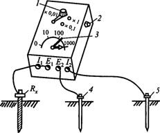
Fig. 1. Scheme of measuring the resistance of grounding conductors of the MS-08 type device:
7 switch; 2-republic potential chain; 3-red feature on the scale; 4-probe; 5 - auxiliary earthing man; RX-Tested Ground Resistance
2. Measurement of transitional resistance of grounding conductors between the equipment and the ground circuit.
Measurement of the grounding device resistance using the MS-08 type ground meter, which uses an ammeter-voltmeter method using auxiliary earthing and a potential electrode (probe). The scale of the device will be cleaned with three limits of measurement: 0-1000, 0-100, 0-10 ohms. Measurements are carried out according to the scheme (Fig. 1). When measuring large resistances, the E \\, / j clamps are connected to the jumper and attach to the ground-test) Rx, and to eliminate the error made by connecting wires, use another circuit (Fig. 2). To create a load chain at some distance from it, auxiliary earthing agent 5 is clogged (see Fig. 1). Probe 4 is needed to measure the voltage drop in the earthing in the zero potential zone. 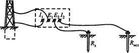
Fig. 2. Diagram of measuring the resistance of ground conductors by the MS-08 device with great accuracy
To reduce errors in measurements, the auxiliary electrodes (probe and auxiliary earthing) should be between themselves and the test earthing at a certain distance (Fig. 3). These distances are:
a) Complexed earthing (Fig. 3, a):
b) complex earthing, single-collar circuit (Fig. 3, 6) \\ ![]()
in) single earthing (Fig. 3, c): ![]()
d) focused earthing (Fig. 3, d): ![]()
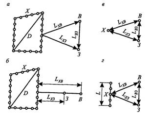
Fig. 3. Mutual positioning the test earthing and auxiliary electrodes and minimum distances between them: a - complex earthing, two-beam scheme; B - the same, single-collar scheme; in - single earthing man; Mr. focused earthing; D -Diagonal contour earthing; X-tested entry; 3 - probe; B - auxiliary earthing
With a small resistance of the measuring circuit under ground, the long connecting wires of the measuring circuit can make a significant error in the measurement results, therefore, in these cases, it is recommended to connect an earthing man in two separate wires from the clips of the device 1x and E1.
Measurement of the total resistance of the loop "Phase - zero" in the settings of 1000 V with a deaf neutral grounding. To check the compliance of grounding devices, the chain protection requirements for emergency modes it is necessary to measure the amount of full resistance of the entire CZ current circuit, and all the factors are automatically taken into account, from which this resistance depends, including the conductivity of all kinds of parallel pathways of the circuit current-metal structures, shells, cables, and T.P.
Most easily measure the resistance of the chain "Phase-zero" when the line is disconnected. At first, the resistance of the ZN chain is measured by the M / W CLO of the point Z5 point without taking into account the resistance of the transformer (Fig. 4) by the ammeter and voltmeter method. Measurement is carried out with a reduced voltage 12 or 36 in a drop-down transformer T2, which is included as closer to the working transformer in order to take into account the resistance of the entire network. The voltage in the test chain to control the value of the current is raised gradually, for which the RR retain is installed in the transformer circuit. Natural conductors from the grounding network are not disconnected. Previously check the insulation resistance of the test line and, if necessary, eliminate defects.
To check the melting of the smooth insert of the F1 fuse (or turn off the circuit breaker), an artificial closure at point 1 is performed on the hardware housing with a disconnected switches S1. To check the combustion of the F2 Fuse insert, the same closure on the housing is made at point 3 as more remote than the point 2. After the voltage is supplied to the circuit, the current / measuring and the UH3M voltage is measured for each point. The resistance of the chain "phase - zero" wire from points m; W; Vdo point P is determined by the formula
(3.18)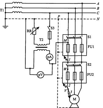
Fig. 4. Diagram of measuring the resistance of the chain "Phase-zero" with disconnection
Equipment
To calculate a single-phase closure current, determine estimated resistance Transformerizes tables, after which, knowing Z "and, determine a single-phase closure current:
Since the measurement is carried out when the load is disconnected, corrections are made to the counting results: 0.95 UF is received as a phase voltage (to consider it real decline under load); To take into account the transitional resistance at the site of the closure and error of the instruments, a lower coefficient is introduced approximately equal to 0.9.
Thus, the calculated formula has the form: 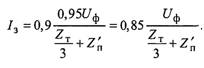
To ensure the reliability of the work of protection, the smallest current of single-phase KZ / 3 must several times higher than the current of its response. Therefore, the current / 3 must satisfy the condition
where / n _ the rated current of the smooth insert, and;
K-coefficient equal to the fused inserts of at least 3 for circuit breakers - 1,4.
After overhaul, the ground loop is performed checking the state of the breakdown fuses in the installations of up to 1000 V and spark gaps in the RU-3.3 square meters of suction circuit.
Punching fuses are installed directly on the caps of the tank transformers. One fuse contact is attached to the outputs of low voltage windings, the other to the transformer Baku. The fuse is designed for current up to 220 and a duration of 30 minutes. The sample of the fuse occurs in the layers of the airbase at a voltage of 350-500 V (U to 220 V) and 700-1000 V (U to 500 V).
Checking the status of punching fuses start with external inspection of the fuse. If subgars are detected on the contact surface of the fuse, they are cleaned with a file. Check the maintenance of mica gasket. The damaged gasket is replaced. The thickness of the mica, determining the level of the punch voltage, should be 0.08-0.02 mm at rated voltage up to 220 V and 0.21 ± 0.03 mm at a voltage of up to 500 V.
The health of spark gaps included between the suction and the external ground loop on the traction substations direct current, controlled by an electrolympoise included in parallel gaps. Folding lamp indicates breakdown.
On traction substations alternating current Check the integrity of the railway railway chains and statione tracks with butt connector and track chokes with a substance grounding circuit.


