.8.1. Basic provisions
Fig. 7.1. . An example of the deformation of the winding
Violation of the geometry of the power transformer windings as a result of mechanical effects in the flow of large currents or disruption of the pressing mechanism is a serious defect leading to failures due to the procurement or loss of winding stability.
When there are electrodynamic forces on the windings of the transformer of large currents (for example, the currents of external KZ), which can cause the deformation of individual conductors, coils or all over the winding (Fig. 7.1). The probability of damage under such influences depends not only on the value of the current, but also on the number of external KZ, creating currents through the transformer. The weakening of the force of the press leads to increased vibrations of the winding and, as a result, turning to the vit conjunction due to abrasion of insulation [L.1].
Dangerous defects include axial displacements of individual coils and their radial deformations. More than 80% of the damage to powerful transformers with short circuits is associated with the loss of radial stability of windings. It is important to establish the initial deformations of the windings in order to prevent the emergency output of the transformer in a timely manner with destruction, significantly reducing repairs and impede the cause of the cause of the accident. The main parameter characterizing the deformation of the windings is the resistance of the ZK transformer. By changing ZK, you can determine the degree of deformation of the windings. The allowable change in ZK depends on the design and technology of manufacturing windings. Periodic measurement will allow you to timely identify damage to the transformer and bring it into repair.
1. Perform the measurement of ZK on all transformers and autotransformers with a capacity of 63 MBA and more, a voltage class of 110 kV and higher:
before commissioning;
under capital repairs;
after leakage through the transformer of currents of 0.7 and more calculated current of the transformer CZ.
.8.2. Measuring method
The short circuit method is based on the current measurement through one of the transformer windings when the conclusions of the other winding are closed. Measurement is performed with a low voltage of industrial frequency. According to the measurement results, the value of the resistance of the short circuit z k is calculated.It should be noted that the value z is not dependent on the voltage value, but can differ significantly depending on the method of its supply [L.3].
When conducting measurements, it is necessary to consider the following:
1. Measurement z K is performed using ammeters and voltmeters included in the measuring circuit on a disconnected and fully expanded transformer. Power supply voltage - 380 V, the accuracy class of applied instruments not lower than 0.5. You can use when measuring the set of devices K505 or K50. In the absence of measuring kits, K505 or K50 measurements can be made, having one ammeter and one voltmeter, by one-time connection to phases (after disconnecting the supply voltage).
2. Measurements z to three-phase transformers must be made from the winding side connected to the "star" and having a zero wire (Fig. 7.2).
3. When measured, the voltage should be submitted for all three phases, the current measurement and voltage to produce phazno with the mandatory use of zero wire. With all measurements of the resistance of the KZ "Triangle" on the NN windings should be assembled.
Fig. 7.2. . Measurement scheme
4. The required current value for measurement should be determined, based on ensuring the normal reference to the instruments (ammeter and voltmeter), the instrument arrow should be on the second half of the scale. Z K is determined by the formula:
5. The boring section, installed on the outputs, should be at least 30% of the transformer winding wire secting. The winding wire section should be determined by the value of its rated current, based on the average current density in the winding, equal to 3 A / mm 2. All attachments of feed wires and blizzard must be made under the bolt. When used as a bunch of aluminum wires (tires), their cross section should be increased compared to copper by 30%. Spin length should be minimal.
6. The passport value of Z CP is calculated by the formula:
![]() , Oh.
, Oh.
7. In order to more complete control of the state of the transformer, the measurements of Z K should be made on three stages of voltage control: nominal and two extreme. The rated current of the winding (I 'number), if necessary, is determined by the formula
![]()
8. When measuring, it is necessary to record the frequency of the supply network. If during measurements, the frequency of the network (F) was different from the nominal (50 Hz), the measured values \u200b\u200bZ 'K must be brought to the nominal frequency by the formula:
9. An assessment of the state of the transformer windings to produce by comparing z values \u200b\u200bto phases with data generated earlier at the place of measurements or in their absence with passport data. The change of Z K is calculated by the formula:
![]()
The value of z to 3% indicates the presence of unacceptable deformations in the windings. When compared with the passport data for the initial value of Z K, indicating the deformation of the windings, it is necessary to take 5%, since according to the factory measurements of the resistance of individual phases of transformers may differ to 2%.
For three-winding transformers during the deformation of the average by arrangement of the winding, the sign z to the positive when measuring Z to the pair, where the average winding is internal, and negative when measuring z to the pair, where the average winding is outer.
.8.3. Examples
When monitoring the TDCTG-240000/330/150 transformer, changes were revealed by ZK, showing the presence of the winding deformation (Table 7.1) [L.1].Changing Z K between VN and CH windings is irrelevant, it is lower than the measurement accuracy. There are significant changes to Z to between the windings of the VN-NN and SN-NN, and for the CH winding, which is closer to the NN winding, changes z to more.
Table 7. 1.
| Measurement scheme | Phase | ZK, Oh. | ZB, Oh. | zk,% |
| BUT | 50.3 | - 0,98 |
||
| VN - SN | IN | 50.7 | 50.8 | - 0.20 |
| FROM | 50.5 | - 0.59 |
||
| BUT | 161 | - 0,62 |
||
| VN - NN. | IN | 171 | 162 | 5.56 |
| FROM | 170 | 4.95 |
||
| BUT | 24.1 | 1,3 |
||
| SN | IN | 26.9 | 23.8 | 13.0 |
| FROM | 26.3 | 10.5 |
Diagnosis: the deformation of the winding of the NN phase B and C.
The measurement results on the TDCTN -25000/330/110 transformer showed that there are significant changes to Z K, and the greatest asymmetry by phases was revealed in the measurement schemes with the participation of the CH winding.
Table 7. 2.
| Measurement scheme | Phase | ZK, Oh. | ZB, Oh. | zk,% |
| A. | 86,3 | 3,5 |
||
| VN - SN | B. | 88,1 | 83,4 | 5,6 |
| C. | 90,6 | 8,6 |
||
| A. | 272 | - 4,9 |
||
| VN - NN. | B. | 277 | 286 | - 3,1 |
| C. | 272 | - 4,9 |
||
| A. | 22,0 | - 3,1 |
||
| SN | B. | 22,0 | 22,7 | - 3,1 |
| C. | 21,0 | - 7,5 |
||
| A. | 12,9 | - 5,1 |
||
| CH - RO | B. | 12,7 | 13,6 | - 6,6 |
| C. | 12,2 | - 10,3 |
Additional control showed the greatest changes to the Z K between the adjusting winding and the CH (CH-PO) winding. The positive values \u200b\u200bof the Z K should correspond to deformations that increase the distance between the corresponding windings; Negative - their rapprochement. Signs of changes z k correspond to the mutual location of the windings in the diagnosed transformer.
Diagnosis: deformation of the CH winding, especially in phase S.
These recommendations are based on the experience of identifying deformable windings of transformers 125 - 1000 MBA over the past 10 years in the energy systems of Ukraine and Russia. The most unstable to the operational through KZ are transformers with a voltage of 220 kV and higher.For three-phase transformers, the interpretation of measurement results start with comparison Z K values \u200b\u200bbetween phases for each mode. The discrepancy between the phases exceeds 3% should be considered dangerous to the same extent as an increase in Z to 3% when compared with the previous measurement. Comparison between phases to perform immediately, directly at the point of measurement. With zk\u003e 3% (between phases), repeatedly repeat each measurement to increase the reliability and accuracy of the result.
For increasing transformers with a double concentric winding VN (the location of the VN2-NN-NN1 windings), the danger value z to about 2 times less than with the usual location of the windings. Therefore, for them measurements Z K should be carried out especially carefully. Such transformers include, for example, TDC-400000/330.
Strong mechanical deformations cause electrical damage to windings. Therefore, with z to\u003e 10% and especially 15% should be repeated not only to measure z K, but also others electrical measurements (Resistances of windings, insulation resistance).
.8.5. Filling machine form of measurement results
To enhance the measurement results in the database, you must fill in the template in accordance with the rules given in the "User Instructions". The shape of the template is given below.Be sure to enter the dates of measurement.
For a three-winding transformer, the user is entered by the measurement voltage (U) and measured current (i) for all three schemes (VN-NN, SN-NN and VN-CH). For the two-winding voltage and current values \u200b\u200bare entered only for the first measurement circuit (VN-NN).
For a three-phase transformer, three lines on the scheme are filled, and for a single-phase - line corresponding to phase A.
The short circuit resistance (z k) is calculated during the examination and is entered into the form field.

.8.6. Features algorithm
To take into account possible inaccuracies of measurements in order to obtain a reliable result in the algorithm, it is possible to adjust the brothering standards for a short circuit resistance. The value of 3 (5)% is taken as the initial one for all possible combinations of windings. In the event that z to an absolute value exceeds the brave standard for all pairs of windings, then in the algorithm it provides its increase in 0.5% increments until at least one of the winding combinations will not satisfy this standard..8.7. Literature
Svy P. M. Methods and means of diagnosing high voltage equipment. M.: Energoatomizdat, 1992. - 240 s.
Operating Fomolar C-02-88 (E). On measurements of the resistance of the CZ transformers. 1987. - 10 p.
Sokolov V. V., TsURPAL S. V., Konov Yu. S., Korolenko V.V. Determination of deformations of the windings of large force transformers. Electrical stations, 1988, N 6. - P. 52-56.
Hungry Yu. M. Control over the state of transformers. M.: Energoatomizdat, 1988. - 88 p.
Page 1.
Measuring the short-circuit current is produced in two closures for filtering the aperiodic component of the short circuit current: during the first time, the shift angle of the steady current value is measured relative to the voltage during the second - the re-short circuit at the time corresponding to the measured shift angle value.
When measuring the short circuit current, the voltage is equal to zero. If the sample resistance is so low that the short-circuit conditions cannot be performed, then the photomagnetic EMF is measured and the conductivity of the illuminated sample in the magnetic field.
On low-frequency machines, when measuring short-circuit currents, the highest pulse duration is set, allowed for this stage of the transformer. On single-phase machines, the definition of short circuit currents is performed for each stage of the transformer with minimal and maximum separation of the controller heating of the interrupter. For condenser machines, short circuit currents determine the maximum transformation coefficient, maximum voltage for each group of capacitors battery and for all transformation coefficients (steps) when one of the condenser groups is turned on at maximum charging voltage.
The short-circuit current meter of the Digital Sh41160 is designed to measure the short circuit current of the phase-zero circuit in the AC networks with the deighted-earth neutral trailsiformator.
The basis of this method for measuring the diffusion length of non-core charge carriers is the measurement of the short circuit current P - n - transition or structures with a valve barrier when illuminated by its light. The advantage of the method consists in the possibility of measuring the small diffusion lengths of non-core charge carriers in thin epitaxial layers. The method uses the principle of operation of the photodiode. Consider this method in relation to the epitax-sialic layers of Gallium arsenide.
Formulas (4.74) and (4.75) are used to find the diffusion length according to the results of measuring the short circuit current. To determine L on the base (4.74) or (4.75), except / FME and, it is necessary to find the values \u200b\u200bof the control of the charge carriers, the intensity of light and other values \u200b\u200b(from independent measurements) or use known data.
In general, at least two independent measurements are required. Usually, a short circuit current is used as an additional use in the photoelectric effect.
EMF Hall sensors can also be used to study magnetic fields in electrical machines and control their operation mode. Locke's use describes the use of sensors from N - Ge and Ra - Inas to measure brush short circuit currents in DC electrical machines. These currents arising in all collector machines are harmful. The fight against this undesirable phenomenon requires knowledge of the magnitude of the brush currents of short circuit.
| Symmetrical short circuit. |
The satisfaction of this requirement is not difficult to ensure that the conductors entering the clips of the machines were not only a proper cross section, but also the least possible length, and if for any reason they have to give more or less significant length, then to reduce scattering threads should be closer These conductors are as close as possible, if possible throughout their length. The length of the conductors of the external chain of the short circuit is determined by the lowest distance between the closed clamps and current transformers serving to measure the short circuit current.
Passportization of electrical devices of the contact machine ends with voltage measurements between the electrodes of the welding machine and short circuit currents along the steps (see the CH. The AC voltmeter is connected to the voltmeter of the AC to the 30 V. Measurement of short circuit currents in steps is made in one of the methods discussed in ch. To The start of measurements need to set the maximum sizes of the welding circuit.
In some cases, when measuring C / 0 and F / 2 are produced on powerful substations with small values \u200b\u200bof zero and reverse sequences, the lower limit of measurement of voltmeters may be insufficient to measure voltages at remote short circuits. In such cases, in addition to fixing voltmeters, fixing ammeters must be included, providing measurements of currents / ° C or / 2 at remote closures, when the corresponding voltages U0 or [72 fall into the insensitivity zone of fixing voltmeters. It should be noted that methodologically more accurate results in determining the distance to the location of the closure are obtained in cases where the voltages are measured at close short circuits, and with remote currents. The range of measurement of short circuit currents is determined by the ratio of the parameters of the line and system, as well as the value of the transition resistance at the closure site.
Pages: 1.
Before conducting the experience of the XX transformer in operation, it is necessary to unagine its magnetic pipe from residual magnetization, resulting from a sudden reset of the supply voltage (disconnecting the transformer from the network) and the current break when it is not null.
Removing residual magnetization is carried out by passing the direct current of opposite polarities on one of the windings of each transformer magnetic pipeline rod.
The process of demagnetization is carried out in several cycles. The initial correction current must be at least 150% of the current XX of the transformer at rated voltage recalculated for the winding on which demagnetization will be made. The same current is equal to 150% of the rated current XX is fed to phases A (+) - 0 (-), in (+) - 0 (-), with (+) - 0 (-), alternately, but not A-B, in -We, s - a. The polarity A (-) - 0 (+), in (-) - 0 (+), c (-) - 0 (+), raise the current reduced by 20% of the previous feed, change the polarity again raise the current reduced on 20% of the previous feed, and so on, until the current decreases to a value of 50% of the current XX at a low voltage recalculated for the winding on which it is measured. When regulating the current is not a row, because The transformer has a greater inductance, you can tear the current with the switch, provided a sufficiently accurate shutdown at the time of saturation of the magnetic pipeline with a necessary current.
Portable batteries, rectifier devices can be used as a DC source.
When commissioning a new transformer, removing residual magnetization may not be done if the transformer did not warm up dC And the current measurement and loss of XX did not precedes the measurement of the resistance of the winding of the DC.
Measuring short circuit resistance.
The complete impedance of the short circuit (Z T) of transformers and autotransformers of the 110 kV voltage class and is determined to identify possible deformations with damage to the insulation of windings caused by through short circuits. To do this, compare the measured value Z T with the original - the basic value of this parameter defined on the good transformer.
In the documentation supplied by the manufacturer of transformers, as the base for a three-phase transformer, the medium-media values \u200b\u200bof ZT of all three phases are given, but the use of them is not recommended as basic, since if there is a deformation in any winding of one of the transformer phases, it may not be The identified, for the phase value of ZT of this winding can be "lost" when calculating the medium-immetic value of ZT.
You must compare the phase values \u200b\u200bof the Z T transformer. At the same time, the parameter values \u200b\u200bmeasured during commissioning tests of the newly administered transformer should be used as basic tests.
When monitoring the state of single-phase transformers can be used as basic factory data.
Z T values \u200b\u200bwhen entering a transformer to operation should not exceed the values \u200b\u200bdefined by U K, on \u200b\u200bthe main branch by more than 5%. Values \u200b\u200bZ T during measurements during operation during overhaul should not exceed the initial by more than 3%. Three-phase transformers are additionally normalized by the difference in the values \u200b\u200bof Z T by phases on the main and extreme branches. It should not exceed 3%.
The phase value Z T of the transformer (OM) is determined from the expression
Where u K.Is - the measured value of the short-circuit voltage of the phase, B;
I k.Is - measured value of the current short circuit of the phase, A.
The voltage and current short circuit is determined from the experience of a short circuit, which is carried out at a low voltage (380, 220 V).
When carrying out the experience of a short circuit during operation, the transformer is excited by a higher voltage winding side (VN, CH).
Measurements must be produced by a 4-wire method, to eliminate the effect of the error of measuring wires, because The 2-wire method does not provide the necessary measurement accuracy. The wire must be connected by a bolted connection.
When testing three-phase transformers on the winding of AB, Sun, Ca is alternately through the adjusting autotransformer, a linear voltage is supplied, providing current in the chain to 5 A (with a cross-section of summable wires of 2.5mm 2, and the current and voltage of each experience is measured.
For the transformer conjunction scheme on the supply voltage side, the linear values \u200b\u200bof ZK in the phase is made by the formula:
For the VN-y scheme:
For the VN-D scheme:
|
Z a \u003d z AC - | |
|
Z B \u003d z ab - | |
|
Z c \u003d z bc - |
Z (a, b, c) - phase resist K.Z.
Z (AB, BC, AC) - Linear Resistance to K.Z.
The measured z value is automatically driven to the frequency of 50 Hz when selecting a parameter from the Configuration window, "System", Line Frequency Modulation 50Hz 5%.
- the frequency at which measurement was performed.
Assessment of the winding status is made by comparing the measured, calculated and transmitted to the frequency of 50 Hz, Z to phases with the data of previous measurements, in their absence with passport data:
Z KB is the basic short circuit resistance, relative to which the deviation of ZK is determined.
The bike cross section on the NN side must be selected from the current calculation to 5a in the VN circuit, taking into account the CT. The minimum section must be taken with a current density on the side of the NN of no more than 3A / mm2, which will ensure high measurement accuracy. The spin must be installed (on the side of the NN (CH), on which ZK is measured) under the bolt, to eliminate the effect of transient contact resistance. The cross section of the aluminum blizzard should be 1.3 times the cross section of the copper spin.
Simultaneously with the removal of the voltmeter and ammeter readings, the reading of the frequency meter is removed. Measurement schemes in the experiments of a short circuit of three-phase and single-phase transformers and autotransformers using an ammeter and a voltmeter are shown in Fig. 7.3. - 7.8. The connection of the frequency meter on the specified schemes is shown conditionally. Voltage frequency control can be carried out in any objective readings of the object of the object (switchgear).
The value of the ZK of the transformer, for example, the VN-NN, when the voltage is supplied from the ON, will not change if the voltage is submitted from the NN side, but it is necessary to consider the recalculation in accordance with the NN connection scheme.
The magnitude of ZK is influenced by such factors as a change in the winding geometry (deformation or dispersion of the winding), its location on the rod. The magnetization of the magnetic pipeline, in contrast to the experience of XX, does not affect the truth of measurements.
On transformers with single-phase RPNs, the branches should be switched on all phases for the convenience of testing. Extreme positions are measured at each phase, necessarily in the first and last positions. When deforming the adjusting winding (on the RPN with a reverse of the adjusting winding), ZK changes are observed towards the decrease in 1 branch and increase on the last, or vice versa.
If you suspect the disorder of the winding on the measurement results, it is necessary to carry out additional measurements over zones, as well as on other positions of the switches, for deeper analysis.
The measured value of the short circuit resistance (OM) should be brought to a frequency of 50 Hz according to the formula:
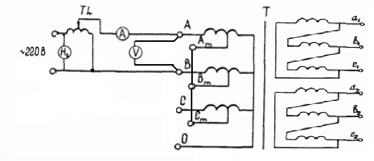

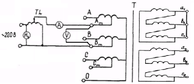

Fig. 7.3. Schemes for measuring the voltage and short circuit current to determine the Z T of the autotransformer (diagram and group of UN car compounds / d-0-11):
A - VN-CH winding (measurements in phase AV);
B - VN-NN 1 winding (measurements in phase AV);
B - CH-NN 1 winding (measurements in phase AV)
M - Winding SH-NN 1 (measurements in phase AV)
Deviation of the measured phase value of the short circuit resistance from the base value (%) is determined from the expression
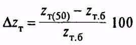
An assessment of the status of the test of the test transformer is compared to the obtained value Δz T with an extremely valid deviation of this parameter from the base value set by industry regulatory documents.
The maximum sensitivity in the measurement of voltage and short-circuit current is achieved by selecting pairs of windings located near the rod of the magnetic pipeline.
When testing, it is advisable to adhere to such a sequence of work to avoid frequent reinforcement of goodwear. For example, when testing triple transformers, it is recommended to measure in the following sequence: VN-CH, VN-NN, SN-NN, NN1-NN2.
The accuracy class of measuring instruments should be no less than 0.5.
The selection of current values \u200b\u200band short-circuit voltage can be performed as follows. The expected nominal value of the short circuit resistance (OM) from the expression is determined:
Where u is a linear rated voltage of the winding (VN, CH) transformer, kV;
U k - the short circuit voltage of the transformer,%;
I HOM - the rated current of the winding (VN, CH) of the transformer, and;
U HOM, U K - transformer passport details for a specific winding, specific branch.
The rated current of the transformer (A) is determined from the expression

where s HOM is the rated power of the transformer, kVA.
U nom - linear rated voltage of the transformer winding for a specific winding, concrete branch, kV;
The expected current in the experience of a short circuit can be performed as follows from the expression:
Where u is a linear voltage supplied to the winding of the transformer, kV;
Z k - a short circuit voltage of the transformer, Ohm;
The current in the blizzard for a specific measurement scheme can be determined from the expression:
Where i expectation is the expected CW current on the supply side of the voltage (HV), and;
K T is the transformation coefficient of the transformer of those windings on which experience is carried out.
Procedure for performing work:
To get acquainted with the passport of the transformer, write out Somme, U Nom, U to, I Mr. for all branches of all combinations of windings, write down the winding compound scheme, write down previously correct measurements.
Determine the expected current when measuring, for all necessary combinations of windings and branches.
Determine the expected twist current, for all necessary combinations of windings and branches.
Create a convenient table for recording parameters, example
|
RPN position | ||||||||||
In accordance with the expected current of the CW and the voltage level, select instruments for measurements.
Prepare a lathe, appliances with connecting wires, extension cables, two-housing cables (for connecting to inputs), twirling the required length and sections, hardware to install a blorest and connect to inputs.
Allow for work.
Displays a transformer from all sides, including neutral.
Make measurements in the following sequence: VN-CH, VN-NN 1, VN-NN 2, SNN 1, SNN 2, NN 1 - NN 2.
The Z table is not the desired, because Defined from linear values \u200b\u200bof currents and voltages. Z K is determined from the expressions of recalculation of linear values \u200b\u200bZ to phase z to which are indicated above.
Page 13 of 19
12. Measurement of the resistance of the loop phase - zero protective conductor
Periodically and before commissioning objects receiving energy from networks with grounded neutralThis is checked for the conformity of the network of reassembling the requirements of PUE in relation to ensuring the disabling of the emergency section. Reliable shutdown of the damaged area is considered to be provided if the current is single-phase short / k corresponds to the condition / K\u003e to / n
where / nomes - the rated current of the fuse rate or current of the fuse setpoint of the circuit breaker; K-coefficient depending on the type of protection.
To determine the current of a single-phase KZ, it is necessary to measure the impedance of a chain of a single-phase closure on the housing or zero protective conductor. This can be done in several ways.
Fig. 37. The scheme of the IPZ-2M apparatus
1.2 - Grounding points to verify the status of fuses
Fig. 36. Scheme of measuring the resistance of the chain of the phase - zero by the method of ammeter-voltmeter:
Measurement of the total resistance of the loop of the phase is a zero protective conductor in the ammeter - voltmeter method. This method is used when the test equipment is disconnected. Measurement is performed by alternating current reduced voltage from a sufficient power transformer. A scheme is assembled for measurement (Fig. 36), and then artificial closure is made of one of the phase wires on the electrical equipment housing. After supplying the voltage to the measuring circuit, the current / voltage U is measured. The current value must be 10-20 A.
The phase chain resistance is a zero protective conductor is determined by the formula Zn \u003d UII.
Single-phase CW / K current is determined by the formula ![]()
where s / f is the phase voltage of the network, V.
Measuring resistance loop phase zero Protective conductor device type IPZ-2M. The device measures directly a single-phase closure current on the housing in the networks 380/220 V. The device attached to the phase wire and to the object of the test object, performs a short-term (about 0.05 seconds) of the KZ between, phase wire and the subject of the subject object, which makes this method Practically secure. The diagram of the device is shown in Fig. 37.
To ensure short-term closer to the loop under the device, there are two contacts of a special design, held by latches; Camping - in open and opening - in a closed position.
The heavy pendulum M translated into the upper position, with a subsequent free fall, it is released first a latch of the closing contact, and then "the discontinuing, due to which there is a short-term closure of the hinges on resistors with a resistance of 3 or 0.08 ohms (R3 and R4). When the voltage drops appears on these resistors, the capacitor with through a Germany diode VD is charged to a voltage proportional to the current flowing through the formed chain. When you press the SN button, the capacitor with discharged to the microammeter with a sequentially turned on the resistor. The microamer arrow is installed on the division of the scale corresponding to the measured current. The method of assessing the resistance of the loop of the phase zero using the IPZ-2M apparatus is reduced to the comparison of the measurement results with the value of the protection current. 
Fig. 38. Scheme of the resistance meter loop phase-zero type ITC-1
Other devices are known for measuring the resistance of the loop of the phase - zero. The main advantage of ITC-1 devices is that when measuring does not need to disconnect the electrical receivers, if applied to attach the device to the phase wire, the connecting conductor with a dipstick or spring clip equipped with insulating grippers. The device is simple and reliable in operation. The concept of the instrument is shown in Fig. 38.
If you put the S switch to position, then after connecting the device to the phase wire wire and the housing of the enlarged equipment and turn on the circuit breaker, and from the secondary winding of the transformer T and rectifier V, the SZ capacitor is charged via the SW switch contact in each positive half-period, the VT1 transistor and The VT2 transistor opens. When switching s to the position and (measurement), the SZ condenser into the nearest positive half-period is discharged to the thyristor of the thyristor VI, the latter is opened, a single-phase short-circuit current currently passes (only before the negative half-period, and then the thyristor is closed and the next positive half-period is not It will open, since the capacitor of the SZ is discharged, and its charge chain is open). The voltage of the KZ on the C4 condenser after closing the thyristor is fixed by the arrow device, taped in
Omah (or in amperes). The C4 capacitor charges very slowly, and after recording the readings, the switch set to (reset) to prepare the device to new dimensions. To avoid errors due to the unequal value of the network voltage, before measuring the instrument adjusts the actual voltage of the network using a variable resistor R11 at the position to "voltage control" of the switch S. If the voltage fluctuates and there is a concern that it may change between the minds "voltage control "And" Measurement ", then the processes of control and measurement are recommended to be repeated before the coincidence of the results. The measurement limits of the instrument from 0.05 to 3 ohms, the error is not more than 10%. The procedure for measuring the resistance of the loop of the phase-zero device ITC-1 is as follows:
Corp case; Connect the device with one wire to the phase wire of the electrical installation, and to the other to the body of the entered electrical receipt; include circuit breaker; Install the switch to the position of the zero setting potentiometer and the handle set the arrow at the K, set the switch knob to the (reset) position; rotate the handle to the position and record the testing of the device; Turn off the circuit breaker; The knob of the switch put in position O.
Measuring the resistance of the loop of the phase -Close protective conductor with a M-417 type device.
The M-417 type device is designed to control the resistance of the loop of the phase - zero protective conductor without turning off the power supply of the current in electrical installations 380 in the 50 Hz frequency with a grounded neutral. With it, the voltage drop is measured, proportional to the resistance of the loop of the phase - zero protective conductor, so the scale of the instrument is marked in Oma. The device provides an automatic shutdown of the measuring circuit from the controlled network for no more than 0.3 s, the alarm system when the voltage object appears exceeding the 36 V (resistance of the phase loop - zero is greater than 2 ohms), the lighting chain break signaling; The measurement limits of the instrument 0.1-2 ohms.
The main error of the device according to the plant is ± 10% of the length of the working part of the scale (from 0.1 to 0.6 ohms). The M-417 device approximately takes into account the inductance of the loop "Phase - zero", and therefore the measurement error can be up to ± 17%.
In the Latvian power system, a single-phase transmission procedure is used, designed to work on 0.4 kV ppm with a current of a single-phase KZ to 1000 A (Fig. 39). Phase and neutral wires of the line of the climb are turned on the circuit breaker q in 0.06 seconds from the relay to the circuit breaker turns off. Time to disconnect the circuit breaker. Less than the time of the fuses of fuses. Time shutter speed is set by a C1 condenser. 
Fig. 39. Diagram of the device for measuring the resistance of the phase zero chain, developed by Latvglavenergo
The start button and the auxiliary contact K1 do not allow re-turning on the circuit breaker Q. The voltage on the C2 condenser depends on the CW current. 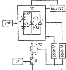
Fig. 40. Structural scheme IPZ-2T:
VT1-VT3- Thyristors; ZT - thyristor closer; E03VTI-B03VT2 - blocks of a single trigger of a thyristor.
GT1-TK; IF - phase meter; - CZ meter; TA - Measuring current converter; R - Calibrated active resistance
The ISM CW ISM current meter consists of a power part, high-aligned voltmeter, control and power blocks. The measuring circuit is connected to the clamping of the power part containing a powerful resistor, along which a single-phase shortcutron current flows when the control unit is triggered. The voltage drop varies with a high-resistant voltmeter, the scale of which is marked in amperes. The power supply consists of a rectifying bridge and stabilion transformer.
Measurement of the resistance of the loop of the phase is a zero protective conductor with a thyristor device of the IPZ-2T.
The IPZ-2T portable device (Fig. 40) is designed to test the loop of the phase-zero in the networks 380/220 V with a grounded neutral method of direct measurement in the current loop close to the effective values \u200b\u200bof the CW current. When using this device, the measurement error is practically excluded, the nonlinearity of the resistance of the loop of the phase is zero.
The front panel of the device contains input clamps, ammeter, phase shift meter with light indication, mode switch, potentiometer. In a special compartment, thyristors, a measuring shunt, fuse, a power supply of phase shift angle meter and a current transducer is placed.
The measuring current of the KZ is passed through the devices the flow of two semideiodes. During this time, the values \u200b\u200bof the current and phase angle in the phase circuit are zero.
The first half-period of the CW current is passed by the VT1 thyurist, the E03VT1 block. The inclusion of the power thyristor VT2 in the second half-period of the current of the CW and thyristor 1 / TK, which includes the phase shift measuring devices, is made by the units, respectively, the E03VT2 and E03VT3, for which the signals come from the transducer of the current transducer that issuing pulses when the CZ current transitions through zero.
The current of the KZ in the loop is determined according to diagrams based on the ammeter reading. The technical characteristics of the IPZ-2G device is shown below:
Supply voltage, 220
Duration KZ, from 0.02
The maximum value of the phase angle in the phase circuit is zero, hail 90
Current measurement error,%, no more than, ± 5
Phase angle measurement error,%, ± 2
Dimensions, mm 415x284 x
; X 185.
Mass (included), kg, not more than 13
Measuring instrument of CZ loops Phase - zero protective conductor of the IPZ-T type.
A single-phase short-circuit current meter of the IPZ-T type is designed to verify the correct set of settings for the maximum current protection against single-phase closures on Earth in networks with a grounded neutral 380/220 V. It has the following key characteristics:
Supply voltage, 220 + 22
The limits of measuring the currents of the KZ, and:
The first from 250 to 2500
second from 50 to 2e0
Phase angle measurement limits in current circuit
KZ, hail from 10 to 80
Dimensions, mm 390 x 250x160
Mass, kg 10
The operation of the device of the IPZ-T is based on a CW current measurement with an automatic restriction of its flow (not more than 0.01 s).
Depending on the selected operation mode, the current flow time or the voltage drop on the measuring shunt is remembered as a voltage on the appropriate capacitors and are read through the directional instrument. To eliminate the effect of the aperiodic component of the CW Current, the shift angle of the steady value of the current φ is measured in relation to the voltage, and then a re-KZ is performed at the time corresponding to the measured corner "p. The scale of the device and the leb will be separated into the values \u200b\u200bof T, where the angle T \u003d 50f / 180 divisions. This angle is measured with a boron.
When checking settles circuit breakers Maximum current protection are possible cases of disconnecting these switches at CW currents, more than 8-10 times higher than the setpoint. The CW COP is interrupted by a ipz-t thyristor, and not a circuit breaker. The value of the CW current in this case is stored in the "memory" of the device and can be determined by the direction of the switch when the circuit breaker is re-turned on. Disabling the circuit breaker indicates the correctness of the stink of the switch from the point of view of protection against single-phase KZ.
When working with the meter, it is necessary to comply with a number of security measures. Persons who have the III qualifying group are allowed to work with the meter. Connecting the phase wire is performed in the absence of voltage on the network. In the production of measurements, the operator must be on the rubber rug.
Code Current Cover Phase Current - Zero Protective Conductor Type IPZ-C.
The Digital Meter of the IPZ-C type is designed to determine the current of a single-phase KZ in industrial networks 380/220 V with a grounded neutral needed when choosing fusible inserts
and settings for automatic protective devices.
The device has the following specifications:
Error at all measurement limits,%, not more than ± 5
The time of the current of the same name of a single-phase KZ created by the device, MS is not more than 14
Limits of measuring the current of the CW, ka:
The first from0.1 to 2
second from 1 to 20
The device maintains specifications:
When developing on failure, h at least 500
under service life, not more than 5 years
When working in the following climatic conditions:
air temperature, ° C is not lower than -10,
Not higher than +45
Relative humidity,% (at a temperature of +20 ° C), 95
The mass of the device, kg not more than 10
The meter consists of three main blocks: power, measuring and nutrition. The measurement of the CW current occurs in two stages. The first definition angle of the steady current value in relation to the voltage is determined, the CW current is measured on the second.
The design of the device ensures the safety of working personnel. All items electrical circuit The device is concluded in the casing preventing the possibility of touching parts under voltage. The device has a device that turns it off in case of malfunction of the current conductors. At the same time, when operating the device, it is necessary to comply with a number of electrical safety requirements, namely:
The adjusters using the device must have a qualification group not lower than III;
The case of the device must be reset during operation; Working with the device should be made in dielectric gloves and tool with insulating handles.
Other types of devices were developed for measuring the resistance of the loop of the phase - zero-protective conductor. It is known that when measuring the resistance of the loop of the phase, the zero protective conductor with typical devices under the operating voltage of the network on the measurement result, the operational vibrations of the voltage have significant impact. At the same time, the increase in the current of the KZ to several hundred amps, which is necessary to reduce the effect of voltage operational oscillations, is possible only under the condition of the maximum reduction in the duration of the current passage.
In the Rostov Institute of Rail Transport Engineers, a phase loop measurement was developed for measuring the phase loop - zero protective conductor, equipped with a thyristor closer, which, tooling the CC current of about 200 A, limits its duration by one period than the measurement security is ensured.
In some cases, checking out the disabling of the network of the network is performed by closing the case when operating the network in a normal circuit with full voltage. This method cannot be recognized correct, since, with malfunction or small conductivity, the grounding circuit on grounded electrical equipment can occur dangerous tension. The use of this method is completely unacceptable in explosion and fire-hazardous premises.
In some cases, for measuring the resistance of the loop of the phase - the zero protective conductor use the MS-08 device. It should be borne in mind that this device is not suitable for measuring the resistance of chains containing reactive resistance. Therefore, it is used to measure the resistance of the phase chain - zero protective conductor, which usually resistance 0.45-1 ohms (or cos φ "0.9 - \u003d - 0.7) can be allowed upon receipt of a stock in the zn value of about 30% .


