The choice of the mode of operation of the electrical installations, which, according to the terms of the electrical safety, are divided by PUE on electrical installations with a voltage to 1 kV and above 1 kV, should be carried out taking into account the uninterrupted power supply of electricity receivers, system efficiency, network security, security loss minima, the possibility of limiting switching overvoltages, Reducing electromagnetic influences on the communication lines, selectivity of the relay protection and simplicity of its implementation, the ability to hold the damaged line in the work, preventing development in the network of ferroresonance phenomena, the possibility of further development of the system without significant reconstruction, etc.
The electrical networks of Russia adopted the following modes of neutral operation:
- isolated neutral (small capacitive shorts of closures on the ground; voltage of 6 35 kV and 0.4 kV);
- compensated neutral (certain exceeding the values \u200b\u200bof capacitive currents; voltages 6 35 kV);
- effective (deaf) grounded neutral (large ground closures; voltage 110 kV; 0.4 kV);
Characteristics of the mode of isolated neutral
Dignity |
disadvantages |
1. The ability to work with OZZ for a limited time before taking measures to troublewar disconnecting the damaged element |
1. High likelihood of the most dangerous arcs intermittent OZZ |
2. Additional equipment and grounding cost neutrals are required. |
2. High probability of secondary samples of isolation and transition OZZ in double and multi-seat closures due to overvoltages up to 3.5 UF machines for arc closures |
3. The ability of the arc and self-destruction of the OZZ part |
3. Significant (several times) an increase in the current current value at the place of damage to arc alternating OZB due to the free components of the transition process |
4. Safety of prolonged exposure to overvoltages arising in transition modes of OZZ, for elements with normal insulation |
4. The possibility of significant damage to the electric vehicles current at the place of damage, primarily, with arcs intermittent OZZ |
5. Simple (in most cases) solving the problem of protection and selective alarm of sustainable OZZ |
5. The possibility of ferroresonance processes on the network and TN damage |
6. High degree of danger for humans and animals located near Ozz |
|
7. Restrictions on the magnitude of the development of the network |
|
8. High degree of power supply under arc OZZ |
|
|
Characteristics of the resonant grounding of neutral (compensated neutral) |
|
Dignity |
disadvantages |
1. Ability to work with OZZ to take measures to troublewar disconnecting the damaged element |
1. Additional neutral grounding costs through DGR and devices for automatic compensation setting |
2. Reducing the current in the place of damage (with a resonant setting of DGP, the residual current contains only noncompensated active components and higher harmonics) |
2. Difficulties with solving the problem of sewn and selective alarm OZZ |
3. A significant reduction in the rate of recovery of the voltage on the damaged phase after the ozb arc cliff. |
3. The possibility of intermittent arc ozz, accompanied by overvoltage in intact phases to 2.5 UI, Max |
- high resistance and low-level neutral grounding (voltage 6, 10 kV).
4. High likelihood (taking into account paragraphs. 2 and 3) of the downce and self-destruction of the most of the OZB (with limited values \u200b\u200bof the residual current at the place of damage). |
4. Increase the likelihood of arc intermittent 033 and maximum overvoltage on intact phases to (2.6-3-3) UFTs when compensation disorders |
5. Almost eliminated the possibility of arcs alternating OZZ |
5. Possibility (taking into account paragraphs. 3 and 4) secondary breakdowns at the network points with weakened insulation |
6. Reducing the multiplicity of overvoltages on intact phases compared to isolated neutral (to 2.5m values \u200b\u200bat the first test of insulation or arc discontinuous OZZ |
6. The inability to compensate (without the use of special devices) in the place of damage is the active component and higher harmonics |
7. Safety of prolonged exposure to overvoltages in the established and transitional OZZ modes for elements with normal isolation. |
7. Increase (taking into account paragraph 6) of the residual current at the place of damage with the growth of the total capacitive current of the LM network |
8. The possibility of ferroresonance processes on the network is eliminated. |
8. Restrictions (taking into account clause 7) on network development |
9. Reducing the effect of arc ozb on the communication line |
|
|
Characteristics of high-wing neutral grounding mode |
|
Dignity |
disadvantages |
1. Ability to work with OZZ to take measures to disabag the damaged element (with limited closure current values \u200b\u200bat the damage place) |
|
2. The ability to scap the arc and self-destruction of the part of OZB (with limited values \u200b\u200bof the OZZ current in the place of damage) |
2. Increased current in the place of damage |
3. Practically excludes the possibility of arc moving OZZ |
3. The possibility of intermittent arc ozz, accompanied by overvoltage on intact phases to 2.5 C ,.nch |
4. Reducing the multiplicity of overvoltages on intact phases compared to an isolated neutral (to the values \u200b\u200bof 2.5 C\u003e nom during the first test of insulation or arc intermittent OZB) |
4. Possibility (including p. 3) secondary breakdowns at the network points with weakened insulation |
5. Safety of prolonged exposure to overvoltages in transition modes OZZ for elements with normal insulation |
5. Restrictions on the development of the network largest |
6. Practically eliminates the possibility of ferroresonance processes in the network |
6. Weighing arc harvesting conditions in the place of damage compared to networks working with an isolated neutral or with a capacitance current compensation |
7. A simple solution to the problem of protection and alarm of sustainable OZZ |
7. The high power of the ground resistor (tens of kilowatts) and problems with ensuring its thermal resistance during sustainable OZZ |
Characteristics of the low-voltage grounding of neutrals through a resistor
Dignity |
disadvantages |
1. Practically eliminates the possibility of further development of damage, for example, transition 033 to double-circuit on earth or interphasis KZ (with a quick disconnection of the damaged element) |
1. Additional grounding cost neutral network via resistor |
2. Simple solution to the problem of protection against OZZ |
2. The inability to work with OZZ |
3. Fully eliminated the possibility of arc intermittent OZZ (with sufficient suppression of the imposed value of the imposed active current) |
3. Increasing the number of hardening equipment and lines due to short-term shutdown transitions (with arc neutral grounding modes) Insulation breakdowns in full (completed) tributes |
4. The duration of the impact on the insulation of the elements of the overvoltage network on the intact phases in the transition modes of OZZ |
4. Ability to increase in some cases the volume of equipment damage (due to an increase in the OZZ current) |
5. The possibility of ferroresonance processes on the network is excluded. |
5. The possibility of arc intermittent ozz with insufficient values \u200b\u200bof the applied active current |
6. The likelihood of lesion of people or animals of OZZ current is reduced in place of damage. |
6. The possibility of secondary breakdowns at diluted with isolation due to overvoltages on intact phases (when the insulation is first trigue to 2.5 UF, before turning off the damaged element |
7. Increasing the number of network switches |
With the deaf grounding neutral, the closure of one phase on the ground is a single-phase KZ characterized by a high current. Phase voltage relative to the land at the same time not higher than the phase nominal; Interrogated arcs are excluded. Single-phase CWs are automatically disconnected. Disabling leads to interruptions in power supply consumers.
Another disadvantage of the deaf neutral ground is a significant complication and appreciation of grounding devices. The latter is due to the fact that for a system with a large circuit current to ground PUE, the maximum resistance of the grounding circuit 0.5 ohms is allowed, so the number of grounding electrodes should be significant. Due to the significant current of a single-phase KZ, which can be more than a current of three-phase shortcuts, not all transformer neutrals are deaf.
Based on the consideration of the advantages and disadvantages of various operating modes of neutral, satisfying in one degree or another, the requirements for grounding neutral can be drawn by the following practical conclusions.
In the power supply systems, 6.10.20 and 35 kV, an isolated neutral is used if the capacitive currents do not exceed with single-phase closures on the land of the values \u200b\u200bestablished by Pue, otherwise neutrals are used, grounded through the arcs, compensating for the capacitive circuit current to the Earth. At 6 and 10 kV voltages, the neutral of the generators are usually ground through active resistance. In systems of voltage 110, 220 kV and above, an effectively grounded neutral is used. Plug-free neutral at voltages up to 1 kV are used in a four-wire system with a voltage of 380/220 V, the advantage of which is the ability to power from one network of power and lighting loads, as well as in three-wire systems direct current. In three-phase systems with voltage 380 and 220 V, both isolated and deaf-free neutral. With increased security requirements (for mobile installations, peat developments, mines), electrical installations with an isolated neutral or isolated single-phase current source output, if their voltage is below 1 kV, and in the electrical installations of the DC, the same voltage isolate the midpoint.
The decision on the choice of the mode of operation of the neutral of electrical installations should be based on PUE recommendations.
Production, Conversion, Transportation, Distribution and Consumption electrical Energy It is carried out according to a symmetric three-phase wire system. The symmetry of the system is achieved by the equality of phase and linear stresses, uniform loading of all phases by current, the same shift of the phases of stresses and currents.
However, in the process of operation, a violation of the symmetry of a three-phase system is inevitable, which can be caused by: loss of wires, isolation breakdown, overlapping for foreign objects, non-infraction of the phases of switching devices, etc.
In any case, the notymmetry leads to the appearance of reverse and zero sequence currents, as well as the aperiodic component of currents that can be dangerous for the safety of the equipment. Therefore, asymmetry should be eliminated as quickly as possible. On the speed of relay protection in case of incomplete-phase modes, the mode of operation of the network neutral has a significant effect.
There are several operating modes of neutral:
- isolated
- plukhozhedoy
- effectively grounded.
Each mode has its advantages and disadvantages. In networks voltage up to 35 kV inclusive used neutral. This means that the average point of the transformer winding point is not connected to the Earth.
A single-phase closure with such a power supply system to the Earth does not lead to an emergency disconnection of the damaged line, since the current of the earth closure is quite insignificant, its value is due only to the capacity of two intact phases relative to the Earth. The current of single-phase closure on the Earth, in networks up to 35 kV is not able to maintain the burning of the arc.
With a metallic closure of one phase ("Full Earth"), the voltage on the other two increases to the linear, but the power supply of consumers is saved along the two remaining phases. For the preservation of transformers with such modes of operation, its neutral isolation is performed on the voltage class of the corresponding insulation of linear inputs.
With significant capacitive currents of lines of up to 35 kV, exhausting coils connected to the neutral transformers are used. The arc harvesting is ensured by the inductance of the coil, which compensates for the capacitive circuit current to the Earth.
The power supply system with effectively grounded neutral is the network in which part of the neutral windings of power transformers are grounded. Single-phase short circuit, in such networks, leads to a disconnection of a damaged area.
Current short circuit passes from the place of damage to the nearest grounded neutrals Transformers on the ground, distributing in accordance with the resistance of the loop phase - zero. To transformers, the neutral of which is not grounded, the short circuit current (hereinafter - KZ) does not proceed.
Considering the fact that all kinds of damage in electrical networks, 80% of damage falls on single-phase KZ, and the fact that close single-phase KZ. Have significant currents of currents, their influence is trying to limit.
To do this, part of neutrals on the network are left uncontrolled, thereby increasing the resistance of the loop of the closure and, limiting single-phase Toki. Kz. The total balance of grounded and ungrounded neutrals is calculated based on the conditions of the selective operation of the RZ devices and the limiting current of the CW.
In addition, an important condition when choosing a grounding point, is the condition for limiting overvoltage on neutral windings in asymmetric damage. On force equipment, the neutral insulation class is usually taken on one voltage class below the nominal voltage of the VN winding. This practice saves on isolation and equipment dimensions, which gives a high economic effect.
However, on the other hand, the reduced level of isolation neutral leads to the need to use equipment that would limit the overvoltage and currents in the zero output. Overvoltage limiters can be used as protection against short-term overvoltages, current-limiting reactors and capacitors are used to limit currents.
In the deaf grounding mode, networks with a household consumer operate. With this mode of operation neutral, the average point of the NN of the transformer is attached to the grounding circuit. In distribution panels of residential buildings, the plates housing also joins the grounding circuit.
So, in each apartment or house "comes" two wires: phase and zero - providing consumers with a voltage of 220 V. When damaged isolation of the phase wire, and touching it to grounded structures, immediately disabling the damaged area of \u200b\u200bthe network occurs. Concrete walls and floors in apartment housesAlso have the potential of the Earth.
The CW current has sufficient values \u200b\u200bfor the triggering of protective switching equipment. IN latelyTo enhance the level of electrical safety, in addition to the working zero, a protective ground is created in residential premises, which connects to the electrical appliances enclosures. The wire protective grounding In the shield also joins grounded structures.
It should be noted that the autotransformers of any class of voltage always work with a deaf-free neutral. The insulation of the CH winding of the autotransformer is made on the basis of the value of the standard power, which is less nominal, and therefore the level of isolation reduced. In this, strictly speaking, the economic profitability of the autotransformer in front of the transformer is.
With incomplete-phase switching of autotransformers, hazardous overvoltages arise in the electromagnetic system, which can be limited to a deaf grounding of zero output.
Based on the foregoing, it can be concluded that the neutral operation mode has a significant impact on the reliability of power supply and the mode of operation of the power system as a whole.
Neutral (neutral points) electrical installations are called general points of phases of the windings of generators and transformers connected in the star. Neutral can be isolated from the ground, connected to the ground through reactive resistance, as well as directly grounded. The type of communication of neutrals with the Earth is determined by the safety of electrical installations, the reliability of power supply consumers and efficiency.
Depending on the neutral mode, the electrical networks are divided into four groups:
Networks with ungrounded (isolated) neutrals;
Networks with resonant-grounded (compensated) neutrals;
Networks with efficiently grounded neutrals;
Networks with deaf-andled neutrals.
but) Networks with neutral isolated.
They are three-wire networks alternating currentIn which the source, the power line and receivers are normally connected to the Earth. Due to the imperfection of the insulation of conductors, some leakage of currents on the ground occur, which can be conventionally displayed active resistances Isolation of each phase ,, (Fig. 1, a). In addition, the conductors of each phase and land can be viewed as condensers, which correspond to capacitive resistance, and containers ,,. The corresponding resistance is connected by the star, the neutral point is land. Capacitive currents passing on earth resistances create voltage drops, i.e. There are phase voltages of wires relative to the Earth: ,,
In the normal mode of voltage operation,, symmetrical and equal to the phase voltage of the consumer, and the capacitive currents of the phases are also symmetrical. With this capacitive phase current
![]() (1)
(1)
where - the phase capacity relative to the Earth. The geometric sum of capacitive currents is 0 and therefore the current through the ground does not flow (Fig. 1, b):
![]()
In the event of a closure to the Earth, one of the phases of the network, for example phase A, the voltage of this phase relative to the Earth becomes zero (the surface of the Earth at the point of damage takes the potential of this phase), and the voltages of intact phases (B and C) are increasing relative to the ground at times, t .. become equal linear stresses (Fig.2)
Accordingly, the capacitive currents of these phases are also increasing at times. Single-phase closure for Earth in the place of damage is determined by expression
![]() (2)
(2)
those. increases 3 times compared to capacitive current in normal mode
According to (3), the current depends on the voltage of the network, its frequency ω and the phase container relative to the Earth, which depends mainly on the design of the network line and their length. Approximately current, and, can be determined by the following formulas:
for VL ![]() ,
,
where - Linear network voltages, kV
l.- Length of electrically related areas of the network of this voltage, km.
From the vector diagram, it can be seen that with single-phase closures on the ground in networks with an isolated neutral, the linear voltage triangle is not distorted, so consumers included on linear voltage continue to work normally. At the same time, it should be noted that during the operation of a network with a closed-to-ground phase becomes more likely to damage the insulation of another phase and the occurrence of interphasis shorts through the Earth. In this regard, in networks with isolated neutral, special signaling devices that inform the occurrence of single-phase closures on the ground are required.
According to PUE, the permissible duration of working with a grounded phase in most cases should not exceed 2 hours.
Due to the fact that with single-phase closures on Earth, the phase voltages of intact phases increase to the level of linear, insulation in such networks should be calculated on linear voltages. This limits the area of \u200b\u200buse of such a mode of operation neutral with voltage with voltage not higher than 35 square meters.
The operation of the network with an isolated neutral applies and in networks with the UB≤1 sq. These networks provide a high level of electrical safety and should be applied to mobile installations, peat developments and coal mines.
b) Networks with resonant - grounded neutrals .
In the event that the network with an isolated neutral has a relatively large capacitive circuit current to the Earth, namely
at 6kv IK ≥ 30a,
at 10kv Ik ≥ 20a,
at 20kv IK ≥ 15a,
at 35 kV IK ≥ 10a,
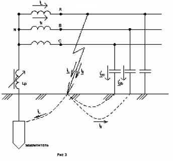
it is possible that the appearance of dangerous intermittent KZ to Earth is possible. To avoid this, according to PUU, measures should be taken to compensate for the capacitive current of the CW. Compensation is carried out with the help of adjustable extinguishing reactors (inductance coils), which are included in the neutral of transformers and are configured in almost resonance with the capacitive network resistance.
In normal mode, the current through the reactor is almost equal to zero. With a single-phase short circuit, the reactor is under the phase voltage of the network and through the place of closure to the ground flows along with the capacitive current of the IK also an inductive current of the reactor I L. Since inductive and capacitive currents are opposed to phase, then they compensate for each other in the ground closure. If i l \u003d i c (resonance), then there will be no flow to leak through the place of closure to earth. Thanks to this, the arc in the place of damage does not occur and eliminate associated with it dangerous consequences. (Fig. 3)
in) Networks with efficiently grounded neutrals .
 In the networks of 110 kV and higher in the selection of a neutral grounding method, the factor of the isolation value is a factor. Here, an effective grounding of neutral is used here, in which during a single-phase short circuit (OKS), the voltage on intact phases relative to the Earth is ≈0.8 in normal operation. This is the main advantage of such a neutral grounding method (Fig. 4). One of the disadvantages is a significant current of the OKS, which, with a large number of grounded transformer neutrals, may exceed the current of the three-phase KZ. To reduce the OKS currents, use if it is possible and efficiently, the leveling of some transformers neutrals in 110-20 kV networks.
d) Networks with deaf-andled neutrals .
Industrial enterprises are widely used by four-wire three-phase networks Voltage 380/220 V. Fig. 5 shows a diagram of such a network with a deaf-free neutral, when the secondary winding is connected to the star, and the neutral point directly (deaf) is connected to the grounding device.
![]()
Motors D1 and D2 are connected to the network phases and are powered with a linear voltage U \u003d 380 V, and the lamps l are connected between phase and neutral wires and feed on the phase voltage \u003d 220 V. The N-wire performs two functions: the working wire to which Connect single-phase receivers by 220 V, and the wire of the reinforcement, i.e. It is deliberately attached to the metal hulls of electrical installations, not normally under voltage. If you have a reasanced of the insulation test, the engine winding on the housing will cause a high short circuit current and quick trigger protection ( circuit breaker QF) With the engine disconnection from the network. In the absence of reassembling the engine of the engine D2, the insulation damage to its winding will cause dangerous potential on the housing relative to the Earth.
With a single-phase KZ, the voltage on the intact phases relative to the Earth does not increase and therefore the insulation can be calculated on the phase, and not on linear voltage.
Thus, in electrical networks, the following neutral regimes are taken: a network of 0.66-35 kV, depending on the value of the capacitive current of the ground, the ground is operated either with an isolated neutral, or with a resonant-grounded neutral; network 380/220 V- with deaf-market neutral; 110 kV networks and above, with efficiently grounded neutral.
The electrical installation neutral is called the common point of the generator winding or transformer connected to the star. The neutral point can be isolated or grounded. This largely determines the conditions of the electrical installation, the level of insulation, short circuit currents, the values \u200b\u200bof the overvoltage voltage.
By neutral mode, electrical networks and electrical installations are divided into four groups:
Networks with neutrals;
Networks with resonant-grounded neutrals;
Networks with efficiently grounded neutrals;
Networks with deaf-andled neutrals.
The electrical network with an efficiently grounded neutral is called a three-phase electrical network with a voltage of above 1 kV, in which the fault coefficient on the ground does not exceed 1.4.
Camping coefficient On the ground in a three-phase electrical network is determined by the ratio of the potential difference between the intact phase and the ground at the point of closure to the land of another or two other phases to the potential difference between the phase and the ground at this point to the closure.
Plug-free neutral A transformer neutral is called or a generator attached to a grounding device directly or through a small resistance (for example, through current transformers).
An isolated neutral is called a transformer or generator neutral, which is not attached to the grounding device or connected to it through the alarm, measurement, protection devices, and their similar devices that have large resistance.
The ground is called a deliberate electrical connection of any point of the network, electrical installation or equipment with a grounding device.
Networks with insulated neutrals and networks with resonant-grounded neutrals include networks of voltage 3, 6, 10, 35kV.
The connection of the equipment windings with a triangle and a star with an isolated neutral in networks create an isolated neutral network.
Accordingly, in networks with insulated neutrals in normal mode, the phase voltage relative to the Earth is symmetric. The capacitive component of network lines usually does not exceed 5a. In the event of a closure to the Earth, the voltage of the phases increases to a linear value. Taking into account the capacitive component of the current, the voltage of the damaged phase above zero, almost slightly less than the phase, if the closure passes through some transition resistance.
Therefore, with single-phase closures on Earth in networks with an isolated neutral, the voltage triangle is not distorted and consumers included on the interpasic voltage continue to work. It should be noted that the insulation of the phases must be calculated on the interpasal voltage. In electrical installations up to 35 kV, the cost of insulation allows some higher prices for the cost of the value of the main substation equipment, since it is not defining. At the same time, working with a phase-closed phase at one point is dangerous by closing at another network. Therefore, in networks with isolated neutral, constant insulation control and signaling about its damage are necessary.
The operation of the network with an isolated neutral is used at voltage up to 1kV. These networks provide a high level of electrical safety and are used for mobile installations, peat developments and mines. To protect against a breakdown of isolation between windings of higher and lower voltages in neutral or in each phase of the transformer, a punching fuse is installed.
If in the specified networks of the earth closure over the permissible norms, then to reduce the current in the networks, neutral grounding is used through the exhausting reactors is a network with resonant-grounded neutrals. The exhausting reactors L1 and L2 should be installed on nodal substations associated with a network compensated for at least three lines, in Figure 2.13, their location is shown. When compensating for generator voltage networks, reactors have a near generators.
Figure 2.13 - Connecting exhausting reactors in networks with resonant-grounded neutrals
When connecting extinguishing reactors through special transformers or transformers of their own power supplies commensurate with reactor power, it is necessary to take into account their mutual influence. This effect affects the reducing valid compensation current compared with the rated current due to the presence of a transformer winding resistance reactor.

where is the rated current of the exhausting reactor,
Voltage of the transformer
Rated power of the transformer.
Especially abruptly limiting the transformer winding is manifested when using the Y / Y compound scheme, neutral grounding is shown in Figure 2.14a. So with single-phase KZ to the ground, inductive resistance is about 10 times larger than with interpheses.
Therefore, the reactor is better to connect to the transformer with the Y / D scheme. But it should be borne in mind that it creates an additional load with single-phase short and leads to an increase in heating.
Permissible power of the reactor provided with [Email Protected]
![]() .
.
where is the maximum load power.
With permissible transformer overload reactor power
110kV networks and above refer to networks with effectively grounded neutral. In the choice of method of grounding neutral, the determining factor is the cost of isolation, the neutral ground scheme in Figure 2.14.
Figure 2.14 - Grounding neutrals in networks
a) with resonant - grounded, b) with effectively grounded
The use of effective neutral earth grounding with single-phase KZ creates a voltage in good phases of about 0.8 interphase in normal mode. This is the main advantage of such networks. Disadvantages of effective neutral grounding
1) With a single-phase KZ, a short-circuit circuit is formed through the ground and the neutral of the source with a low resistance, which creates large currents. To prevent consequences, high-speed relay protection is necessary. Since most of the single-phase KZs in such networks are self-configured, the use of automatic re-switching devices (APV) is effective.
2) To remove large values \u200b\u200bof the CW current values, it is necessary to build complex circuit breeding contours of distribution devices.
3) With a large number of grounded neutrals of transformers, a single-phase short-circuit current can exceed three-phase current. In this case, it applies to reduced it to 110-220kV neutrals.
Networks with deaf grounded neutral are performed on voltage up to 1000V. These are networks close to technological equipment, the requirements for the safety of which are high. Power supply of three-phase and single-phase receivers in these networks is performed simultaneously. To power single-phase receiver from zero deaf grounded point, a zero working conductor is used.


