Power measurement.In chains direct current Power can be measured using an ammeter and voltmeter, since P \u003d.UI. However, more accurately can be measured directly electrodynamic wattmeter(Fig. 10.3). It consists of a coil with a small resistance, included, as well as an ammeter, consistently and called current windingand movable coil with a large resistance included in parallel and called voltage winding.
The rotating moment of the wattmeter is proportional to the product of currents in the coils:
where I is a current in a fixed coil, almost equal to the current current; 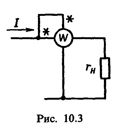 I U.
=
U./
r. U.
- current in the movable coil, T e. In the voltage winding; R U.
-
mobile coil chain resistance. Hence,
I U.
=
U./
r. U.
- current in the movable coil, T e. In the voltage winding; R U.
-
mobile coil chain resistance. Hence,
 (10.5)
where FROM -proportionality coefficient.
Thus, the rotating moment of the wattmeter is proportional to the power and its scale can be separated directly in watts or kilowatts.
For measuring active power in chains alternating current Apply wattmeters of an electrodynamic system.
Measurement of active power in single-phase chain. The electrodynamic wattmeter for measuring the active power in the alternating current single-phase circuit is also included in the dimension circuit in the DC circuit, i.e., according to the fig. 10.3. As the current I u in movable coil proportional to voltage U. and practically coincides with it in phase, and the current I in the fixed coil (current winding) is equal to the current current, the rotating moment of the wattmeter
where C is the proportionality coefficient.
So, the rotating moment of the wattmeter is proportional to the measured active power R,but opposing moment M. etc , proportional to the angle of rotation α of the movable coil (or arrows of the device). Therefore, the deviation of the arrow of the device is proportional to the measured power Rand, therefore, the wattmeter scale is graded in watts or kilowatts.
Clean winding clips and wattmeter voltage winding marked with asterisks and called generatorit should be included in the electrical circuit from the power supply.
Measuring active power in three-phase chain . Depending on the nature of the load and the three-phase circuit circuit, several methods of power measurement are used.
With a symmetrical load, the active power in the three-phase chain can be measured by measuring the power in one phase withusing the wattmeter included in the figures scheme. 10.4, a, b. After measuring the indication
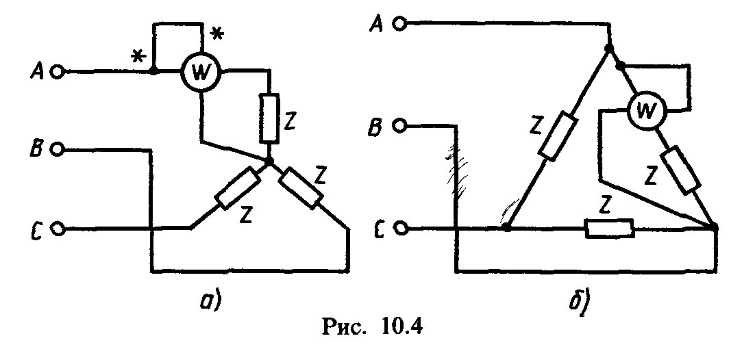
wattmera P. w. multiply at 3: * "
(10.7)
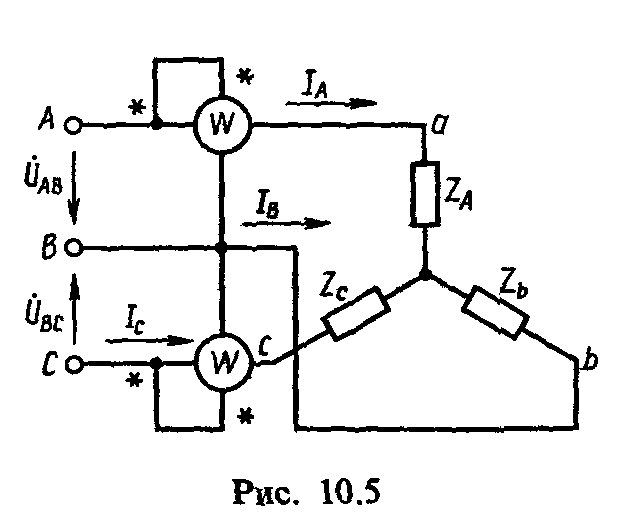
In a three-wire three-phase chain, both with symmetrical and asymmetric load and any method of connecting consumers, the active power can be measured using two wattmeters(Fig. 10.5). We show that the algebraic amount of the testimony of wattmeters in this case is equal to active power Rin a three-wire three-phase chain.
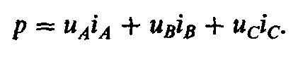
Instant power measured by the first wattmeter, P 1 \u003d U AB i a. Instant power measured by the second wattmeter, P 2 \u003d U Cb i c. The amount of instantaneous values \u200b\u200bof the capacity measured by two wattmeters, p \u003d.p. 1 + p. 2 = u. AB i. A. + u. CB. i. C. . .
If linear stresses and AU and u. CB. , which are connected by winding voltage wattmeters, express through phase voltages U AB = u a - u b ; u. cB. = and from - and in ,; that p \u003d I. BUT i. A. - u. B. i. A. + u. c. i. c. - u. B. i. c. or p \u003d.u. A. i. A. + u. c. i. c. - I. in (i. A. + i. c). As in a three-wire three-phase chain i. A. + i. B. + i. C. = 0, tO I A. + i. C. = - i. B. , , and the final expression of the power measured by two wattmeters,
From this expression it follows that the total instantaneous power measured by two wattmeters is equal to the active power in the three-phase chain when the star is connected. Similar arguments can be repeated and to connect consumers with a triangle, having received the same end result.
The active power of the three-phase system, expressed through the active values \u200b\u200bof voltages and currents and measured according to the method of two wattmeters, is equal to
where R w. 1 and p W 2 - testimony of wattmeters.
When measuring the active power by the method of two wattmeters for the case of a symmetrical load I. BUT = I. IN = I. FROM = I. l. ; U. AC \u003d U. CB. = U. l. .
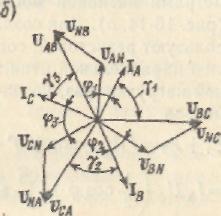
Figure 10.6 shows a vector diagram of currents and voltages that explains the measurements of the active power using
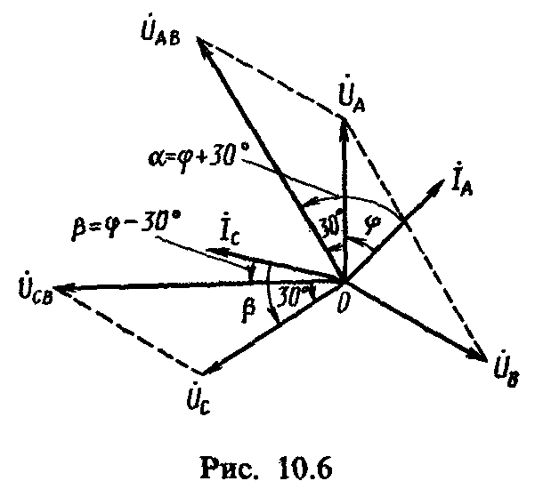
two wattmeters for symmetric load connected by the star. Since on the vector diagram angle α between U AB vectors and I. BUT equal to φ + 30 °, and the angle β between the vectors U Cb and I C is φ - 30 °, then the power of the three-phase system during symmetric load
If the phase shift angle φ< 60°, то, согласно (10.9), мощность, учитываемая ваттметрами, всегда положительна: R w1 = U. L i l cos (φ + 30 °) and p w. 2 = U. L i l cos (φ - 30 °). At φ \u003d 60 °, the power shown by the first wattmeter is zero: COS (60 ° + 30 °) \u003d 0. In this case, all power in the three-phase chain will be taken into account by the second wattmeter. With φ\u003e 60 °, the power accounted for by the first wattmeter becomes the negative and the total power of two wattmeters is calculated taking into account the sign of the power of the latter, as their algebraic amount.
Almost for the countdown of the negative power according to the wattmeter readings, it is necessary to change the current direction in the voltage winding, for which the current direction switch in the voltage winding is available on the wattmeter body, you need to switch from "+" to "-".
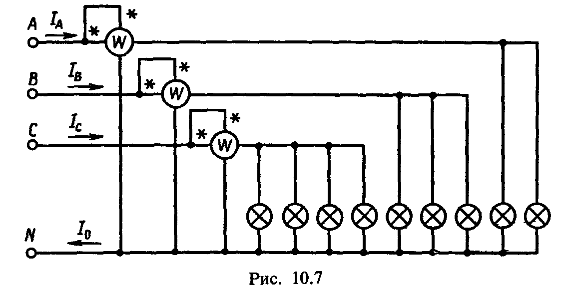
Measure the active power in a four-wire three-phase chain in the asymmetric load, you can three wattmeters (Fig. 10.7). Since in this case, each of the wattmeters measures the active power of the same phase, the power in the four-wire three-phase chain
where R BUT , R B. , P. C. - active phase capacities A, B, S.
Measurement of reactive power in a three-phase chain. The reactive power in a three-phase three-wire chain with a symmetric load can be determined by the difference in the readings of the wattmeters (see Fig. 10.5):
where does the reactive power come from
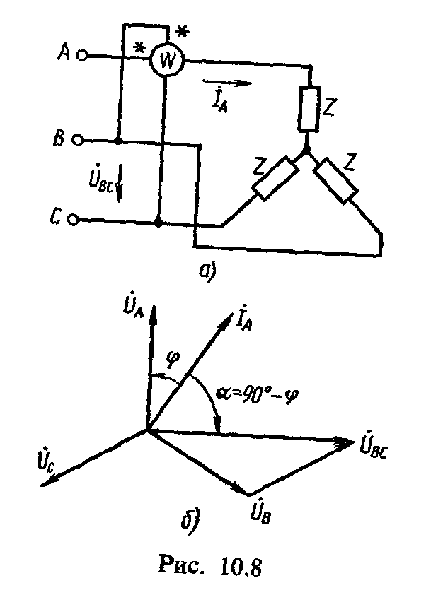
The reactive power in the three-wire three-phase chain during the Symmetric load can be measured with one wattmeter (Fig. 10.8, but), and the current winding of the wattmeter is included in the linear wire BUT,a voltage winding - on linear voltage U. BC. (i.e. on "someone else's" voltage). From the vector diagram (Fig. 10.8.6) it can be seen that the shift of the phases between the current I A and tension U. BC. it is α \u003d 90 ° - φ. Then the testimony of the wattmeter 4
To calculate the reactive power of a three-phase three-wire chain with a symmetrical load, you need to multiply the wattmeter to  :
:
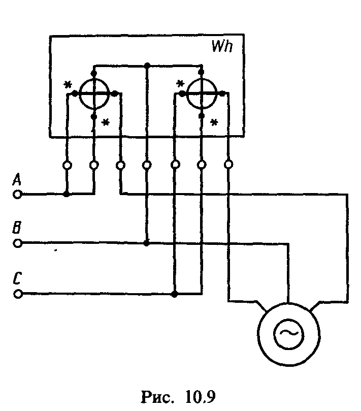
Measurement of energy in alternating current circuits. In alternating current circuits, single-phase and three-phase serve countersinduction system. To measure the active energy in single-phase and three-phase circuits, single-phase meters are included according to schemes similar to the inclusion schemes of wattmeters (see Fig. 10.3 and 10.5). In three-wire three-phase circuits for measuring the active energy, two-element combining measuring systems of two single-phase meters are used (Fig. 10.9).
For measuring active energy in four-wire chains of three-phase currents, three-element counters use.
Reactive energy W. P.
both with symmetrical and in the asymmetric load in the three-phase chain are measured by three-phase induction meters of reactive energy. With a symmetric load in a three-wire three-phase chain, the reactive power can be measured using two single-phase meters. To do this, they are included in the chain, as well as wattmeters, according to the diagram. 10.5. Reactive energy is equal to the difference in the meter readings multiplied by .
1.Doc.
Penza State UniversityDepartment "Metrology and Quality Systems"
abstract
On the topic: "Measurements of power and energy"
Performed: Female student griing18-pc1
Astafieva D.O.
Accepted: Ph.D., Associate Professor
Safronova K.V.
Penza 2010.
Plan
1. Introduction.
Method of one device
Method of two devices
Method of three devices
Power measurement by electronic rectifier wattmeter
Measuring power thermoelectric wattmeter
Power Measurement Wattmeter with Hall Converter
Oscilloscope power measurement
Measurement using digital wattmeters
7. The list of literature.
1. Introduction.
Currently, it is necessary to measure the power and energy of the DC, the active power and energy of single-phase and three-phase AC, the reactive power and energy of the three-phase AC, the instantaneous power value, and the amount of electricity in very wide limits. Thus, the power of constant and single-phase alternating current is measured in the range from 10-18 to 10 10 W, with the lower limit refers to the power of the alternating current of the high frequencies of radio engineering devices. The required accuracy of measuring the power of constant and alternating current is different for different frequency ranges. For direct and alternating single-phase and three-phase current industrial frequency, the error must be within ± (0.01-0.1)%; Under ultrahigh frequencies, the error may be higher than ± (1-5%).
Measuring reactive power is practical only in large consumers of electricity, which are always powered by a three-phase alternating current. The lower limit for measuring the reactive power of three-phase alternating current is at the level of several var, and the upper limit of about 10 6 var. The error in measuring the reactive power should be within ± (0.1-0.5) %.
measurement range electrical Energy Determined by the ranges of changes in the nominal (maximum) currents and voltages. For the energy consumed by various electrical devices, the lower limit of the current measurement range is approximately 10-9 A, and voltages - 10 _6 V. However, measurement tools for direct measurement of such small energies do not exist, and small energy values \u200b\u200bare determined by indirect methods (for example, determined Power and time). The upper limit of the current measurement range reaches 10 4 A, and the voltage - 10 6 V. The permissible error of energy measurement must be within ± (0.1 - 2.5)%.
Measurement of reactive energy is only necessary for industrial three-phase chains. Therefore, the lower limit of the current measurement range in this case is at level 1 A, and the voltage is 100 V. The upper limit of the current measurement range with direct measurement of energy is 50 A and voltage - 380 V. The permissible measurement error of reactive energy should be at the level of ± ( 1-2.5)% .
In wide limits, it is also necessary to measure the amount of electricity: from measuring the amount of electricity in short-term current pulses (units of a milliculone) before measuring the amount of electricity flowing for a long time (up to 10 cells). The permissible measurement error of the amount of electricity should be within ± (0.1-5)%.
Ranges of power measurements, energy, amount of electricity and the smallest error, achieved with the help of modern measuring instruments manufactured by the domestic industry, are shown in Table 1.
Table 1
| Measured value | Unit | Measurement range | Reached The least error, %
|
| Power: direct current | T. | 0,9 – 2,4 * 10  | ± 0.02. |
| single-phase alternating current | V * A. | 2 * 10  - 8 * 10 - 8 * 10 | ± 0.1. |
| three-phase alternating current | V * A. | 40 – 3,5 * 10  | ± 0.1. |
| Three-phase reactive | var. | 40 – 8 * 10 | ± 0.5 |
| Energy: Direct current | kW * Ch | I.  \u003d 5 ÷ 1000 a \u003d 5 ÷ 1000 a U. | ± 1.0 |
| single-phase alternating current | kW * Ch | I \u003d 1 ÷ 1000 a U \u003d 110 ÷ 380 B | ± 2.0 |
| Three-phase current (three-wire chain) | kV * C. | I \u003d 1 ÷ 50 a U \u003d 100 ÷ 380 B | ± 0.5 |
| three-phase current (four-wire chain) | kW * Ch | I \u003d 1 ÷ 50 a U \u003d 100 ÷ 380 B | ± 1.0 |
| three-phase reactive | kvar * Ch | I \u003d 1 ÷ 50 a U \u003d 100 ÷ 380 B | ± 1,5 |
 \u003d 6 ÷ 3000 b
 Note. I and U - Rated current and voltage.
2. measuring the power and energy of permanent and alternating single-phase current.
To measure the power in circuits of constant and alternating single-phase current, electrodynamic and ferrodynamic wattmeters are used.
For accurate measurements of the power of constant and alternating current on an industrial and increased frequency (up to 5000 Hz), electrodynamic wattmeters are produced in the form of portable instruments of accuracy classes 0.1-0.5.
For power measurements in production conditions in the alternating current circuits of industrial or higher fixed frequencies (400, 500 Hz), shield ferrodynamic wattmeters of accuracy classes 1.5-2.5 are used.
For high frequency measurements, thermoelectric and electronic wattmeters are used.
When measuring low capacities on ultra-high frequencies, the use of electrometers is possible.
For power measurements at high currents and voltages, wattmeters are usually included through measuring transformers of current and voltage.
Also indirect methods for measuring the power of constant and single-phase alternating current are also found. DC power can be determined using two devices: ammeter and voltmeter, and single-phase AC power - using three devices: ammeter, voltmeter and phazometer (or power coefficient meter). With different schemes for inclusion of instruments, the values \u200b\u200bof the methodological errors of power measurement are different, depending on the resistance ratios of the instruments and loads (similar to the errors of the wattmeter). With indirect measurement of power, it is necessary to make a simultaneous counting on two or three instruments. In addition, the measurement accuracy is reduced by summing up instrumental instrumental errors. For example, direct measurements of single-phase AC power can be carried out with the smallest error of ± 0.1% (see Table 1), while in case of indirect power measurements, the measurement of only power factor is possible with the smallest error of ± 0.5%, and Consequently, the overall error will exceed ± 0.5%.
To measure the power of the AC, the electronic oscilloscope is sometimes used, in particular to determine the power of losses on the hysteresis in ferromagnetic materials. In this case, the area of \u200b\u200bthe hysteresis loop turns out to be proportional to the loss power.
DC power measurement is carried out using DC meters.
The energy of single-phase alternating current is measured by induction meters of electrical energy.
Electrical energy can also be measured using electronic electrical energy meters that do not have movable parts. Such meters have better metrological characteristics and greater reliability and are promising means of measuring electrical energy.
In chains of single-phase alternating current, the measurement of reactive power and energy is valid only with laboratory studies. At the same time, under the reactive power, they understand  . The reactive power of a single-phase chain can be measured by both three devices (indirect method) and a special wattmeter having a complicated parallel chain scheme in order to obtain a phase shift between current vectors and voltage of this chain, equal to 90 °.
3. Measure the active power and energy in three-phase circuits.
In the three-phase system, regardless of the load connection scheme (triangle or star) instantaneous power value rthe systems are equal to the sum of the instantaneous power values \u200b\u200bof individual phases:
p \u003d p p  R
R
Active power Rand energy W. for the time interval  t. Defined, respectively, expressions:
P \u003d. 
 , (1-1b)
Where  ,
,  - phase voltages and currents;
  -
cosine of the phase shift angle between the current and voltage in the load phases; T.- A variable voltage change period.
-
cosine of the phase shift angle between the current and voltage in the load phases; T.- A variable voltage change period.
For a symmetric three-phase system, in which all phase and linear voltages, currents and phase shift angles between the stresses and currents are equal to each other, these equations will take the form:
P \u003d 3; (1-2A)  ,
(1-26):
,
(1-26):
Where  ,
,  - linear stresses and currents;
  - cosine the angle of the phase shift between the current and voltage in the load phase. When connecting the load star (Fig. 1-1, a) Instant Power p \u003d.
  ,
where and
,
where and  , I.
, I.  , I.
, I.  -
instant values \u200b\u200bof phase stresses; i. BUT ,
i. IN ,
i. FROM
- Instant values \u200b\u200bof phase currents. Considering that
-
instant values \u200b\u200bof phase stresses; i. BUT ,
i. IN ,
i. FROM
- Instant values \u200b\u200bof phase currents. Considering that  ,
,  ,
,![]() ,
, ,
the equation for the instantaneous power value of the three-phase system can be represented in three forms:
,
the equation for the instantaneous power value of the three-phase system can be represented in three forms:  ;
;  ;
;  .
.
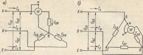
Fig. 1-1. Scheme of active power in the three-phase chain by one wattmeter when the star load is turned on (but)and triangle (b)
To the same conclusions, you can come when the load is turned on by a triangle. Turning from instant to medium values, we obtain expressions for active power:
Where  ,
, etc., as well as I. BUT ,
I. IN ,
I. FROM
- active values \u200b\u200bof linear stresses and currents;
etc., as well as I. BUT ,
I. IN ,
I. FROM
- active values \u200b\u200bof linear stresses and currents;  ,
, etc. D. - the angles of the phase shift between the corresponding currents and voltages.
From equations (1-1) - (1-3) it can be seen that for measuring the power, and therefore, the energies of the three-phase system can be applied by one device, two instruments or three instruments. The method of one device is based on the use of expressions (1-2) and is used in symmetric three-phase systems. In an asymmetric system, in which the values \u200b\u200bof currents, voltages and the angles of the phase shift of the non-modock are used, the method of two devices using expressions (1-3) is used.
Finally, in the most general case, including in a four-wire asymmetric system, on the basis of expressions (1-1), the method of three appliances is used.
Consider the methods of measuring the power, which also gives the presentation and on energy measurement methods.
^
Method of one device.
If the three-phase symmetric system is symmetrical, and the load phases are connected by a star with an affordable zero point, then a single-phase wattmeter is included according to the fig. 1-1, butand the power of one phase is measured. To obtain the capacity of the entire testing system, the wattmeter is lost. You can also measure the power when connecting the load phases with a triangle, but provided that the wattmeter serial winding can be included in one of the load phases (Fig. 1-1, b).
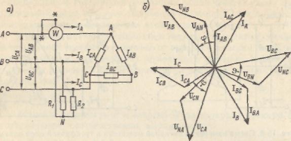
Fig. 1-2. Scheme of active power measurement in three-phase chain with artificial zero point (s) and vector diagram (b)
If the load is turned on with a triangle or a star with an inaccessible zero point, then the wattmeter is applied with an artificial zero point (Fig. 1-2, a), which is created using two additional resistors with active resistance  and
and  .
It is necessary to \u003d \u003d
.
It is necessary to \u003d \u003d  (- resistance of the parallel chain of the wattmeter). In fig. 1-2, b.the vector diagram corresponding to the diagram is shown. 1-2, but.Voltage
  ,
,  and
and  on a parallel winding and resistors, forming an artificial zero point, are equal to phase voltages. The angles between the phase voltages and phase loads of the load are indicated through
  . Because angles between vectors I. AU
andI. BUT ,
as well as between vectors and U. AU
equal to 30 °, the angle between the voltage vector applied to the parallel chain of the wattmeter, and the current vector I. BUT =
I. AU I. BUT fromin serial winding is also equal. Therefore, the testimony of the wattmeter
. Because angles between vectors I. AU
andI. BUT ,
as well as between vectors and U. AU
equal to 30 °, the angle between the voltage vector applied to the parallel chain of the wattmeter, and the current vector I. BUT =
I. AU I. BUT fromin serial winding is also equal. Therefore, the testimony of the wattmeter
Insofar as  and
and  ,
that
,
that  , i.e., the wattmeter shows the power of one phase. To obtain the capacity of the entire system, the testing of the wattmeter needs to triple. The same will be the same when connecting the load star.
To measure energy, this scheme is not applied due to the high inductance of the parallel chain of the meter.
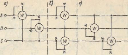
Fig. 1-3. Machining circuits of two wattmeters for measuring active power three-phase network
^
Method of two devices
.
This method is used in asymmetric three-wire chains of three-phase current. Based on expressions (1-3), we have three options for the inclusion circuit of two devices (Fig. 1-3, but- in).
An analysis of the work of wattmeters for these schemes shows that, depending on the nature of the phase load, the indication sign of each of the wattmeters may vary. The active power of the three-phase system in this case should be determined as an algebraic amount of the readings of both wattmeters.
^
Method of three devices.
In the case when the asymmetrical load is turned on with a zero-wire star, i.e. when there is an asymmetric three-phase four-wire system, three wattmeters are used, included according to the fig. 15-11. With such an inclusion, each of the wattmeters measures the power of one phase. The complete power of the system is defined as the arithmetic amount of the testimony of wattmeters.
Methods of one, two and three devices are mainly used in laboratory practice. In industrial environments, two- and three-phase wattmeters and counters are used, which are a combination in one device of two- (two-tempered) or three- (three-element) single-phase measuring mechanisms having
The overall rolling part to which the total torque is valid for all elements.
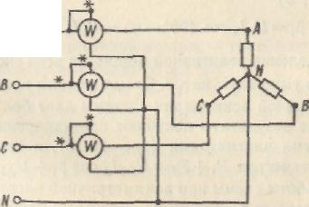
Fig. 1-4. Circuit measurement diagram three wattmeters
4. Measure the reactive power and energy in the three-phase chain.
The reactive power of the three-phase network can be represented as the sum of the reactive capacities of individual phases, i.e.
 Q \u003d.
With complete symmetry system reactive power
Measure reactive power (energy) three-phase network different ways: With the help of ordinary wattmeters (counters) included in special schemes, and with the help of jet wattmeters (counters).
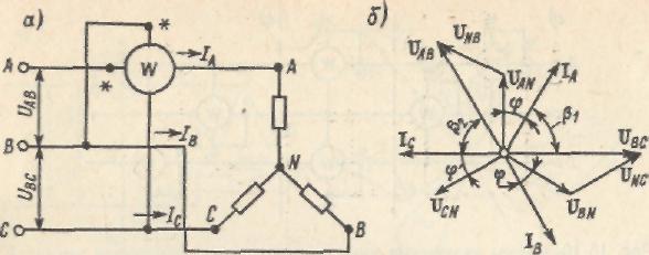
Fig.1-5. Including a wattmeter (a) to measure reactive power in a symmetric three-phase chain and a vector diagram (b)
With a complete symmetry of the three-phase network, the reactive power can be measured with one wattmeter included according to the figures. 1-5, but.Vattmeter readings (taking into account the vector diagram Fig. 1-5, b)
To determine the reactive power of the entire testing system, the wattmeter is multiplied by  . Scheme with one wattmeter Even with a slight asymmetry of the system gives great errors. The best results are obtained by measuring the reactive power by two wattmeters (Fig. 1-6), and at the same time the sum of the testimony of wattmeters
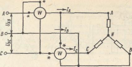
Fig. 1-6. The inclusion scheme of two wattmeters when measuring reactive power in an asymmetric three-phase chain
Analysis of the operation of the scheme with an asymmetric load is quite complicated, so we will limit ourselves to a private case when  And the system is symmetrical. In this case
  . To obtain the power of the three-phase system, the amount of testimony of wattmeters is multiplied by
  .
.
When the load is turned on according to the triangle diagram, the devices (wattmeters or counters) are included in the same way shown in Fig. 1-5, butand 1-6.
With an uneven load of the phases, but a symmetric voltage system (partial asymmetry), the reactive power of a three-phase network can be measured by two identical vattmeters of active power with an artificial zero point (Fig. 1-7, a). To create an artificial zero point n, a resistor R is used, the resistance of which is equal to the resistance of the parallel chain of the wattmeter. In a particular case of uniform loads of the phases, when F \u003d F 2 \u003d FZ \u003d F The sum of the testimony of wattmeters
= =
=
= .
.
To obtain the reactive power of the three-phase network, the amount of the testimony of wattmeters is multiplied by. 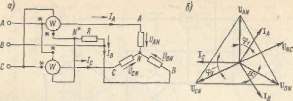
Fig. 1-7. The circuit for the inclusion of two wattmeters (a) to measure the reactive power in a three-phase network with partial asymmetry and a vector diagram.
Detailed analysis of the scheme of Fig. 1-7, and for uneven loads of the phases with a symmetric voltage system leads to the same result.
When measuring the reactive power and energy in three-wire and four-wire asymmetric networks, one three-element device or three instruments (wattmeter or counter) can be applied - Fig. 1-8, but.Proof of measurement features Consider for a particular case. The amount of instrument readings taking into account the phase alternation when the parallel windings are turned on as shown in Fig. 1-8, but .
![]()
Fig.1-8. The inclusion scheme of three wattmeters (a) for measuring reactive power in a three-phase (four-wire) network and a vector diagram (b)
From the vector diagram (Fig. 1-8,6) we find ![]() ,
, ,
,  . Since, then. To find the reactive power of the system, the amount of testimony of wattmeters must be divided into.
Based on this method, reactive meters are suitable for both three-wire and four-wire chains of three-phase current.
With indirect methods for measuring electrical energy, for example, when the electric power meters are calibrated, electrodynamic wattmeters and stopwalls are used.
5. Dimming power in alternating circuits at elevated and high frequencies.
In the alternating current circuits of increased and high frequencies, direct and indirect power measurements are carried out. In some cases, indirect measurements are preferable, as it is easier to measure the voltage, current and resistance than power. Direct measurements are mainly carried out using electronic wattmeters. In some electronic wattmeters, electrodynamic measuring mechanisms are used with a pre-amplification of current and voltage or with a preliminary straightening of these values. As a measuring mechanism, an electrostatic electromer with voltage and current amplifiers can be used, as well as magnetoelectric mechanisms with quadrators. Squares are performed on semiconductor diodes, transducers and other nonlinear elements, the operation of which is carried out on the quadratic area of \u200b\u200bthe Volt-ampere characteristic. Multiple operation uI
the quadrators are replaced by the operations of summing and construction in the square. In the frequency range to hundreds of megahertz, the wattmeters with the hall sensors are used. At ultra-high frequencies, power is measured by power transformation into heat (calorimetric methods), light (photometric methods), etc.
^
Power measurement by electronic rectifier wattmeter.
The schematic diagram of the electronic wattmeter with a square made on semiconductor diodes is shown in Fig. 2-1. Wattmeter has two resistors in the circuit of the current, the resistance of which  many less load resistance, and two resistor resistance
  ,
, in voltage circuit. Resistors and perform the role of the voltage divider, so the resistance is more load resistance
  .
.
The voltage drop on the resistors is proportional to the load current  ,
the voltage drop on the divisory resistor is proportional to the stress on the load, i.e. k. 2
and.As can be seen from the scheme, voltage and 1
and and 2
on diodes VD. 1
and
VD. 2
will be accordingly:
,
the voltage drop on the divisory resistor is proportional to the stress on the load, i.e. k. 2
and.As can be seen from the scheme, voltage and 1
and and 2
on diodes VD. 1
and
VD. 2
will be accordingly:
 ;
; 
When identical characteristics of the diode and work on the quadratic section of the Volt-ampere characteristics of currents  and i. 2
proportional to the squares of stresses.
and i. 2
proportional to the squares of stresses.
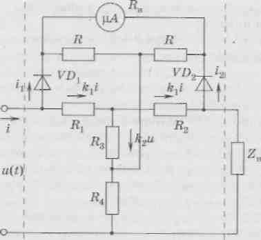
Fig. 2-1. Concept of electronic rectifier wattmeter.
Current in the device chain  .
Substituting in this expression value
and
.
Substituting in this expression value
and  ,
receive
,
receive
Where  .
.
The constant component of the current measured by the magnetoelectric device when
 and
and  proportional to active power:
Where R h. - Measured power.
Electronic wattmeters into the scheme of which diodes are included, have low accuracy (defining the non-identity characteristics of diodes), measurement error ± (1.5-6)%, low sensitivity, high power of consumption, limited frequency range (up to tens of kilohertz).
^
Measuring power thermoelectric wattmeter.
The frequency range can be extended to 1 MHz if the square is built on contactless thermal converters. The thermoelectric wattmeter differs from rectifying the fact that instead of diodes, the heaters of the contactless thermocouple turn on, and the thermo-emf difference at the cold ends, measured by a magnetoelectric malelololtmeter, is proportional to the average load capacity of the load.
Thermogottmeters are used when measuring the power in circuits with a non-sinusoidal form of current and voltage; When measuring power in chains with a large phase shift between voltage and current, when determining the frequency error of electrodynamic wattmeters.
^
Measuring the power of the wattmeter with the hall converter.
The Hall converter is a four-pole, made in the form of a thin semiconductor monocrystalline plate. Current conclusions T.-T.hall converter connects to an external direct or alternating current source, potential conclusions. X.-X.
(Hollovski), between which the EMF occurs at the moment when the magnetic field affects the plate - to the voltage meter. conclusions X.-X.
joined the side faces in the equipotential points in the absence of external magnetic field. Electromotive force Hall.  where to h.
- the coefficient whose value depends on the material, sizes and shape of the plates, as well as on the ambient temperature and the magnetic field values; IN- magnetic induction.
where to h.
- the coefficient whose value depends on the material, sizes and shape of the plates, as well as on the ambient temperature and the magnetic field values; IN- magnetic induction.
The electromotive power of the Hall will be proportional to the power, if one of the input values \u200b\u200b(for example, magnetic induction ^ C)make proportional tension and,and the other (for example, current i. H. ) - Current through the load.
Fig. 2-2. Wattmeter with a hall converter 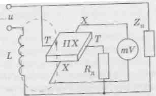 To implement the wattmeter, the Hall Converter ^ Pxplaced in the clearance of the electromagnet (Fig. 2-2), the magnetizing coil L.
which is powered by a current proportional to the load current, and through T.-T.passes current, proportional to the voltage attached to the load .
The current value is limited to an additional resistor.
To implement the wattmeter, the Hall Converter ^ Pxplaced in the clearance of the electromagnet (Fig. 2-2), the magnetizing coil L.
which is powered by a current proportional to the load current, and through T.-T.passes current, proportional to the voltage attached to the load .
The current value is limited to an additional resistor. ![]() .
Magnetic directions silest lines Induction vector INin the magnetic field of the core of the magnetic pipeline is shown in Fig. 2-2 dotted lines. Hall powerful power
.
Magnetic directions silest lines Induction vector INin the magnetic field of the core of the magnetic pipeline is shown in Fig. 2-2 dotted lines. Hall powerful power  registered by a magnetoelectric Millivololtmeter (to- proportionality coefficient).
Wattmeters with a hall converter allow measurement of power in the frequency range to hundreds of megahertz.
The advantages of these wattmeters are rapidness, simplicity of design, durability, reliability, and disadvantage - the dependence of the parameters on temperature.
^
Oscilloscope power measurement
.
The indirect methods for measuring the power include the oscillographic method, which is recommended to be used when the circuit is powered by a voltage of a non-substitutional shape, at high frequencies, low-power sources of voltage, the operation of electronic circuits in the key mode, the availability of nonlinear elements in the chain, etc. When operating electronic circuits in a pulse mode, instantaneous voltage values \u200b\u200bare measured by oscilloscope and(t.)
and current i.(t.)
on the studied section of the scheme during the time, equal to the period of the pulse (especially carefully, measurements during the rise and recession of the pulse) are especially carefully. According to the data obtained, stresses of voltage and current are built. Eppurane power value r(t.)
build on the work of the ordinate of voltage curves and(t.)
and current i.(t.)
for each moment of the time of the impulse.
According to the instantaneous power curve for the period, the maximum value of instantaneous power determines rand max , average value of power p and pulse power P and. To determine the average power value Rand pulsed power P and calculate the area, limited instantaneous power curve for the period, and then build a rectangle of equal area. If the base of the rectangle is equal to the duration of the pulse, then its height is the value of the pulse power P and, if the base of the rectangle is equal to the period of the pulses, the height of the rectangle is equal to the value of the average power R.
^
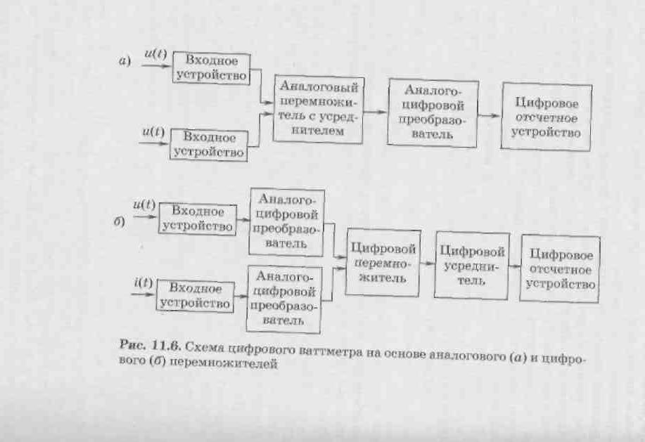
Measurement using digital wattmeters
Digital wattmeters are built on the basis of analog voltage multiple and(t.)
and current I. (t.)
(Fig. 2-3, but)or multiply discrete values and(t.)
and i.(t.)
(Fig. 2-3, b) followed by averaging work.
In digital wattmeters, made according to the conversion scheme and(t.) and i.(t.) in discrete values, which are represented by the corresponding digital codes, are multiplied and averaged with digital devices. These wattmeters have relatively high speed, determined by the characteristics of the ADC and the Motorizer. In digital wattmeters used the ADC of two-stroke integration, as well as built-in microprocessors.
6. Electric energy counters.
The device and the inclusion circuit of the induction meter are shown in Fig. 3-1, where 1 is a three-tricky magnetic core with voltage winding; 2
- counting mechanism; 3
- aluminum disc, fortified on the axis; 4
- a permanent magnet to create a braking torque; 5
- P-shaped magnetic circuit with a current winding. 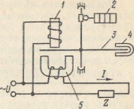
Fig. 3-1. Device and circuit on the induction meter
An analysis of the operation of the induction meter shows that the torque is proportional to the power of the alternating current, i.e.  ,
,
Where to- Permanent coefficient.
On the movable part of the counter (aluminum disk) there is a brake moment, proportional to the frequency of the disk. This moment is created as a result of the operation of the current in progress in rotating between the poles of the permanent magnet disk, and is determined by the expression
Where  - permanent coefficient;
  - rotation frequency
Disk.
Equating rotating and braking moments, we get 
Number of revolutions of the disk N during the time  Energy measurements are determined by the integral over time from the frequency of rotation of the disk
That is  ,
,
Where C \u003d.  -
constant counter; W-energy passed through the counter for the time interval .
-
constant counter; W-energy passed through the counter for the time interval .
Energy counting is performed according to the testimony of the counting mechanism - the counter of revolutions graded in units of energy. The unit of electrical energy (usually 1 kW * h), recorded by the counting mechanism, corresponds to a certain number of revolutions of the movable part of the counter. This is a ratio called a gear ratio BUT,specified on the counter.
The value, inverse gear ratio, i.e., the ratio of the registered energy to the number of revolutions is called the nominal constant with nom. Values BUTand with me, only depend on the design of the counting mechanism and for this meter remain unchanged.
Under the actual constant counter FROMunderstand the amount of energy that really passed through the counter in one turn of the movable part. The actual constant in contrast to the nominal depends on the current current, as well as on external conditions (temperature, frequency, etc.). Knowing FROMand sleep, you can determine the relative error of the counter
Where W. " - Energy measured by a meter, and a real value of the energy that has passed through the counter.
The active energy counters produce 0.5 accuracy classes; 1.0; 2; 2.5; reactive energy counters - 1.5; 2 and 3. The accuracy class of meters rations relative basic error and other metrological characteristics.
The state standard establishes the sensitivity threshold (as a percentage) of the meter determined by the expression  where 1
 - the minimum value of the current at which the counter disk begins to rotate non-stop; It is nominee for the counter value of the current in the current winding. At the same time, the voltage and frequency of the current in the circuit must be nominal, A \u003d 1. According to GOST 6570-75, the sensitivity threshold should not exceed 0.4% - for the counting class counters 0.5 and 0.5% for classes 1.0; 1.5 and 2. For the reactive energy meters of 2.5 and 3 value
  must be no more than 1 %.
The rotation of the disk in the absence of current in the load and in the presence of voltage in the parallel chain of the meter is called self-propeller. According to GOST 6570-75, the Samochode should not be at any voltage of 80 to 110% nominal.
The error of the counter depends on the mode of its operation, so the state standard is normalized by different relative errors at various loads.
Under the action of external factors, the meter appears additional errors, also normalized by the state standard. Additional errors occur due to distortion of the shape of the current and voltage curve, voltage and frequency oscillations, a sharp difference in power consumed by the load, and some other factors.
In addition to single-phase induction meters, industry also produces three-phase meters of active and reactive energy. Three-phase meters are like three (three-element) or two (two-element) counter, combined with one axis of rotation. Bay-element counters are used when measuring energy in three-wire three-phase circuits, and three-element counters - in four-wire chains.
7. Literature list:
1. Metrology I. electrical measurements: Tutorial for universities / B.I. Avdeev, E. M. Antonyuk, E. M. Dushin et al.; Ed. EAT. Soul. - 6th ed., Pererab. and add. - L.: Energoatomizdat. Leningr. 1987
2.Ribers and measurement methods electrical quantities: studies. Availability for athm following / E.G. Atamalyan. 3rd edition, recreation. and add. - M.: Drop, 2005
9. Measurement of electrical power
To measure the power in practical radio engineering, they are resorted throughout the frequency range - from DC to millimeter and shorter wavelengths from measuring power levels falls in very wide limits-from 10-18 to 108 W.
IN last years When measuring, along with absolute (watts, millivatt, etc.), relative (logarithmic) power units (decibels) are widely used. It is recommended that relative units of measurement have a number of significant advantages and are used to estimate the power of radiotechnical signals, the degrees of their amplification or Weakening, sensitivity of receiving devices, measurement errors, etc.
New opportunities in solving power measurement problems discovered achievements in the field of physics, microelectronics and especially digital techniques that allowed auto-matting the measuring procedure and conduct it in interactive mode
9.1. General
how physical quantity, electrical power is determined by the work of the co-retailed source electromagnetic field per unit time. The dimension of electrical power is written as follows: joule / sec \u003d watt.
Measurement of power in various frequency bands has certain features of electric power meters Industrial hour totes along with energy meters are the basis of the current accounting system for electricity consumption in the national economy. Power measurement on constant tok, and Also in the range of sound and high frequencies has a limited value, since at frequencies to several de shyatkov, megahertz is often more convenient to measure voltages, currents and phase shifts, and power to determine the calculated path. At frequencies of over 300 MHz, due to the wave nature of the processes, the voltage values \u200b\u200band currents are certainly the uniqueness and measurement results begin to depend on the place of connection of the device. At the same time, the stream of power through any transverse cross-section of the transmission line always remains unchanged. For this reason, the main parameter characterizing the operation mode of the microwave device becomes power.
Active (electrical circuit absorbed) single-phase alternating current power determines as
P \u003d uicosφ, (9.1)
Where u, i is the middle quadratic voltage and current values; φ - phase shift between instantaneous voltage and current values.
If the load is RN electrical chain purely active (φ \u003d 0), then the power of alternating current
P \u003d UI \u003d I2 RN \u003d U2 / RN, (9.2)
For an arbitrary form signal having a periodic structure, electrical power You can evaluate using a Fourier series:
P \u003d u0 i0 + u1 i1cosφ1 + u2 i2cosφ2 + ... + un incosφn, (9.3)
where U0, I0 are constant components; Un, in - average quadratic voltage and current harmonics; φn is a phase shift between the harmony-kami voltage un and current in.
The electrical power of the AC can be measured directly with the help of special devices - wattmeters, or indirectly by measuring the values \u200b\u200bincluded in the given ratios. The principle of operation of wattmeters is based on the implementation of multiplication operation. Apply direct and indirect multiplication devices. Examples of direct multiplication devices are the measuring mechanisms of the wattmeters of the electrodynamic system. Direct multiplication of voltage and current can be ensured using the hall converters, or special schemes on field transistors, etc.
In indirect multiplication devices, the product of quantities are as a result of using such mathematical operationsAs an addition (subtraction), the construction of the extent, logarithming, integration and pr. For these purposes, are analog integrated multiplers. Modern wattmeters at frequencies 1 ... 10 MHz are built on the basis of integrated multiplers using thermal converters.
Currently, it is necessary to measure the power and energy of the DC, the active power and energy of single-phase and three-phase AC, the reactive power and energy of three-phase AC, the instantaneous power value, and the amount of electricity
in very wide limits. Thus, the power of constant and single-phase alternating current is measured in the range from to the lower limit refers to the power of the alternating current of the high frequencies of radio engineering devices. The required accuracy of measuring the power of constant and alternating current is different for different frequency ranges. For constant and alternating single-phase and three-phase current industrial frequency, the error must be within the limits of ultra-high frequencies the error may be higher
Measuring reactive power is practical only in large consumers of electricity, which are always powered by a three-phase alternating current. The lower limit for measuring the reactive power of three-phase AC is at the level of several and the upper limit about the error of measuring reactive power should be within
The measurement range of electrical energy is determined by the ranges of changes in the nominal (maximum) currents and voltages. For energy consumed by various electrical devices, the lower limit of the current measurement range is approximately, and the voltages - however, measurement tools for direct measurement of such small energies do not exist, and small energy values \u200b\u200bare determined by indirect methods (for example, power and time is determined). The upper limit of the current measurement range reaches the voltage. The permissible error of energy measurement must be within
Measurement of reactive energy is only necessary for industrial three-phase chains. Therefore, the lower limit of the current measurement range in this case is at level 1 A, and the voltage is 100 V. The upper limit of the current measurement range with direct measurement of energy is 50 A and voltage - 380 V. The permissible measurement error of reactive energy should be at the level
In wide limits, it is also necessary to measure the amount of electricity: from measuring the amount of electricity in short-term current pulses (units of a milliculone) before measuring the amount of electricity flowing for a long time (up to CL). The permissible measurement error of the amount of electricity should be within
Power measurement ranges, energy, amount of electricity and the smallest error achieved by
Table 15-5 (see Scan)
modern means of measurements manufactured by the domestic industry are shown in Table. 15-5.
Measurement of power and energy of constant and alternating single-phase current.
To measure the power in the circuits of constant and alternating single-phase current, electrodynamic and ferrodynamic wattmeters are used, the principle of operation and the inclusion scheme is considered in § 5-3.
For accurate measurements of the power of constant and alternating current on an industrial and increased frequency (up to 5000 Hz), electrodynamic wattmeters are produced in the form of portable instruments of accuracy classes 0.1-0.5.
For power measurements in production conditions in the alternating current circuits of industrial or higher fixed frequencies (400, 500 Hz), shield ferrodynamic wattmeters of accuracy classes 1.5-2.5 are used.
For high frequency measurements, thermoelectric and electronic wattmeters are used.
When measuring low power at ultra-high frequencies, the use of electrometers is possible (see § 5-3).
For power measurements at high currents and voltages, wattmeters are usually included through measuring transformers of current and voltage.
Also indirect methods for measuring the power of constant and single-phase alternating current are also found. DC power can be determined using two devices: ammeter and voltmeter, and single-phase AC power - using three devices: ammeter, voltmeter and phazometer (or power coefficient meter). With different schemes for inclusion of instruments, the values \u200b\u200bof the methodological errors of power measurement are different, depending on the ratios of the resistance of the instruments and the load (similar to the errors of the wattmeter, § 5-3). With indirect measurement of power, it is necessary to make a simultaneous counting on two or three instruments. In addition, the measurement accuracy is reduced by summing up instrumental instrumental errors. For example, direct measurements of single-phase AC power can be carried out with the smallest error (see Table 15-5), while with indirect power measurements, the measurement of only power factor is possible with the smallest error and therefore, the overall error will exceed
To measure the power of the AC, the electronic oscilloscope is sometimes used, in particular to determine the power of losses on the hysteresis in ferromagnetic materials. In this case, the area of \u200b\u200bthe hysteresis loop turns out to be proportional to the loss power.
DC power measurement is carried out using DC meters.
The energy of single-phase alternating current is measured by induction meters of electrical energy (see § 5-3).
Electrical energy can also be measured using electronic electrical energy meters that do not have movable parts. Such meters have better metrological characteristics and greater reliability and are promising means of measuring electrical energy.
In chains of single-phase alternating current, the measurement of reactive power and energy is valid only with laboratory studies. In this case, under the reactive power, the reactive power of a single-phase chain can be measured as with the help of three devices (indirect method), so
and a special wattmeter having a complicated diagram of a parallel chain in order to obtain a phase shift between current vectors and voltage of this chain, equal to 90 °.
Measurement of active power and energy in three-phase circuits.
In the three-phase system, regardless of the load connection circuit (triangle or star), the instantaneous value of the system's power equates the sum of the instantaneous power values \u200b\u200bof individual phases:
The active power of P and energy over the time interval is determined, respectively, expressions:

where - phase voltages and currents; - cosine of the phase shift angle between the current and voltage in the load phases; T is a change period of alternating voltage.
For a symmetric three-phase system, in which all phase and linear voltages, currents and phase shift angles between the stresses and currents are equal to each other, these equations will take the form:

where - linear stresses and currents; - cosine the angle of the phase shift between the current and voltage in the load phase.
When the load is connected by the star (Fig. 15-8, a) instantaneous power where - instantaneous values \u200b\u200bof phase stresses; - Instant values \u200b\u200bof phase currents. Given that the equation for
Fig. 15-8. The diagram of measuring the active power in the three-phase chain is one wattmeter when the load is turned on by the star (A) and the triangle (b)
the instantaneous power value of the three-phase system can be represented in three forms:
To the same conclusions, you can come when the load is turned on by a triangle. Turning from instant to medium values, we obtain expressions for active power:

where as well as the active values \u200b\u200bof linear stresses and currents; - Phase shift angles between the corresponding currents and voltages.
From equations (15-1) - (15-3) it can be seen that for measuring the power, and therefore, the energies of the three-phase system can be applied by one device, two instruments or three instruments. The method of one device is based on the use of expressions (15-2) and is used in symmetric three-phase systems. In an asymmetric system, in which the values \u200b\u200bof currents, voltages and the angles of the phase shift of the unequal, use the method of two devices using expressions (15-3).
Finally, in the most general case, including the four-wire asymmetric system, the three-apparatus method is used on the basis of expressions (15-1).
Consider the methods of measuring the power, which also gives the presentation and on energy measurement methods.
Method of one device. If the three-phase system is symmetrical, and the load phases are connected by a star with the available zero
Fig. 15-9. Scheme of measuring active power in a three-phase chain with an artificial zero point (a) and a vector diagram (b)
point, the single-phase wattmeter is included according to the diagram. 15-8, and and measure the power of one phase. To obtain the capacity of the entire testing system, the wattmeter is lost. You can also measure the power when the load phases are connected by a triangle, but provided that the wattmeter serial winding can be included in one of the load phases (Fig. 15-8, b).
If the load is turned on with a triangle or a star with an inaccessible zero point, then the inclusion of a wattmeter with an artificial zero point is used (Fig. 15-9, a), which is created using two additional resistors with active resistance, while it is necessary to resist the parallel wattmeter circuit). In fig. 15-9, B shows a vector diagram corresponding to the diagram of Fig. 15-9, a. The voltage on the parallel winding and resistors forming an artificial zero point are equal to phase voltages. The angles between phase voltages and phase loads of the load are indicated by as the angles between vectors, as well as between vectors and are equal to 30 °, the angle between the voltage vector applied to the parallel chain of the wattmeter, and the current vector in the serial winding is also therefore, the wattmeter reading is also
Since avav, i.e. wattmeter shows the power of one phase. To obtain the capacity of the entire system, the testing of the wattmeter needs to triple. The same will be the same when connecting the load star.
To measure energy, this scheme is not applied due to the high inductance of the parallel chain of the meter.

Fig. 15-10. The inclusion circuits of two wattmeters for measuring the active power of the three-phase network
Method of two devices. This method is used in asymmetric three-wire chains of three-phase current. Based on expressions (15-3), we have three options for the inclusion scheme of two devices (Fig. 15-10, a - c). An analysis of the work of wattmeters for these schemes shows that, depending on the nature of the phase load, the indication sign of each of the wattmeters may vary. The active power of the three-phase system in this case should be determined as an algebraic amount of the readings of both wattmeters.
Method of three devices. In the case when the asymmetrical load is turned on with a zero-wire star, i.e. when there is an asymmetric three-phase four-wire system, three wattmeters are used, included according to the fig. 15-11. With such an inclusion, each of the wattmeters measures the power of one phase. The complete power of the system is defined as the arithmetic amount of the testimony of wattmeters.
Methods of one, two and three devices are mainly used in laboratory practice. In industrial environments, two- and three-phase wattmeters and meters, which are a combination of one instrument

Fig. 15-11. Circuit measurement diagram three wattmeters
Fig. 15-12. Wattmeter Inclusion Scheme (A) To measure the reactive power in a symmetric three-phase network and a vector diagram (b)
two- (two-element) or three- (three-element) single-phase measuring mechanisms having a common rolling part to which the total torque is valid for all elements.
Measurement of reactive power and energy in a three-phase chain.
The reactive power of the three-phase network can be represented as the sum of the reactive capacities of individual phases, i.e.
With complete symmetry system reactive power
You can measure the reactive power (energy) of the three-phase network in various ways: with the help of conventional wattmeters (counters) included in special schemes, and with the help of jet wattmeters (meters).
With a complete symmetry of the three-phase network, the reactive power can be measured with one wattmeter included according to the figures. 15-12, a. Vattmeter readings (taking into account the vector diagram Fig. 15-12, b)
To determine the reactive power of the entire testing system, the wattmeter is multiplied by a scheme with one wattmeter, even with a slight asymmetry of the system gives great errors. The best results are obtained when measuring the reactive power by two wattmeters (Fig. 15-13), and at the same time the sum of the testimony of wattmeters
Analysis of the operation of the scheme at an asymmetric load is quite complicated, so we will limit ourselves to a private case when the system is symmetrical. In this case, the amount of wattmeter readings

To obtain the reactive power of the three-phase network, the amount of testimony of wattmeters is multiplied by 3.
Detailed analysis of the scheme of Fig. 15-14, and for uneven loads of the phases with a symmetric voltage system leads to the same result.
When measuring the reactive power and energy in three-wire and four-wire asymmetric networks can be
Fig. 15-14. The inclusion circuit of two wattmeters (a) to measure the reactive power in a three-phase network with partial asymmetry and a vector diagram (b)
Fig. 15-15. (see Skan) The integration scheme of three wattmeters (a) for measuring the reactive power in a three-phase (four-wire) network and a vector diagram (b)
one three-element device or three instruments (wattmeter or counter) is applied - Fig. 15-15, a. Proof of measurement features Consider for a particular case. The amount of instrument readings taking into account the phase alternation when the parallel windings are turned on as shown in Fig.
From the vector diagram (Fig. 15-15, b) we find as it is to find the reactive power of the system, the amount of testimony of wattmeters must be divided into
Based on this method, reactive meters are suitable for both three-wire and four-wire chains of three-phase current.
With indirect methods for measuring electrical energy, for example, when the electric power meters are calibrated, electrodynamic wattmeters and stopwalls are used.
Measurement of the amount of electricity.
To measure the amount of electricity (see § 5-3) use ballistic galvanometers, couluters and ampere counters. All these devices are included in a circuit of the measured current or directly or with the help of shunt.
Ballistic galvanometers are used to measure small amounts of electricity flowing within short periods of time. The error in measuring the amount of electricity by a ballistic galvanometer largely depends on the ratio of the time of passage of the current pulse through the coil of the galvanometer and the period of free oscillations of its rolling part and can be
Coulithors are used to measure the amount of electricity in current pulses occurring from 0.05 to 2 seconds with a current amplitude from 20 to 200 mA. The reduced measurement error by the coulute meter does not exceed 5%. A feature of the work of the pendant meter is the need for consistency of the amplitude of the pulse of the measured current, i.e., the use of it is limited to measuring the amount of electricity of rectangular pulses.
Ampere counters are used to measure the amount of electricity flowing for a long time. For example, for example, for accounting for the number of electricity flowing in the battery load circuit, to account for the amount of electricity in electrolyactic workshops, etc. The reduced error of magnetoelectric ampere-hours meters does not exceed the reduced error of the amp-hours of the ampere no more than ± 1% . The above accuracy of the electrolytic meters of amps-hours is more and can reach