To categoriarity: Questions by electrics
How to measure the resistance to the earthing man spread?
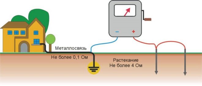
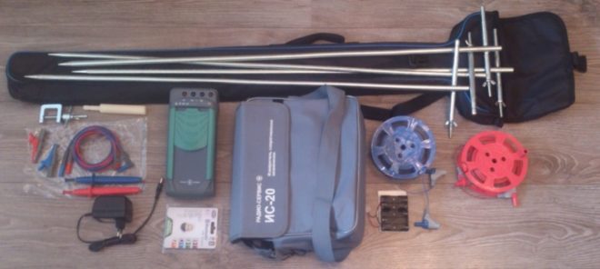
This resistance is usually measured according to the ammeter and voltmeter method using portable X-1, MS-08, M-416 devices, etc. If these devices are not, the earthing spreading resistance can be measured using a conventional ammeter and voltmeter according to the diagram shown in the figure. 1, a.
Current is the flow rate of electricity in the circuit. Using the same analogy with water, as before, a higher pressure and a large tube mean that the flow of water per second will be greater. This simple bond is represented by the equation known as the "Ohm Law".
Measurement of tension touch
Another important equation is power. Watts - this is a measure of work or conversion electrical Energy In some other form, such as warm, light or movement. As follows from the equation, it requires both voltage and current. On the other hand, if there is too much current, everything will be heated, and the components may be damaged. In extreme cases, there may be even smoke or flame.
As a source of measuring current, a welding or any other transformer can be used, in which the secondary winding has no electrical connection with the primary. The potential and current electrodes are placed in the way, as shown in Figure 116, b. In the reduced distance scheme, it is given to measure the resistance to spreading the center of the consumer substation, made in the form of a closed circuit. When measuring resistance to spreading single entrancersintended for repeated grounding of the zero wire of the power line, the specified distances can be reduced by 2 times.
What is grounding?
The reasons for measuring the current in the circuit include. Determination of the power requirements of the chain Checking the correct operation of the circuit. Checking the power supply. Make sure the batteries are charged or discharged with a reliable speed. Timing autonomous work or recharging time. . This counter has 4 ranges from 200 micro-mines up to 200 milliam. In addition, the setting of 20 milliamper can be used to measure up to 20 A when used with a special jack for an accurate probe.
This is a "auto band" and has only 3 very wide range of settings. It automatically adjusts the range to ensure the best measurement of accuracy in these settings. Micro amphibes Million amplifiers. . Measuring current with incorrect connection can damage your counter!
When measuring the impedance by spreading the earthing machine, the MS-08 device is placed in the immediate vicinity of the connection location to the tested earthing and collect one of the schemes shown in Figure 116, B or 116, g, which differ from one to another only by the fact that in the scheme. The instrument readings must be subtracted by the resistance value of the connecting conductor, which comes from the ground to the terminals 1 \\ and e \\. After assembling the scheme, the resistance of the potential chain is adjusted. For this purpose, the range switch is set to the "Adjustment" position and, rotating the generator handle with a frequency of about two revolutions per second, achieve the adjustment retirement of the appliance arrow to the red feature. If you cannot install the arrow on the red feature, it means that the sum of the resistance of the earthing and the potential electrode is greater than 1000 ohms and it is necessary to reduce the resistance of the potential electrode. For this, it is resorted to the local moistening of the earth with salted water, to the deeper embedding of a potential electrode or the use of several parallel connected rods scored to the ground at a distance of 3 ... 4 m one from the other.
This meter has a separate socket for measuring voltage and resistance. And two sockets for different current measurement ranges. One current measuring socket is safe for currents up to 200 mA. Another can be used to measure currents up to 20 amps.
These two meters use the same connector for all measurements other than high current measurements. This is the correct connector and range for use in measurements above 200 mA on this meter. On this meter right choice Nests and ranges for measuring with high current is clearly indicated by yellow.
Fig. 1. Schemes of measurements of the resistance to the earthing machine spreading: A - Schematic diagram; B - location of the electrodes; in - measurement of the earthing resistance; D - Measurement of total earthing resistance and connecting conductor
After adjusting the potential chain, proceed directly to the measurement. For this, the band switch is transferred to the "x 1" position. What corresponds to the measurement range of 10 ... 1000 Ohm, and rotating the generator handle, measure the resistance to the earthing machine. If at the same time the arrow falls on the non-working part of the scale (0 ... 10 Ohms), then switch to a smaller measurement range, the range switch to the "x0.1" or "x0.01" position is translated.
Also pay attention to the warning inscriptions indicating the maximum security levels for each nest. But with all meters, use caution when choosing a range and connections to avoid damage to the meter. Most counters have internal fuses to protect the circuit, but they are not always easily accessible for easy replacement.
Registration of measurement results
The correct installation of devices for connecting and grounding is important to protect personnel and equipment. During installation, test resistance is required to confirm electrical continuity to the ground. In addition, an effective program of inspection and maintenance is needed to ensure the continuity of the system. When evaluating maintenance requirements, the connection and grounding system can be divided into three categories.
The fact that the rules are required to periodically measure the ground resistance is not just someone's notion or fault, it is, first of all, the security issue of human life. There are certain standards and measurements must comply with them. In the article, we will look at how to measure the ground resistance by a multimeter and other measuring instruments.
Spot clamps are equipped with flexible conclusions, which are used to temporarily connect portable containers with a building grounding system. Fixed grounding cables and bus tires used to connect flexible wires and stationary equipment to the ground. Ground electrode itself. . Flexible wires are subject to mechanical damage and wear, as well as corrosion and overall wear. For this reason, they should be regularly verified. This inspection should evaluate the purity and sharpness of the clamping points, the rigidity of the clamp springs, the presence of broken threads in cables and the strength of cable fasteners.
Before checking grounding in a private house, it is very important that you understand the very essence of this procedure, for which it is being done, what is the main goal is, why is it necessary?
What is grounding?
Protective grounding is a deliberate connection from the land of those parts of electrical equipment, which, during normal operation of the power grid, are not under the action of voltage, but may affect its effect as a result of a breakdown of isolation. The main purpose of grounding is to protect people from action electric current.
A more thorough check should be carried out regularly using an intrinsically safe Ommeter to verify ohmic resistance and continuity. One Ommeter Output is connected to a clean stain on the container, the other wire is connected to the grounding tire, a metal pipeline or other stationary equipment. The measured resistance should be less than 25 ohms, and it usually is about one Ohm. Fixed conclusions and bus tires are usually not susceptible to injury or wear as temporary connectors.
They must be checked by an ommeter on an annual basis. One melting output must be connected to a fixed output or bus, the other wire must be connected to a grounding electrode of the plant or building structural steel. The measured resistance should be less than one Ohm. Conductive hoses must be regularly checked, and after repair or replacement - for electrical continuity and resistance. Conductive segments can be destroyed and cannot be repaired properly, which makes hoses with non-conductive or with abnormally high resistance.
The main component of the protective ground is the contour. It is a design of natural or artificial entrancers, that is, several grounding electrodes are connected to a single integer. As electrodes most often use rods from steel. Copper rods apply less often because it is expensive.

Non-conductive hoses with an inner spiral conductor must be installed so that the spiral conductor in contact with adjacent metal fittings. This can be a device installed solely for grounding purposes, such as a slave rod or hidden plate, or it may be an underground metal water supply. If the building has a steel frame, which is grounded to protect against illumination or otherwise, effectively grounded, this grounding is suitable for static grounding; A separate static grounding electrode is required.
But if there is financial opportunities, then keep in mind that copper is the perfect option and the best conductor.
By logic, it is clear that the earth contour should be located in the ground. Since we are interested in the protection of the house, then not far from the structure and the power shield is selected appropriate place with normal soil. Three pines are driven into the ground so that they are located triangle, and the distance between them was 1.5 m.
Preparation for work
Underground pipelines equipped with cathode protection are not suitable for use. Underground pipelines from cement-asbestos or plastic will not be satisfactory as soils. It is also possible that metal pipelines have sediments from plastic or cement-asbestos, which would make it unsatisfactory. Water counters must have jumpers constantly installed around them to ensure a continuous electrical path. When underground pipelines are used as soil, any shutdowns for changes or repair can make the grounding system inefficient.
These electrodes need to be driven as deeply as possible (their length should be at least 2 m).
Now you will need a welding machine and a metal tire, with which the electrodes need to be linked to an equilateral triangle. The contour is ready, now it is necessary to secure the copper conductor to it, which further goes into the shield and connects there to the grounding tire. And there are grounding conductors from all sockets on this tire.
Sprinkler pipelines and electrical wiring should be avoided due to the increased resistance to the ground caused by compounds and connectors. Continuity gap can also occur when removing pipelines and pipelines for repair or change.
Permissible values \u200b\u200bof the resistance of the Earth
It serves to dissipate the ground closure on Earth, as well as as a potential equalization system. The need to protect equipment grounding. Safety personnel safety equipment prevent or at least minimize equipment damage as a result of a heavy current stream.
What are the basics to achieve admissible resistance on earth
- Improving the reliability of the power system.
- Grounding system and earth.
- Equipment Equipment Earth connecting bodies.
Before use, you need to check the contour on the grounding resistance.
About what grounding is on the following video:
What is the essence of grounding work?
The principle of protective grounding is based on the main quality of the electric current - to flow through the conductors who have the least resistance. Many factors affect the resistance of the human body, but on average it is equal to 1000 ohms.
- Grounding resistance Reagent grounding grounds. Peterson coil.
- Ground.
Electric impedance, as a rule, is a measure of countering the circuit of the current when the voltage is applied to it. The input resistance is the impedance of the load network from the source network, including both static and dynamic opposition. Static opposition is better known as resistance, while the dynamic electrical opposition is known as reactivity. Load network is part electrical networkwhich consumes energy, while the source-network is a part that transmits power.

According to the rules of the electrical installation device (PUE), the ground contour must have resistance much less (no more than 4 ohms are allowed).
Now, see what is the principle of protecting grounding. If some electrical device is faulty, that is, the insulation test occurred and the potential appeared on its body, and someone touched it, the current from the surface of the device will go to the ground through a person, the path will look like " " This is a deadly danger, the current value of 100 mA causes irreversible processes.
Personnel qualifications requirements
The input impedance of the source network and the input impedance of the load network is determined how the current and voltage changes when the power is transmitted from the source to the load network. Impedance is often used to assess the electrical efficiency of the network, which is usually equal to the ratio of the useful output power to the total power consumption. This process usually includes splitting the network to the steps and receiving the input and output impedance between the steps. In the context of the impedance, the efficiency is the attitude of the input impedance to the complete impedance, which is the sum of the input impedance and the output impedance.
Protective grounding reduces this risk to a minimum. Modern electrical appliances have an inner connection of grounding contact of the plug with a housing. When the device is included in the socket through the plug and, as a result of damage, the potential appears on its body, it will go to the ground on a grounding conductor with low resistance. That is, the current will not go through a person with a resistance of 1000 ohms, but will run through the conductor who has much less this value.
These losses can lead to phase imbalance, which means that the current of the circuit does not correspond to the phase with its voltage. Thus, the power transmitted according to the chain is less than if the current and voltage were in the phase, since the power was the current and voltage product.
Measuring the resistivity of the soil
These systems usually consist of three components, including sensors, signal conditioning scheme and analog-to-digital converter. Sensors convert physical parameters into an analog signal. The signal generation circuit converts signals from sensors into a form that can be converted into digital values. Then an analog-to-digital converter converts conditional analog signals into digital values.
That is why an important stage in the arrangement of an electric farm in our residential buildings It is measuring ground resistance. We need 100% confidence that this value is below our human 1000 ohms.
And remember that this procedure is not a one-time character, the resistance should be measured periodically, and the contour itself must be constantly maintained in good condition.
Data recorders with low input impedance usually have the input resistance of about 22 com. The requirement for a data recorder with high input resistance means that it should have an input impedance of at least 100m, which significantly increases the cost of the device. Additional features for this type of data recorder include an analog-to-digital converter with a sequential approximation of 16 bits.
Electric shunt is a device that skips current around the point in the chain through the low-voltage path. It has many possible applications, such as an ammeter that allows an ammeter to indirectly measure the current, which is too large for measurement. This type of shunt is a resistor with a precisely known resistance, which is very little compared to the current in the load circuit. The shunt is consistently connected to the chain, allowing the tread to pass through it. The voltmeter can then be connected to each end of the shunt to measure the voltage drop on the shunt.
Checking grounding sockets
If you bought a house or apartment, and the entire electrical part in the room has already been mounted before you, how to check the ground in the outlet?
First, we suggest you to make a visual inspection. Disconnect the introductory machine to the apartment and disassemble one outlet. She should have the corresponding terminal to which the grounding conductor is connected, as a rule, it has a yellow-green color execution. If all this is present, it means that the socket is grounded. If you have discovered only two wires - brown and blue (phase and zero), then the socket does not have a protective ground.
At the same time, the presence of a yellow-green conductor does not yet indicate the health of grounding.
The efficiency of the contour can be defined by a special device, without which no electrical, multimeter costs. The algorithm for this check is as follows:
- In the camshaft, turn on the introductory machine, that is, voltage must be present in sockets.
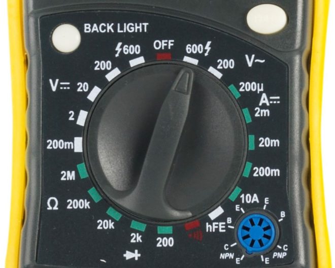
- On the device, set the voltage measurement mode.
- Now it is necessary to touch the appliance to the phase and zero contact and measure the voltage between them. The device should highlight the order of 220 V.
- Similar measurement, produce between phase and ground contacts. The measured voltage will be slightly different from the first magnitude, but the fact of the appearance of some numbers on the screen says that there is a grounding in the room. If there is no digits on the screen, it means that the ground loop is missing either in a faulty state.
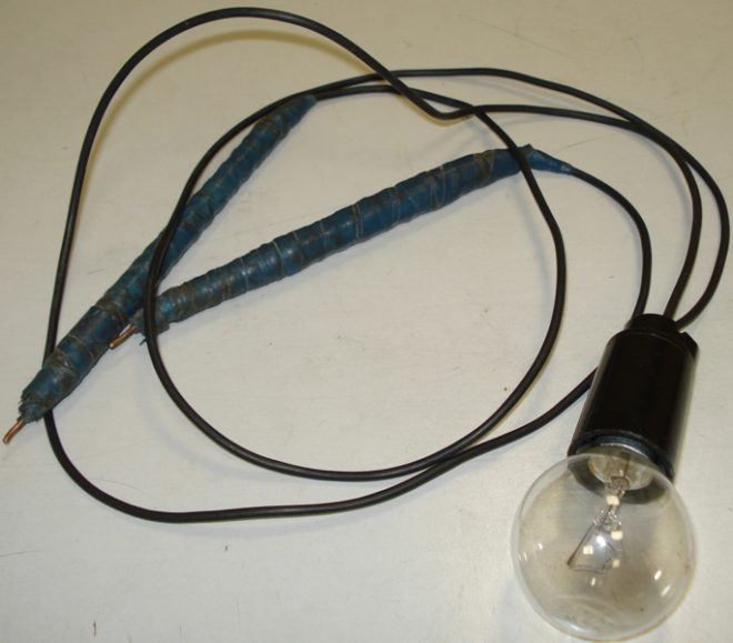
When there is no multimeter, check the operation of the circuit can be tester that is going to do it yourself. You will need:
- cartridge;
- light bulb;
- wires;
- crighters.
Electricians call a similar tester "control light" or abbreviated by the "control". Touch in one end probe to the phase contact, the second is touched to zero. The light bulb should light up. Now the confusion that you touched zero, move to the umbrelot of grounding contact. If the light lights up again, it means that the ground contour in working condition. The lamp will not burn if protective grounding Not working. A weak glow will be evidenced by the poor state of the contour.
If the RCD is connected to the circuit, then during verification actions it can work, this means that the grounding contour is operational.
Note! There may be such a situation that during the touch of terminating to phase and grounding contacts, the lamp did not catch fire. Try then from the phase contact to move the dipstick to zero, it is possible during the connection of the rosette zero with a phase was pop by.
Ideally, it is necessary to start checking actions from the fact that with the help of an indicator dumping to determine the phase contact in the switch apparatus.
Vitely this method is shown in the video:
There may also also testify such indirect situations on a faulty either nonconnected grounding circuit:
- cleaning the washing machine or a water heating boiler;
- noise is heard in the speakers when the music center works.
Conducting measurements
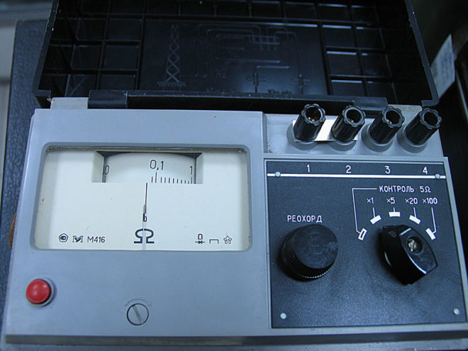
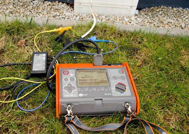
And yet in the question, how to measure grounding resistance, it is better not to use a multimeter, but a megoometer. Na the best option It is considered an electro-measuring portable device M-416. Its work is based on the compensation method of measurement, for this use the potential electrode and auxiliary earthing. Its measuring limits from 0.1 to 1000 ohms, it is possible to operate the device at temperature modes from -25 to +60 degrees, the power is carried out due to three batteries with a voltage of 1.5 V.
And now step-by-step instruction In total process, how to measure the resistance of the ground loop:
- The device is placed on a horizontal level surface.
- Now make it calibration. Select CONTROL MODE, press the red button and holding it down, set the arrow to the "zero" position.
- There are some resistance to connecting wires between conclusions to minimize this effect. Place the device closer to the measured earthinger.
- Select the desired connection scheme. You can check the resistance roughly, for this conclusions, connect with jumpers and plug the device along the three-step circuit. For measurement accuracy, an error that the connecting wires will be given, that is, the jumper is removed between the outputs and the four-way connection diagram is applied (by the way, it is drawn on the device lid).
- Earn the auxiliary electrode and the probe rod to the depth of at least 0.5 m, keep in mind that the soil must be dense and not bulk. For clogging, use a sledgehammer, blows should be straight, without swinging.
- The location where you will connect the conductors to the ground, clean the paint file. As conductor, use copper veins with a cross section of 1.5 mm 2. If you use a three-step scheme, the file will perform the role of connecting probe between the earthing and the output, since the copper wire of 2.5 mm 2 is connected on the other side.
- And now we go directly to how to measure the ground resistance. Select the range "x1" (that is, multiplication to "1"). Press the red button and rotate the handle arrow to "zero". For large resistances, it will be necessary to choose a larger range ("x5" or "x20"). Since we chose the range "x1", then the digit on the scale will correspond to the measured resistance.
Visually, how to measure grounding in the following video:
Some basic parameters and rules
No matter what time of year you will produce measurements, readings should always comply with the following standards:
Ideal time is the middle of summer (when the soil is dry) and the middle of the winter period (when the earth is stigled).
Wet soil will strongly affect the spreadability of the current, so measurements carried out in crude and wet weather in the spring or autumn period will be distorted.
There is still a way to produce measurements with current ticks, but the best option will be the appeal to the specialized service. The electrical laboratory will produce all the necessary measurements and will issue the appropriate protocol in which the place of tests will be indicated, character and resistivity Soil, measurements of measurements with a seasonal correction factor.