(Simplified calculation)
1. Magnetic materials and their properties
From the whole variety of magnetic materials, we will stop on magneto-soft ferrites, because They are able to operate in a wide range of both frequencies (from hundreds of Hz to hundreds of kHz) and temperatures (from -60 ° C to + 155 ° C no more).
It should be noted that at frequencies - below 10 kHz, the dimensions of the electromagnetic elements are overpriced, which determines the limitation of the application.
Ferrites have a large, resistivity, therefore, and neglect small losses for vortex currents. However, the losses on the magnetization associated with the "viscosity" of the material are significant and reach 3 ... 5%. Therefore, the efficiency of transformers usually lies within 0.95. ..0.97. 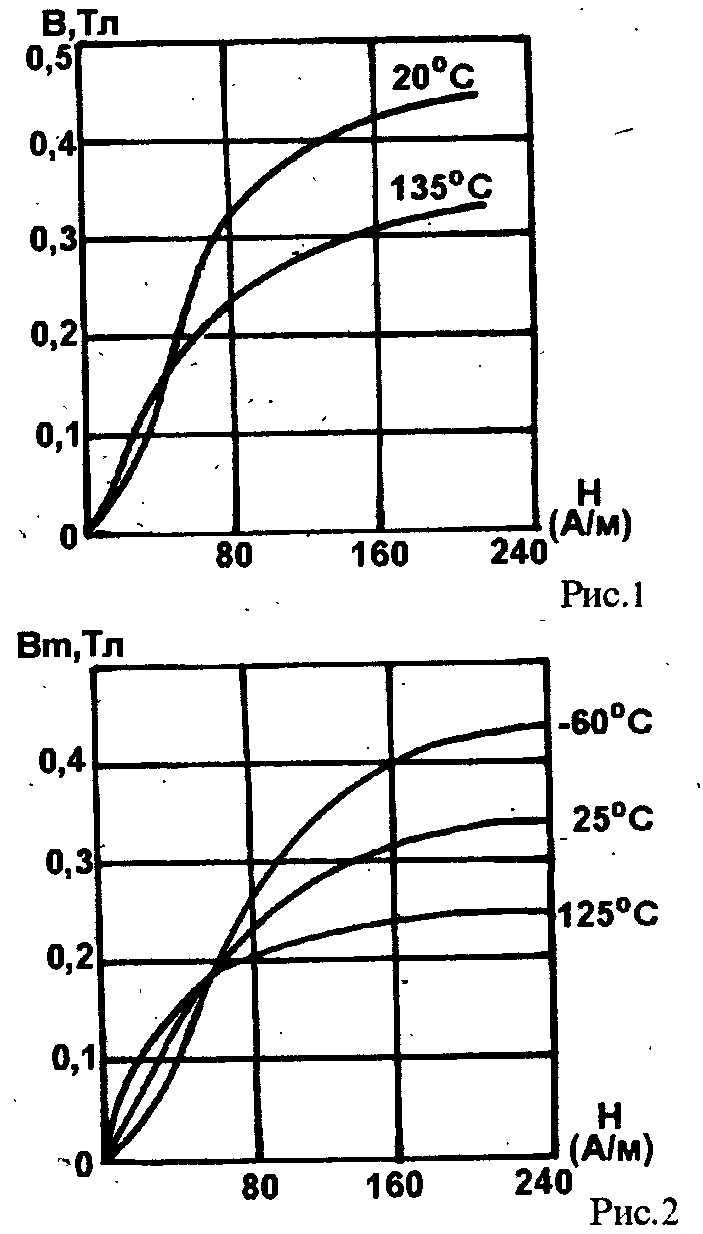 From the latest developments, the most promising are Ferrites of brands 2500NMS1 and 2500NMS2 as having, unlike other brands, a negative temperature dependence of losses. The use of ferrite M2500NMS2 brand allows you to reduce weight by 8% and dimensions by 15%, and while maintaining the former sizes - increase the power by 20%.
Ferrites 2500HMS1 and 3000 NMS have small losses in strong magnetic fields In the range of frequencies adopted in television technique, increased magnetic nonduction at high temperatures ambient And when applied. Ferrite cores are used, as a rule, in relatively weak magnetic fields with tension of no more than 10 a / cm. In the field of middle fields (to NT inclusive), the permeability increases with increasing induction, which causes a slow growth of losses. When moving to the region of strong fields, permeability begins to decrease and no longer compensates for the increase in induction, as a result of which the loss increases sharply. It follows from this that the value of W and there is the maximum allowable induction for any ferrite.
The residual induction of VG in strong fields (over W) can be 0.3 ... 0.6 induction of BS saturation.
Saturation induction, operating frequency range and ambient temperature for some ferrite brands are shown in Table. one.
The Curie point of the selected ferrite should exceed the maximum operating temperature at least 30 ... 40 0 \u200b\u200bC. Induction W is the maximum permissible, because The transition to the stronger fields area leads to a sharp increase in losses. In fig. Figure 1 shows the dependence of magnetic induction for the material of 2500 NMS from tension and temperature. A similar dependence for material 1500 nm is shown in Fig.2
The dependence of the magnetic permeability on the tension of the magnetic field caused by the applied dCfor different materials Shown in Fig.3.
The effect of air gap on magnetic permeability is shown in Fig.4.
The tension of the magnetic field of the transformer with the direct current of the DC is determined:
H \u003d IO * N / L M, a / cm (1)
where I is the power of DC, and;
n is the number of turns;
L M - effective value of the length of the average force line, cm. 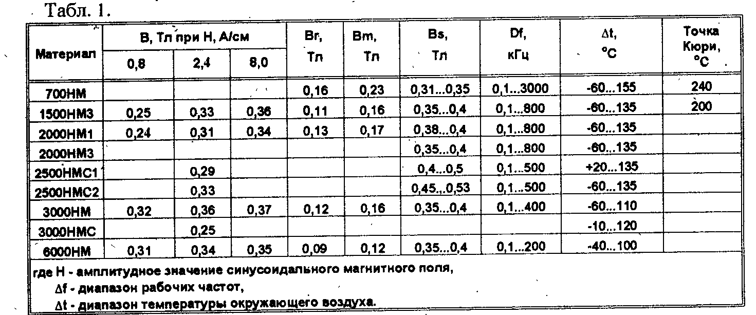
2. Core sizes and their characteristics
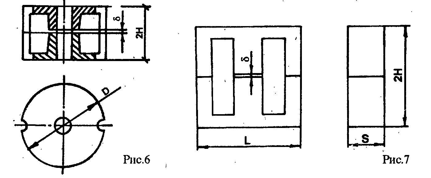
From all the varieties, we will focus on the three main types: ring, armored glass and W-shaped, which are shown in Fig.5 ... 7.
The implementation of miniaturization of secondary power sources (IVEP) is through the path of increasing the frequency of the conversion. This makes it possible to significantly reduce the dimensions of the motor products -transformers and chokes. For this purpose, ring and armor cores are best suited. Ring cores have some advantage, because Have a larger winding space. For transformers with energy accumulation (for example, ONPS, see Junction) and for chokes with a recharge (PHI ... PHIII), an armor core is preferable for the possibility of creating a non-magnetic clearance.
The armor core is a good magnetic screen for the winding, located inside it, since the maximum value of the WT induction is achieved only in the central section, and in the rest of the core it is small. At the same time, the magnetic properties of ferrite (primarily magnetic permeability) are sufficiently high, since the core has a large margin in terms of magnetic material. Due to this, the core has a softer transition from the linear area to the saturation area. Sometimes the gap is performed not throughout the core section, which makes it possible to improve the properties of ferrite in a wider range of loads. In addition, the cores of this type are conveniently fixed on the radiator.
The ring core can create a smaller level of electromagnetic radiation compared to armored vehicles, but due to the asymmetric winding it may be necessary to shield it. ".
When performing transformers and chokes on ring magnetic pipelines, the highest magnetic permeability is ensured, interference decreases and electromagnetic properties are improved, since The magnetic field is concluded in space, limited by windings. With increasing frequency of the transformation, the advantage of toroidal cores is growing. With the same amperm, induction in ring magnetic power plants is greater than in armor, which reduces the mass and size of the transformer.
W-shaped cores are also inferior to the ring, since the latter have the best heat sink properties due to the larger cooling surface of the windings.
Armor magnetopers are applied in cases when required:
- High Quality in a given strip;
- the ability to regulate inductance;
- ensuring a small coefficient of nonlinear distortions made;
- high resistance to mechanical and climatic influences;
- No scattering fields.
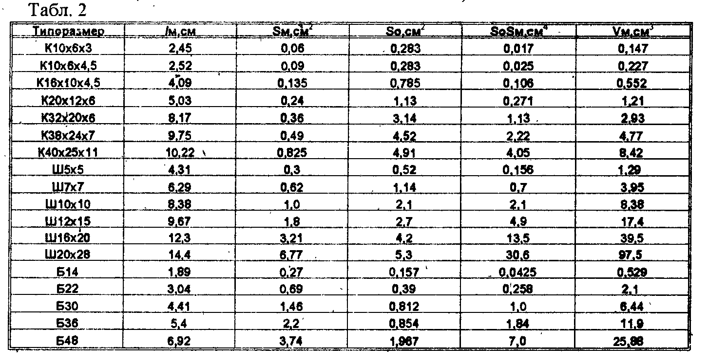
The main geometric parameters of some magnetic core cores are shown in Table. 2, where:
SM is the effective importance of the magnetic crossing section;
SO - the area of \u200b\u200bthe magnet windows window;
VM \u003d LM * SM is an effective amount of the magnet pipeline.
3. Inductivity
The initial inductance values \u200b\u200bfor some sizes of magnetic pipelines are given in Table. 3.
The values \u200b\u200bof the initial inductance of Al and effective magnetic permeability, depending on the size of the gap for the W-shaped cores, are shown in Table. four. 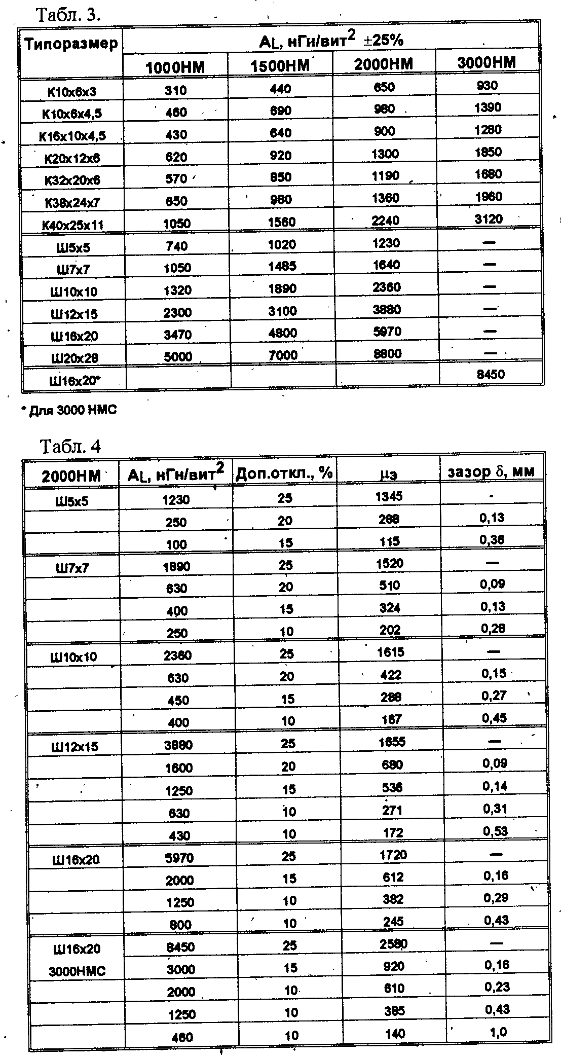
Hudctivity of the coil is equal to L \u003d A L * N 2 (2),
Where n \u003d (L / A L) -2 (3).
Example of calculation 1:
ML 500NM Core K10x6x3
N \u003d 300.
L \u003d?
Coil inductance according to formula (2)
L \u003d A L * N 2 \u003d 440 * zoo 2 \u003d 40 10 6 NGN \u003d 40 mG
Example of calculation 2:
Core M2000nm sh7x7
N \u003d 10.
L \u003d?
L \u003d 1840 * 10 2 \u003d 184 * 10 3 NGN \u003d 184MKHN.
For any other magnetic pipeline ^ not specified in the table, the inductance of the coil with a ferromagnetic core, which almost the entire flow closes through the core, can be calculated by the formula:
(4),
Where n \u003d 8920 * 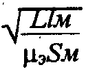 where \u003d 4 * 3.14 * 10 -9 Gn / cm - the magnetic permeability of the vacuum; - effective value of the initial magnetic permeability.
Note with weak variables magnetic fields (in M< 0,05 Тл) и отсутствии подмагничивания постоянным током эффективная магнитная проницаемость равна начальной, которая приводится справочниках для каждого типоразмера сердечника (для кольцевых магнитопроводов входит в марку феррита) и измеряется на частоте не более 10 кГц при напряженности поля Н не более 0,4 А/см.
From the expression it follows that the inductance of the coil with the same number of turns depends on the ratio of SM / L M, and since with an increase in the core, both SM and L M are about the same degree, their ratio remains approximately constant. Therefore, with the same number of turns of the inductance of coils wound on small and large rings with the same magnetic permeability, roughly coincide. A large ring has an advantage in the case when the coil is needed.
The boundary frequency of the magnetic pipeline material, starting with which it is necessary to partitioning the windings: 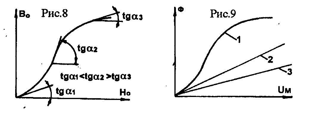
FRP \u003d 1000 /, MHz.
Example of calculation 3:
ML 500NM Core K10x6x3
N \u003d 300. 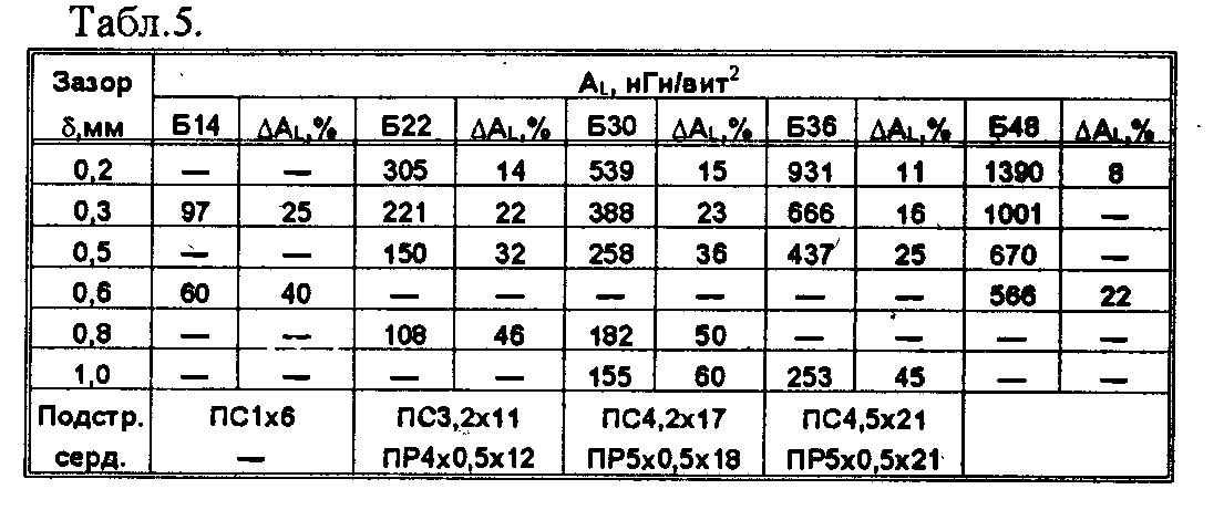
L \u003d? "
Crop inductance according to formula (4)
L \u003d 1.26 * 10 -8 * 1500 * 300 2 * 0.06 / 2.45 \u003d 0.04 GG \u003d 40 mG.
Example of calculation 4:
Core M2000nm sh7x7
N \u003d 10.
L \u003d?
L \u003d 1.26 10 -8 * 1490 * 10 2 0.62 / 6.29 \u003d 184 10-6GH \u003d 184 μH.
As can be seen from examples 1.3 and 2.4, the results coincide.
With an increase in amplitude alternating current Effective magnetic permeability, and therefore, the inductance of the coil is increasingly increasing in 1.5 ... 2 transmission (depending on the brand of ferrite and current value). With the increasing constant component of the current, and therefore the inductance of the coil, fall. The dependence of the dynamic magnetic permeability from the submagnetic is shown in Fig.8
The introduction of the air gap is equivalent to parallel inclusion of the inductance due to the magnetic flux in the magician (with a nonlinear Weber-ampere characteristic - Fig.9, curve 1), and a stream in the gap (with a linear characteristic - Fig. 9, curve 2). As shown in Fig. 9, curve 3 is the most effective approximation of the dependence of L (I) to the linear when working with the changing current of the submagnetic.
Where the magnitude of the gap, see in amateur conditions it is achieved by the flushing of the ring into two parts followed by their gluing.
Most often inductance must be adjustable. For this purpose, armored-type cores are most suitable. The initial inductance, depending on the size of the gap, the types of trimmed cores and the overlap coefficient (inductance range) for cores from the material of 1500 nm are shown in Table5.
To obtain stable parameters of the parameters of the inductance, the cores are subjected to aging (the effects of a temperature of 10 ... 15 ° C above the upper working for 48 hours), after which the coils assemble are subjected to cyclic effects of elevated (+ 85 ° C) and reduced (-60 ° C) temperatures - at least five cycles.
4. Transformers. Overall power of magnetic pipeline
The core of the transformer magnetic pipeline is chosen based on the necessary overall power: 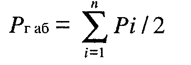 where Pi \u003d UI * II is the power of the i-th winding. As you can see, the overall power of the transformer is equal to half the power of all windings (both primary and secondary). It usually takes it equal to the amount of capacity of all loads. Since the throttle has only one winding, the overall thickness of the throttle is twice as high as the transformer power, i.e. The weight of the throttle is twice as smaller than the mass of the transformer at the same electromagnetic power. Suppose we have the simplest transformer with one primary and one secondary windings. We use the famous formula for EMF induction: U \u003d 4.44 * F b M * SM * N * 10 -4, in (8) and expression for winding current:
I \u003d js m km10 2 / 2n, a (9),
where km \u003d Sn n / SO \u003d (0.1 ... 0.35) is the coefficient of filling the window with copper; \u003d (0.5 ... 0.75) W - for magnetic pipelines of single-stroke voltage converters (OPON) and throtters with a gap; Bm-br \u003d 0,25bm - for LC-filter chokes without a gap and without a diode turned on; Km \u003d 0.15 for ring magnetic engineering; Km \u003d 0.25 ... 0.35 for the other magnetic lines (km for chokes above, because all the window takes one winding); 0,095 ... 0,97-efficiency of the transformer. Disposable transducers with the "direct" inclusion of the diode can operate with approaching to 2B m, if we introduce forced magnetic tube recharge. From formulas (11) and (12) it follows that from the same core in the two-stroke converter can be removed the power of 3 ... 4 times more than in one-way, because, first, more than twice the value And secondly, the introduction of the gap due to a decrease in magnetic permeability requires a larger number of turns of the windings in the same winding space. Therefore, one-stroke transducers with the "reverse" inclusion of the diode are used in relatively simple and low-power stabilized IVEPs (up to 100 W), when a good filtering of the voltage pulsations of the primary source is required, and the load is a variable character. Did you know,
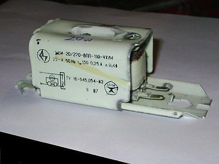
What is a mental experiment, Gedanken Experiment? Relativists and positivists argue that the "mental experiment" is a very useful intrusion for checking theories (also arising in our mind) for consistency. In this they are deceiving people, as any check can only be carried out independent of the inspection object. The applicant's hypothesis itself cannot be checking its own statement, since the cause of this statement itself is the absence of contradictions visible to the applicant. This we see on the example of a hundred and from that turned into a kind of religion, managing science and public opinion. No amount of facts that contradict them cannot overcome the Einstein formula: "If the fact does not correspond to the theory - change the fact" (in another version "- the fact does not correspond to the theory? - The worse for the fact"). Maximum, what a "mental experiment" can claim is only on the internal consistency of the hypothesis within its own, often not the true logic of the applicant. According to practice, this does not check. This check can only take place in a valid physical experiment. An experiment on the experiment that he is not a cure of thought, but testing of thought. Consistently in itself thought cannot check itself. This is proved Kurt Gödel. Cylindrical inductor, the length of which is much higher than the diameter, called solenoid, Magnetic field inside a long solenoid uniformly. In addition, often solenoid call a device that performs mechanical work due to the magnetic field when the ferromagnetic core is retracting, or electromagnet. In electromagnetic relays call winding relay, less likely - electromagnet. When used to accumulate energy called induction storage. To increase inductors, there is often a closed or open ferromagnetic core, interference chokes of high-frequency interference have ferrodyelectric cores: ferritic, flux, from carbonyl iron. Throsts designed to smooth ripples of industrial and sound frequencies have cores from electrical steel or magnetic alloys (Permalloev). Also, cores are used to change the inductance of coils in small limits by changing the position of the core relative to the winding, as a rule, a ferromagnetic core. On the microwave, when ferrodyeelectrics lose high magnetic permeability and dramatically increase the losses, metallic (brass) cores are used for this purpose. Properties of inductance coil: The inductance of the coil is proportional to the linear sizes of the coil, the magnetic permeability of the core and the square of the number of turns of the winding. The inductance of the coil wound on the toroidal core: With a consecutive connection of coils, the total inductance is equal to the sum of the inductors of all connected coils: With parallel combination of coils, total inductance is: Wire losses are caused by three reasons: Dielectric losses (wire insulation and coil frame insulation) can be attributed to two categories: In general, it can be noted that for modern coils of the overall use of loss in dielectric is most often negligible. The losses in the core are folded out of losses for vortex currents, losses for the magnetization of the ferromagnet hysteresis. The alternating magnetic field induces the vortex EDC in the surrounding conductors, for example, in the core, screen and in the wires of adjacent turns. Arriving with vortex currents (Foucault currents) become a source of losses due to ohmic resistance of conductors. With the resistance of losses, the other characteristic is tightly connected - Quality. The quality of the inductance coil determines the relationship between the active and reactive resistances of the coil. Quality is equal Sometimes the losses in the coil are characterized by a tangent of the loss angle (the value, inverse voluntaryness) - shift of the current phases and the coil voltage in the sinusoidal signal circuit relative to π / 2 - for an ideal coil. At frequencies below its own resonance, this effect is manifested in a voltage drop with increasing frequency. To increase the frequency of its own resonance, complex coil winding circuits are used, partitioning one winding into separation sections. TKI is a parameter characterizing the dependence of the inductance of the coil from temperature. Ballast choke. Previously used as reactive resistance for luminescent lamps inductor inductor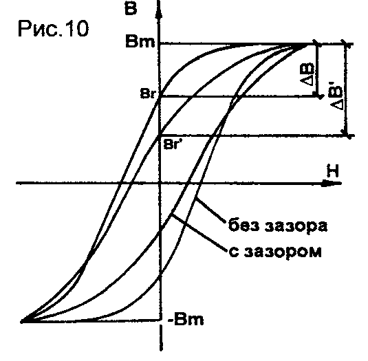 Sn is the cross-sectional area of \u200b\u200bthe wire, mm2; N is the number of turns. Alternating U to i, we obtain an expression for dimensional power: RGAB \u003d UI \u003d 4,44F B M S M SO NJK M 10 -2 / 2N \u003d 2.2S M SOFB M JK M 10 -2, BT (10) Since the range of change Induction with symmetric magnetization is 2W, the expression (10) can be rewritten in the following form: RGAB \u003d SMSO F JKM10 -2, W (11) from the formula, it follows that, with other things being equal in the case of the higher Km, the higher the use of this magnetic power plant . For this purpose, a rectangular wire is sometimes used, and the coils are performed by frameless, which makes it possible to bring km to 0.7 against the usual 0.5. In addition, flat wires have a smaller surface effect (the effect of current displacement). To select a magnetic pipeline, it is convenient to use the work of SOSM, characterizing electromagnetic power: (12), where - the range of changes in magnetic induction in the core during the action of the TN pulse. TL (Fig. 10); \u003d 2bm.
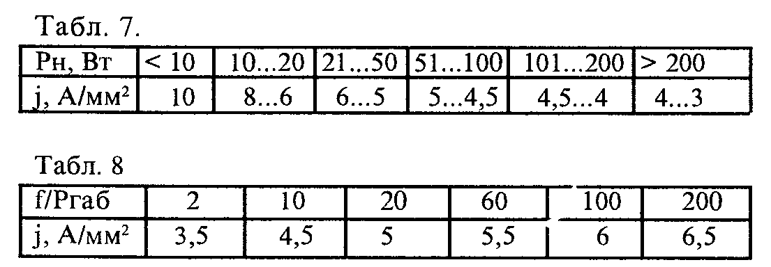
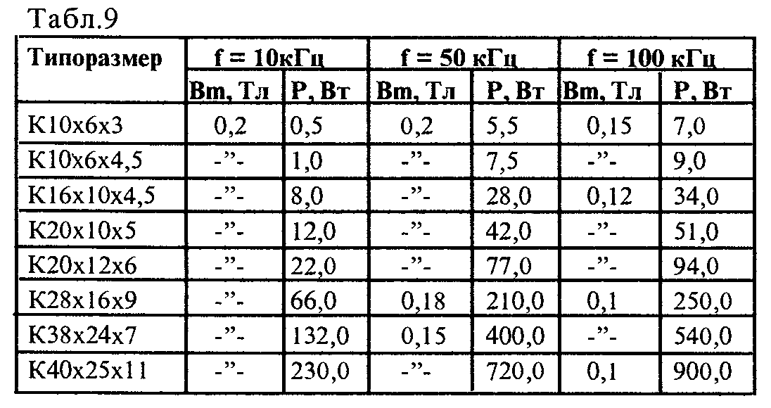 Disposable converters with a "direct" inclusion of the diode Although allowing work with large, applied with load power as a rule, no more than 350 W.Whukhatta converter with the output of the middle point of the primary winding of the transformer (the Roure scheme and the like) are used to 300 watts. The two-stroke semicircle is usually applied to 700 W, over 700 W - two-stroke pavement. The recommended value, taking into account the change in the lubricating loop in one-way mode, is given in Table. 6. The cross-sectional area of \u200b\u200bthe wire Sn \u003d IE / JN mm 2 (13) along with this Sn \u003d 3.14d 2/4 (14) solving equations 13 and 14 relative to D we obtain d \u003d 1.13 * (IE / JN) - 2 (15) where IE is the effective value of the current, and; j - current density, a / mm2; N - the number of parallel connected wires; d - wire diameter, mm. The density of the current J in the windings of the transformer is chosen according to the table. 7 or 8. To simplify the selection of ring magnetic and yes, from the M2000NM material, it is convenient to use the estimated data given in Table. 9. One of the basic requirements for electrical parameters of transformers is to reduce to some level of LS scattering inductance, on which the magnetic coefficient has depends between the windings and, accordingly, the transformer transformer coefficient. Kmc \u003d (L 1 * L S) / L 1. The cost of a good magnetic connection between the primary and secondary windings of transformers at low levels of output voltages is difficult due to a significant difference in the number of turns of the windings. The inductance of scattering can be reduced by the breakdown of the primary winding into two parts, one of which dangles in the lower layer, and the second is in the upper, after the secondary one. More Best Ruzultates can be obtained if you have a primary and secondary winding together, for which the primary winding is broken into several windings with a number of turns equal to the number of turns of the secondary winding, which are then connected sequentially. In the winding of transformers on ring magnetopers in order to avoid barcase Cocking the windings on the core sharp edges of the magnetic pipeline should be bought. To increase the streaming of the coil, the windings should be placed close to each other. Winding, between which it is necessary to obtain a good streaming, must be separated from each other with minimally necessary insulation and the turns of one should be located above the turns of the other on the same type of winding. If the windings differ significantly to the number of turns, it is advisable to wind up with two or several parallel wires. The primary winding is broken into three sections woundlessly with a frameless method and an isolated fluoroplastic ribbon. The secondary winding is four volumetric two-dimensional sections, stamped from sheet copper with a thickness of 0.5 mm in the form of rings, cut and diards and also insulated with fluoroplastic ribbon. The primary winding sections are located between the secondary sections, and the annular electrostatic screens made of fine copper foil are embedded between them. Salted transformer core is clamped between two radiators. The use of such a method of performing the windings made it possible to obtain the inductance of scattering, which constitutes only 5% of the inductance of the primary winding.
This is a non-existent practice, otherworldly, the imagination of what is really not. Mind experiments are similar to sleeping. They give birth to monsters. Unlike a physical experiment, which is an excellent test hypotheses, a "mental experiment" focusfully replaces the experimental verification desired, not tested in practice with conclusions, manipulating logic-shaped constructions that really violate the logic itself by using unproved parcels as proven, that is, by substitution. Thus, the main task of the applicants of "mental experiments" is the deception of a listener or reader by replacing the present physical experiment by its "doll" - fictitious reasoning under honestly without the very physical inspection.
Filling the physics imaginary, "mental experiments" led to the emergence of an absurd surrealistic, confused-tangled picture of the world. This researcher should distinguish such "candy" from these values.Design
Properties of inductance coil
Resistance loss
Losses in wires
Dielectric losses
Losses in the core
Vortex current losses
Quality
Temperature Inductance Coefficient (TKI)
see also
Notes
Links
Passive solid states
Resistor · Variable Resistor · Strip Resistor · Varistor · Condenser · Variable Condenser · Strip Condenser · Inductor ·
Quartz resonator · Fuse · Self-planting fuse · Transformer
Active solid states
Diode · LED · Photodiode · Semiconductor laser ·
Diode Schottki · Stabilitron · Stabystor · Varicap · Varopond · Diode bridge ·
Avalanche ·
Tunnel diode ·
Diode Ganna
Transistor ·
Bipolar transistor ·
Field-effect transistor ·
CMOS transistor ·
Single-pass transistor · Phototransistor · Compound transistor · Ballistic transistor
Integrated circuit ·
Digital integrated circuit ·
Analog integrated circuit
Thyristor · Symistor · Distoror · MemristorPassive vacuum
Bartter
Active vacuum and gas-discharge
Electric lamp ·
Electrovacual diode · Triode · Tetrod · penter · Hhexode · Hepod · Pentagride ·


