The article we will talk about the methods of connecting one, two and more light bulbs in one and two-vector switches, the schemes that will simplify the course of work are considered.
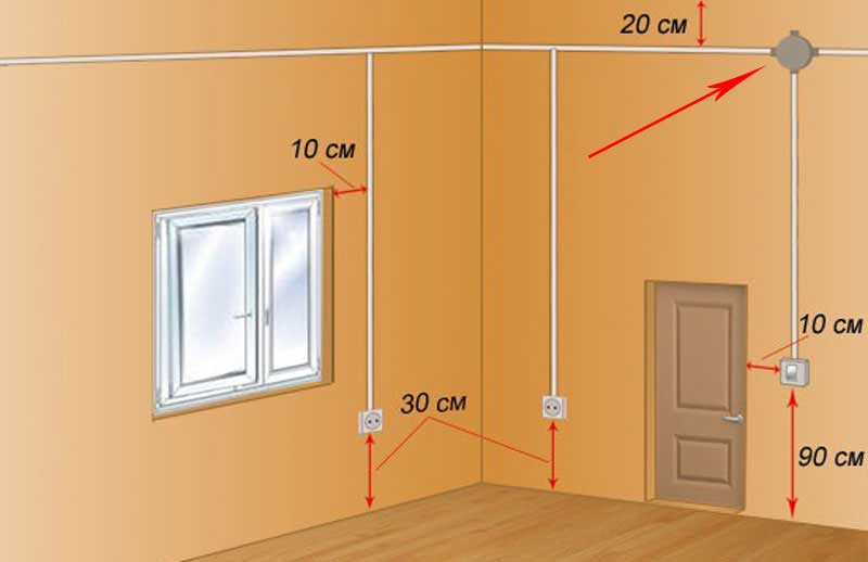
General Indoor Electrification Scheme
The general scheme of electrification of the room can be divided into two parts - nourishing consumers and provides lighting.
In the first case, everything is simple - wiring is thrown from the switchboard, (it is separated from the need), thanks to which the branches are created, and is summarized to the outlets by which consumers are connected to the power grid.
The sockets themselves are constantly under voltage after the connection.
In the case of the organization of lighting the room, then not everything is so simple, since it is necessary to create a branch that provides for the possibility of de-energization of lighting elements - light bulbs.
To do this, the circuit provides switches (switches), whose task is to interrupt and restore the voltage supply circuit to the consumer.
For the normal functioning of the lighting in the room and ensure security, there are certain schemes for connecting the lighting devices through the circuit breakers to the power grid.
Moreover, there are several varieties, which allows you to organize the connection of the bulbs according to the planning provided.
For example, with just one chipboard, you can control the lighting of several rooms, and independently of each other.
Previously used switches that crawled into wiring. That is, it was thrown away from the switchboard directly wiring to the bulb cartridge, and then in the right place the phase live wire was cut, and the interrupter was installed in this gap.

This method of settling the lighting elements is now practically not used and the types of power supply lamps are somewhat different, but the principle is used the same.

General provisions
The features of the creation of such branches are largely dependent on the number of lamps connected to them, as well as their controls using the chopper.
But in any case, the created branch includes:
- Switch (single, two-, three-block);
- Lamps with cartridges;
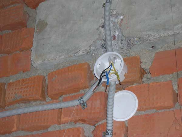
- Junction box;
- Wires (two- and threefold).
A little about the features of the operation of the interrupter.
Any switch has two outputs - input and output (the latter can be several).
At the same time, both of them relate to the same line, that is, if the phase is connected to the input output, it will also be at the output.
By moving the key to a certain position, the connection or disconnection of the contacts of these conclusions is performed, thereby closing the circuit-opening of the chain.

Safety.
Before describing how to connect methods, we immediately recall the safety technique during work.
To avoid defeat electric shock, It is necessary to deraid the power grid, and take measures to prevent accidental resumption of electricity to the end of work.
It should be restored only after full gasket and connect all the components of the branch, as well as ensuring reliable insulation of the connecting places of the wires.
One lamp - one switch
The simplest scheme consists of one lighting element and a single-wave chopper.
Theoretically, the connection does not differ from the above-described - zero living goes directly from the switchboard to the consumer, but the interrupter is performed into the phase. But almost everything looks somewhat more complicated.
To connect this type, first of all, you should decide on the installation site of the junction box.
It should be set, as close as possible to the location of the switch, the ease of access to it should be excluded.
From this directly depends the number of wires required to create a branch. Its optimal location - under the ceiling above the chopper.
- We determine the location of the lighting element - the lamp (for example - in the center of the ceiling);
- Select the installation site of the interrupter (conditionally below the junction box);
- In the junction box we bring the wiring coming from the distribution shield;
- On the ceiling, we lay the wiring (for the possible shortest path) from the lamp cartridge and also we will bring it to the box;
- It remains to lay the wires from the switch to the distribution box.
For simplicity, the wire coming from the shield to the box is denoted as "input", and from the box to the consumer - "output".
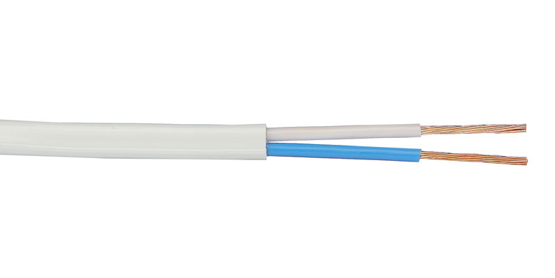
For a single-color switch and one lamp, two-tier wires are used.
After laying all the wiring (open or closed method), it remains only to connect everything correctly and it is important to determine which vein - phase, and what is zero.
You can learn using an indicator screwdriver by making an appropriate check on the outputs from the switchboard before turning off the power supply.
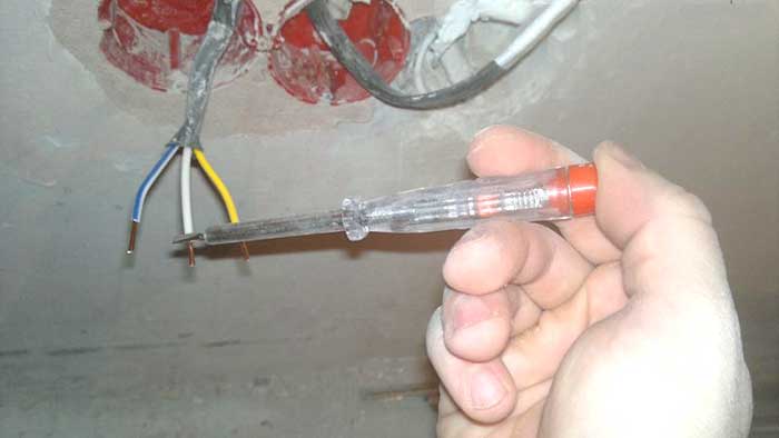
To make it clearer, consider how to connect everything correctly, using a different collapse of the braid wiring.
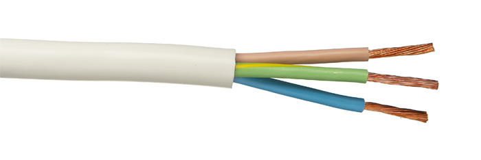
For example, to create a branch of the lighting element, a wire with veins painted in brown and blue colors was used.
When the introductory wire is connected to the distribution shield, the brown core joined the phase output, and blue with zero.
Knowing it, it remains only to combine everything in the junction box.
Since "zero" goes directly to the consumer, then the blue (zero) input duty connects with the corresponding living output.
It remains to include a switch in the circuit. From it to the distribution box, the two-tier wire will also be thrown, but in this case it is two parts of one line (phase).
We take a brown (phase) input core and connect it with any of the lived, for example, also with a brown leading on the switch.
It remains only the blue core, which runs from the switch, to connect with brown residential output.
![]()
This we looked at a detailed way to connect one lamp to a single block interrupter.
All subsequent schemes are built according to the described principle, so we indicate only their key points.
Connecting a two-layer switch
The next will be the scheme in which a two-block switch is involved.
A feature of its design is the presence of two output conclusions, each of which can be connected to the input (phase) output independently of each other.
This allows you to create two separate branches from one input wire, to control the powered power of the switch key.
Usually a two-block switch is used to power two lamps, but there are situations where only one lighting element is needed, that is, create one branch.
In this case, the connection does not differ from the above described above. The only one should decide which key will be the working and to its output conclusion to connect the phase core.
With this connection, the second key will be disabled.

Now consider the features of connecting two light bulbs to such a breaker. That is, in fact, we create two branches from one phase vein.
The difference from the scheme described above is reduced to the fact that we will have two outputs from the box (each on your lamp).
That is, the distribution box should include 4 wires - introductory, two output and switches.
Yet important moment - From the interrupter to the distribution box, you will have to lay a three-cable wire.
One of the lives will be connected to the input output of the switch, and the other two to the output.
For example, the third color in the trigger cable will be green.
The connection is done like this:
- Zero wire (blue) from entering with two output colors with two output (there should be a twist consisting of three veins);
- Introductory phase wire (brown) connect with the same color leading to the switch;
- Two other cable veins leading to the switch must be combined with phase conductors of the conclusions. That is, blue needs to be connected with a brown one branch, and green - with a brown other branch.
A color switch is the simplest product designed to control the lighting of the house.
From time to time, such products have to be repaired or replaced, so it is desirable to submit the scheme for their inclusion and principle of operation.
In our article you will find answers to your questions, scheme and video recommendations for connecting a single-wave switch.
The switch is part of the scheme, which includes the source and consumer of electricity. In this embodiment it network at 220 V and Lamp. To enable and turn off such a lamp between it and the network there must be a disconnecting device.
The switch having one key is turned on sequentially in the network phase line. In principle, it can be included in the zero line, but this, firstly, will contradict rules of Pue., and, secondly, it will be unsafe when servicing electrical apparatuses.
The danger is that when installing the device in the zero line, the energy consumer nodes will be under voltage even when it is in the off state. And when touched to the electric device, a person may be affected tok.
To connect the lighting lamp to the network using usually used in which switching is performed. At the same time to her suitable 6. electric lines - By two, voltage is served, two go to the lamp and two go to the switch.
How to choose correctly
Depending on the type of electrical wiring (or), switches of one or other species can be applied in the house. They differ in their design in terms of installing them on the wall. In the first case, the device is installed on a wooden plate placed on the wall surface, in the second - a metal or plastic peavern in the wall in the wall.
In any case, when choosing a switch, you should pay attention to its limit characteristics. Typically, the magnitude of the working voltage of the standard apparatus is 220 V, and the working current -10 A.
The passport also indicates the maximum switched power (standard -2.2 kW).
At the same time, the power of the consumer, for example, the lighting facilities of the house, should not exceed this maximum power.
Installing and Video Instructions
When installing the light control system the most attention should be paid to:
- The correct connection of the elements in the distribution box (block).
- Proper connection of the switch itself.
Connection diagram of a single block switch to a light bulb:

To fulfill the first rule, the following operations must be done:
- DetermineSuitable from the network side. To do this, you can use a probe with an neon light bulb. If you bring the probe to the phase, the neon light bulb will start glowing. If the probe will bring to zero, then the glow will not be.
- Disable meals on the apartment.
- Connect the phase with one of the switches to the switch.
- Connect the second cable running from the switch, C, which is suitable for the central contact of the base of the lighting lamp.
- Connect with a network zero wire that comes from the external contact of the base.
The compound of stripped ends can be carried out in various ways:
- twist and subsequent soldering with further isolating this place with ribbon or special caps;
- screw or bolted clamps;
- with the help of terminal shoes;
- spring clamps, for example, WAGO type.
The most reliable contact in this case provides the first option. Screw and bolted connections are reliable, but if they are performed, damage to the connected elements is possible. Spring clamps can be performed very quickly, but over time the springs weaken, which leads to sincerity and burning.
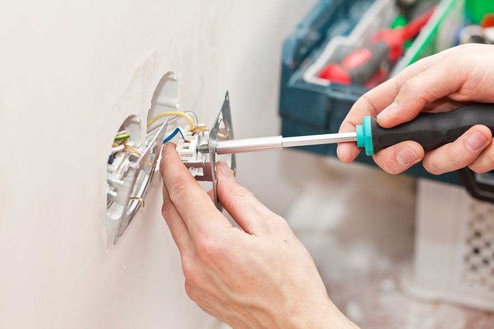
To fulfill the second rule, you need to perform such operations:
- Remove the device key With a screwdriver with a thin stale. It should be borne in mind that modern plastic instrument buildings have a very fragile structure, so it is necessary to act carefully.
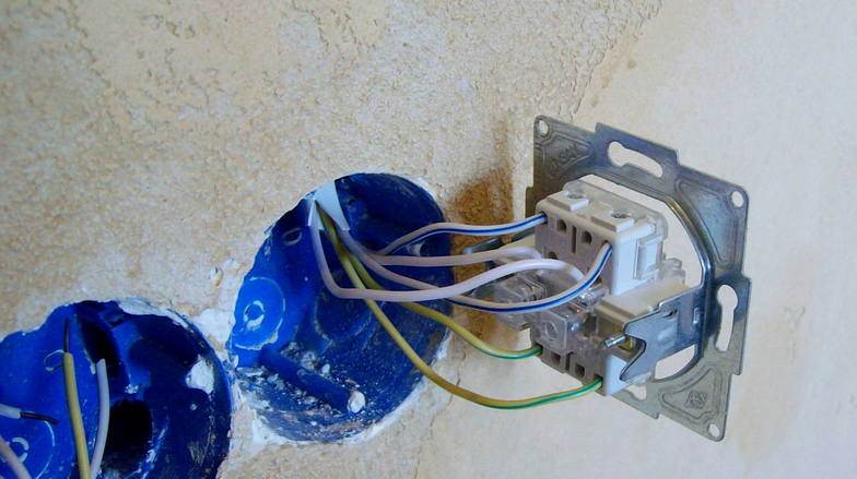
- Strengthen the invoice of the device with screws On wooden conversion. Connect the conductors from the distribution block to the contacts.
- With hidden wiring first conduct wires. Then the housing is installed in the wall niche and secure it with special legs by tightening the mounting screws.
- Set the key to the place.
Learn from this video, how to connect a single-block light switch:
In the next video, we will tell you how to install a single block switch correctly:
In conclusion, it is necessary to include on the panel and check the performance of the system and its adjustment.
Let's summarize. To control the disconnection of electricity consumes, such as lighting are used colorless switches. Such devices are included in the phase wire sequentially with the lighting means.
Installation of a system for disconnecting devices using electricity is made using a special junction box.
Instrument must be chosen so that it limit electrical characteristics were equal or more such characteristics of current consumers.
Before you implement a circuit of connecting a switch to a light bulb, you need to think in advance how electrical equipment will be placed. The markup is better to put on the wall so as not to miss some trifles. Now you have to make switching of wires and installation of equipment, and you need to do it so that everything works fine. In this article, we will help to figure out how to connect and implement the safe further operation of the instruments.
Important! The main rule of the instruction is to disable electricity from the network to avoid the electrician.
Typically, the switch is installed on one phase core, when it is turned off, the network is opened, as a result, the voltage to the light is not supplied. It is worth noting that the connection of the circuit to another can be unsafe.
To place the wiring in the distribution box, it is necessary to stretch the cable that feeds the entire room, then the wires coming from the switch and light bulb. Thus, one wire from the bulb connect with a zero residential, connected to a common network, the remaining - with the conductor of the switch. The second veins of the switch connects with the phase conductor of the total power system. As a result, we get the connection of the workers lived a lamp and a common wiring through the switch. Using a similar method, when switching the lamp switch, this part will be disconnected. electrical chain From meals.
What do you need to implement the scheme?
Be sure to be directly installation, select the switching method, preferably the connection with terminal blocks or spring clips. After that, refer to our list and specify which means will be needed for wiring:
Errors and malfunctions in the question how to connect the switch to the light bulb
Often expected from the installation work is not carried out. All because in the process of connecting the electrical wiring there were disorders or you missed some details. So, if the light does not light up when the switch is turned on, you need to make a call of all the current parts.
Be sure to check the indicator whether the voltage from the network is fed to the switch. In the case of its absence, it can be safely argued that errors were made when connecting conductors with a common power plant.
You can conduct electrical work on connecting such switches yourself yourself, for which you should consider all the features of the device, connection schemes and other nuances.
The design of modern switches is simple, but quite fragile.
Often it is represented by the following elements:
- Key - The element on which is based on when using a switch. It is worth noting that it is quite simple to remove it, as it is attached to the plugs. A small effect will make it possible to remove the key itself from the landing site.
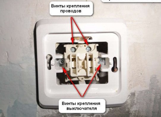
- After the key was removed, You can see the screws of the switch to. They hold the housing at the landing place.
- Also, in the case there are screwswhich are designed to fasten the electrical cable. They also conduct electricity and when unscrewed or twisting when a de-energized chain.
When considering the design, it is worth disconnecting the supply of electricity and check the availability of a voltage using the indicator. Plastic parts of the design do not conduct electricity, but inside there are elements that are under voltage.

Connection scheme
In order to spend proper connection Switch, you should pay attention to the connection scheme.
Often it consists of the following elements:
- Machinewhich can be located in an apartment or on the paint platform. It works as short closure Or a strong voltage jump, allows you to de-energize one or several rooms immediately depending on the type of power scheme that was used.
- where the electrical cable is often connected or its branching.
- Switch.
- Consumer of electricity.
A detailed connection scheme is as follows:
- With a flat shield or machine 2 cables are served: one phase and "zero".
- Zero Immediately goes to the consumer of electricity.
- Phase It goes to a classroom switch.
- In the closed state The chain is open, the phase is broken on the switch.
- The second part of The circuit breaker through the box goes to the consumer of energy.
- When turned on There is a connection of the chain.
Similarly, the conventional energy consumer is connected. The scheme is simple, and to create it does not need to have special skills or knowledge.
A feature of the connection of the switch with 1 key can be called the supply of only 1 wires with a phase on the switch and its output, for example, on the lamp. In order to carry out the work of the protective automaton, it is also necessary to bring the "Zero" electricity consumer.
Required tools and materials
voltage indicator
In order to work independently need to have the following tools:
- Indicator - Special device that allows you to determine the availability of current in the conductor. Without this tool, no work is carried out with electricity. The cost of the indicator is small.
- Screwdriver Need to take place the switch and the cable clamp in the landing jacks. When choosing, it is worth considering that manufacturers often use curly bolts. The screwdriver must have a handle from the insulating material. The longer the rod, the greater the screwdriver protection.
- Pliers We will be needed to clean the cable and its fit under the landing sockets. Use pliers are also needed with handles that are made of insulating material.
Also, do not forget that the hull socket must be exactly adjusted under certain sizes. Depending on which the material is made of the base, you can use a perforator or other tools for the formation of excavation.
During the work, the following materials may be needed:
- Cablewhich is selected taking into account the arising load.
- Insulating materialwhich is represented by the tape.
- Junction box.
- Switch itself.
Having in stock The above materials and tools can be processed.
Step-by-step installation instructions
The installation of the connection scheme under consideration is performed in several steps.
At the same time, it is worth considering the location of all elements first, take into account their features:
- The first step can be called the placement of the junction box. When choosing its location, you need to consider the following:
- It should be located away from water or the source of moisture.
- If possible, the junction box is taken to the wall. For her, create a niche.
- When choosing a location, you need to consider the location of all the elements of the chain and choose the shortest path of their connections. After the location was chosen, we carry out the installation of the junction box.
- Next step You can call the creation of a shock for a cable or a protective box if its recess will be held. The cable is laid and carried out through the junction box. When trimming the cable at the power source, consumer and switch, the reserve should be left. Connection to the power source is carried out last.
- Third stage You can call the creation of a landing niche for a switch box. Selects the most appropriate place And a hole is formed, which is accurately adjusted for the sizes of the case. If it is completed from above, we simply plan the location. After that, we carry out the following works:
- We insert the box in a niche and carry it out with the help of screws that need to be tied up.
- The ends of the cable that previously cleaned, should be shortened to the desired length, insert into the seats and clamp the screws. You do not need to leave long ends, as they may come in touch, and the KZ will arise. However, very short ends are also a problem: If the cable burned out over time it must be cleaned and its length may not be enough. These nuances should be taken into account when conducting work.
- Cable cable inside the case cannot be left. We carry out their insulation and wept in different directions.
- Connect the cable to the consumer.
- We connect the cable to the energy source that must be de-energized.
- We carry out isolation of all connections that are.
- Install the key to the place.
- Turn on the power supply. If there is an automatic, it will select it when the mistake is made. When you first turn on, you should be near the machine for some time to be ready to quickly de-energize the chain. Similarly, a simple chain is carried out with a mechanical interrupter.
Safety technique
Special attention when working with electricity is worth paying safety techniques.
With its consideration, the following nuances can be noted:
- All works Performed only with de-energization of the chain. Do not hope for your accuracy and attentiveness.
- After de-energizing the chain You need to make sure that no one will turn it on by chance. To do this, you can close the key to the key, put a person who will stand near him.
- Despitethat the machine was turned off, it is worth checking the lack of current in the chain. It may be due to the fact that the machine is faulty, or that when creating the chain there were branches that were not through the automatic. This is often found in old houses.
- Despite dealershipsYou can contact a power circuit with a connected conductor to a screwdriver.
- Work It can only be performed under the condition of normal humidity in the room.
- Cable Cannot be laid in raw walls.
You can perform the above work independently for one or more hours. When performing work, you should not hurry, as you can allow errors. Special attention should be paid to cable connections and strive to make them as little as possible. This is due to the fact that it is the compounds that consider the main vulnerability of the chain.
Hello dear site readers. The idea of \u200b\u200bthis article suggested Denis F, for which he thank you very much.
People who are not strong in electricity are faced with the problem of self-connecting conventional incandescent bulbs by the number of three or more pieces, and there are situations when you need to add your own.
For example, you bought a kitchen set or a wardrobe, and naturally all this with backlight. Repair in the apartment is made, and the wires for connecting the bulbs are not provided, the question arises, how nevertheless make backlighting without violating the integrity of the walls and wallpaper. The output can always be found.
And so, let's go.
Suppose you have a socket from you in the kitchen or in the hallway, from which you can take the supply voltage of 220V. This can be done in two ways.
The first is the easiest, this is when the entire scheme is connected to the outlet through the usual plug. Here everything is simple, the plug inserted and they forgot about it, and turn on and turn off the light with a typical switch.
The second method is distinguished by only the fact that you need to open the outlet, and the wires can be placed directly onto her terminals.
All work performed only when the voltage is turned off 220V.
The figure below shows the mounting diagram of the parallel connection of the three incandescent lamps with a single switch, LED and energy-saving lamps are also connected, calculated on the supply voltage of 220V. For more convenient perception, all the elements of the scheme I tried to portray as it would look like in reality.
Here from the outlet to the switch leaving the twilight wire, where the phase ( L.) connects to the lower contact of the switch and is constantly on it, and the zero lived ( N.) bypass the switch connects to the point ( 1
) With a wire leaving on the lamp.
When you turn on the phase switch key ( L.) From the top contact, already like ( L1), goes on the bulbs, and they ignite.
The lack of such a method of conducting wiring is that it turns out outdoor. Here you have to think how to hide it or disguise, respectively, and the switch will have to use the invoice, you can also install the usual, but then it will be necessary to hammer the hole under it.
The following figure shows the same scheme, but here all lamps are connected already at one point. This is the same parallel connection, just sometimes it is convenient to collect the scheme in this way, just so connect the lamps in chandeliers.
Now consider the scheme where a two-block switch is used.
Here, a regular twilight wire is going to the switch, and after it is triple. It shows that in the middle there is zero lived ( N.), which is common to all lamps, and at the edges there are phase ( L1 and L2.).
The scheme works as follows: when pressed, for example, the left key of the switch, phase ( L.) coming to the bottom contact of the switch, already from its top contact as ( L1) goes on the lamp HL1 and HL4. - They ignite. Why exactly HL1 and HL4.because only they are connected to the phase ( L1). I think it is clear.
Now, if you turn on the right key, the phase ( L.), already like ( L2.), from another top contact, comes to the lamp HL2. and HL3.And now they are lit. As you can see everything.
Now the dotted lamps are included in the fashion, in which lamps are used, both with conventional 220V and with a reduced 12V power supply. As a rule, they are a special converter that feeds these lamps. In addition to the fact that it issues a stabilized stress for lamps, it still provides a delay in supplying for 1 to 2 seconds. Those. When turned on, the voltage is not immediately, but gradually, with an increase in the lamps, thereby protecting the spiral from rapid wear, and hence the light bulbs will serve longer.
Let's consider such a scheme.
The design of the converter, as well as its input and output part, I showed conditionally, as they will differ depending on the manufacturer, but the principle of operation of such converters remains the same.
Power 220V is fed through the switch, and the stabilized voltage 220V or 12V is taken from the output.
If you want to install a double switch, then the scheme will need to add another converter to be powered from the second key, zero ( N.) They remain common.
You can generally do only with one converter, but there is a significant disadvantage, because of which this option may not be acceptable. Here the double switch is connected to the output voltage of the converter, and the converter itself remains permanently on, which is not very good.
Do not forget that each converter is designed for a certain power, so do not get drunk with the number of lamps.
Now you should not have any problems when connecting three and more lamps.
My new article has been released. Recommend.
Good luck!