8.3. Ohm's law
8.3.1. Ohma law for uniform plot Chains
The section of the chain is considered homogeneous (Fig. 8.5) if it does not contain current sources (i.e., third-party forces do not apply on the circuit site).
Fig. 8.5.
Electric current in a homogeneous section of the chain appears due to the potential difference between points A and B.
The strength of the current in a homogeneous section of the chain (see Fig. 8.5) is determined by the Ohm's law: the current of the current in a homogeneous section of the chain is directly proportional to the voltage at the ends of the site and inversely proportional to the resistance of the site:
I \u003d φ 1 - φ 2 r \u003d u r,
where φ 1 is the potential of the point A; φ 2 - Potential point B; U \u003d φ 1 - φ 2 - voltage at the ends of the site; R is the overall resistance of the section of the chain.
Fig. 8.5.
For sequence connected conductors (Fig. 8.6) The power of the current in each conductor is the same and determined by the ratio
I \u003d u common r total
where U is common - voltage at the ends of the site, U total \u003d u 1 + U 2 + ... + U n; U 1 - voltage drop on the first conductor resistance R 1, U 1 \u003d IR 1; U 2 - voltage drop on the second conductor resistance R 2, U 2 \u003d IR 2; ...; U n - the voltage drop on the N -M conductor resistance R n, u n \u003d ir n; R total - the overall resistance of the site, R generally \u003d R 1 + R 2 + ... + R n.
Fig. 8.6.
For parallel to the connected conductors (Fig. 8.7), the voltage on each of the conductors is the same and equal to the voltage at the ends of the site:
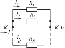
Fig. 8.7
U \u003d I total r total
where I general is the current of the current on the entire site, I general \u003d \u003d i 1 + i 2 + ... + I n; I 1 - current in the first conductor resistance R 1, I 1 \u003d U / R 1; I 2 - current power in the second conductor resistance R 2, I 2 \u003d U / R 2; ...; I n is the current force in the N -M conductor resistance R n, i n \u003d u / r n; R total - the overall resistance of the area defined by the formula
1 R total \u003d 1 R 1 + 1 R 2 + ... + 1 R n.
Example 6. The garland of 25 of the same light bulbs is included in the network with a voltage of 220 V and consumes current by force 25 A. Determine the resistance of one light bulb if they are turned on in parallel.
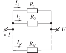
Decision . Light bulbs are connected in parallel, as shown in the figure. Light bulbs are the same:
R 1 \u003d R 2 \u003d ... \u003d R n \u003d r.
The total resistance of the chain is determined by the ratio
R common \u003d R n,
where R is the resistance of one light bulb (the desired value); N - the number of light bulbs.
According to the Ohm's law, the current strength in the chain is determined by the formula
I \u003d u r Society.
Substitute in the record law expression for general resistance
and express the desired resistance
R \u003d n u i.
Perform calculation:
R \u003d 25 ⋅ 220 25 \u003d 220 ohms.
The resistance of one light bulb is 220 ohms.
Example 7. The chain section consists of a resistor with a resistance of 4.0 Ohms included in series resistors with a resistance of 8.0 ohms and 16 ohms, which are interconnected in parallel. Determine the voltage on the 4-ohome resistor if the resistance resistance is 8.0 ohms flows the current by force 10 A.
Decision . The figure shows the circuit diagram on which the currents occur in the individual sections are indicated.
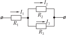
In the resistance area R 1 flows current I 1. Next, the current i 1 branches into two parts:
- in the area of \u200b\u200bresistance R 2 flows current I 2;
- at the resistance area R 3 flows current I 3.
In this way,
I 1 \u003d i 2 + i 3,
where i 2 is the current of the current in the 8-ohm resistor, I 2 \u003d 10 A.
The resistances of R 2 and R 3 are connected in parallel, so the voltage drops in the specified areas are the same:
I 2 R 2 \u003d i 3 R 3,
where R 2 \u003d 8.0 ohms; R 3 \u003d 16 Ohm.
Recorded equations form the system
I 1 \u003d i 2 + i 3, i 2 R 2 \u003d i 3 R 3,)
allows you to obtain a formula for calculating the current strength i 1 in a 4-ohm resistor:
I 1 \u003d i 2 (1 + R 2 R 3).
The desired voltage on the 4-ohm resistor is determined by the expression
U \u003d i 1 R 1 \u003d i 2 R 1 (1 + R 2 R 3),
where R 1 \u003d 4.0 Ohm.
Calculate:
U \u003d 10 ⋅ 4.0 (1 + 8.0 16) \u003d 60 V.
The area of \u200b\u200bthe chain, on which third-party forces do not apply, resulting in the occurrence of the electromotive force (Fig. 1), is called homogeneous.
Ohma law for a homogeneous segment of the chain was established experimentally in 1826 G. Omom.
According to this law, the current I current in a homogeneous metallic conductor is directly proportional to the voltage U at the ends of this conductor and inversely proportional to the resistance of the R of this conductor:
Figure 2 shows a scheme electrical chainallowing you to experimentally check this law. In a plot of MN, the chains alternately include conductors with various resistances.
The voltage at the ends of the conductor is measured by a voltmeter and can be changed using a potentiometer. The current strength is measured by an ammeter, the resistance of which is negligible (Ra ≈ 0). The graph of the current force in the conductor from the voltage on it is the volt-ampere characteristic of the conductor - is shown in Figure 3. The angle of inclination of the volt-amps characteristic depends on electrical resistance Explorer R (or its electrical conductivity G) :. ![]()
The resistance of the conductors depends on its size and shape, as well as on the material from which the conductor is made. For a homogeneous linear conductor, the resistance R is directly proportional to its length L and inversely proportional to the area of \u200b\u200bits cross section S:
where R is a proportionality coefficient characterizing the conductor material and called the specific electrical resistance. Unit of specific electrical resistance - Om × meter (Om × m).
30. Ohm law for an inhomogeneous section of the chain and for a closed chain.
When the electric current is passed in the closed chain on free charges, the power of the stationary electric field and third-party strength. At the same time, in some sections of this circuit, the current is created only by a stationary electric field. Such sections of the chain are called homogeneous. In some areas of this chain, in addition to the power of a stationary electric field, third-party forces act. A section of the chain on which third-party forces act is called an inhomogeneous section of the chain.
In order to find out what the current is depends on these sites, it is necessary to clarify the concept of voltage.
Consider at first a homogeneous section of the chain (Fig. 1, a). In this case, the work on the movement of charge makes only the forces of the stationary electric field, and this area is characterized by the difference in potentials Δφ. The potential difference at the ends of the site, where AK is the work of the forces of a stationary electric field. The inhomogeneous section of the chain (Fig. 1, b) contains, unlike a homogeneous site, the source of EDC, and to work forces electrostatic field On this site, the work of third-party forces is added. By definition, where q is a positive charge that moves between any two chain points; - the difference in potentials of points at the beginning and end of the section under consideration; . Then they talk about voltages for tension: Estent. e. P. \u003d EE / Stat. p. + Estor. The voltage U on the plot of the chain is a physical scalar valueequal to the total work of third-party strength and forces of the electrostatic field to move a single positive charge on this site:
From this formula, it can be seen that in general, the voltage in this section of the chain is equal to the algebraic amount of the potential difference and the EMF in this area. If only on the site is valid electric power (ε \u003d 0), then. Thus, only for a homogeneous section of the chain of the concept of voltage and the difference in potentials coincide.
Ohma law for an inhomogeneous section of the chain is:
where R is the overall resistance of the inhomogeneous site.
Electromotive force (EMF. ) ε can be both positive and negative. This is due to the polarity of inclusion electromotive force (EMF. ) In the section: If the direction generated by the current source coincides with the direction of the current passing in the area (the current direction on the site coincides inside the source with the direction from the negative pole to the positive), i.e. EMF contributes to movement positive charges In this direction, ε\u003e 0, otherwise, if the EMF prevents the movement of positive charges in this direction, then ε< 0.
31. Ohm's law in differential form.
Ohm's law for a homogeneous section of the chain, all points of which have the same temperature, is expressed by the formula (in modern notation):
In this form, the formula of the Ohm law is valid only for conductors eltimate lengthSince the magnitude of the value I and U included in this expression is measured by the instruments included in this area.
The resistance R section of the chain depends on the length L of this section, the cross section S and specific resistance Explorer ρ. The dependence of resistance from the material of the conductor and its geometric dimensions is expressed by the formula:
which is valid only for conductor of a permanent section. For variable section conductors, the corresponding formula will not be so simple. In the conductor of alternating section, the current strength in different sections will be the same, but the current density will be different not only in different sections, but even at various points of the same section. Intensity, and, therefore, the difference of potentials at the ends of various elementary sections will be different. The averaged values \u200b\u200bof I, U and R throughout the volume of the conductor do not provide information on the electrical properties of the conductor at each of its point.
To successfully study the electrical circuits, it is necessary to obtain an expression of the Ohm law in differential form so that it is performed at any point of the conductor of any shape and any sizes.
Knowing the connection of the electric field tension with the difference of potentials at the ends of a certain section, the dependence of the resistance of the conductor from its size and material and using the Ohm's law for a homogeneous section of the chain in integral form Find:
Denote by where σ is the specific electrical conductivity of the substance from which the conductor is made, we get:
where - current density. The current density is a vector, the direction of which coincides with the direction of the velocity vector of the movement of positive charges. The resulting expression in vector form will look:
It is performed at any point of the conductor through which the electric current flows. For a closed chain, it is necessary to take into account the fact that in it, in addition to the tension of the field of Coulomb forces, there are third-party forces that create a field of third-party strength, characterized by tensions eats. Taking into account this, the law of Oma for a closed circuit in differential form will look at:
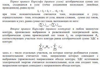
32. Branched electrical chains. Kirchhoff rules.
The calculation of branched chains is simplified, if you use Kirchhoff rules. The first rule refers to the chain nodes. The node is called a point in which more than two currents converges. The currents current to the node are considered to have one sign (plus or minus), from the node - have another sign (minus or plus).
The first Rule of Kirchhoff is an expression of the fact that in the case of the established direct current Neither at any point of the conductor and in any of its plot should not accumulate electrical charges and is formulated as follows: the algebraic amount of currents converging in the node is zero
The second rule of Kirchhof is a generalization of the Ohm's law on branched electrical chains.
Consider an arbitrary closed circuit in a branched chain (circuit 1-2-3-4-1) (Fig. 1.2). We will set the contour bypass clockwise and apply to each of the unbreakable areas of the circuit Ohm.
Moving these expressions, while the potentials are reduced and we obtain expression
In any closed circuit of an arbitrary branched electrical circuit, the algebraic amount of voltage drops (works of strength of currents for resistance) of the corresponding sections of this circuit is equal to the algebraic amount of EMF included in the contour.
33. Work and power of DC. Law of Joule Lenza.
Current operation - the operation of the electric field electrical charges along the conductor;
The current operation on the plot of the chain is equal to the product of the current, voltage and time during which the work was performed.
Using the formula of the Ohm law for the circuit section, you can write several options for the formula for calculating the current operation:
According to the law of energy conservation:
the work is equal to the change in the energy of the circuit section, so the energy provided by the conductor
equal to current operation.
In the SI system:
Law of Joles -Lenza
When current passes through the conductor, the conductor is heated, and heat exchange with the environment, i.e. The conductor gives warmth around his bodies.
The amount of heat released by the conductor with the current in environmentIt is equal to the product of the current of the current force, the resistance of the conductor and the passage time on the conductor.
According to the law of maintaining energy, the amount of heat released by the conductor is numerically equal to the work that the current flows through the conductor during the same time.
In the SI system:
DC power
The ratio of current operation during T to this time interval.
In the SI system:
34. Magnetic DC field. Power lines. Induction magnetic field in vacuum .
35. Law of Bio-Savara Laplas. The principle of superposition.
The Law of Bio-Savara Laplace for the conductor with current I, the element DL of which creates at some point A (Fig. 1) the induction of the DB field is equal to
where DL - vector, module equal to the length of the DL of the conductor element and the coincidence in the direction with the current, R is a radius-vector, which is carried out from the conductor DL \u200b\u200belement to the point A field, R is the radius-vector module R. Direction DB perpendicular to DL and R, i.e. perpendicular to the plane in which they lie, and coincides with the direction of tangent to the magnetic induction line. This direction can be found according to the rule of the right screw: the direction of rotation of the screw head gives the direction of DB if the progressive movement of the screw coincides with the direction of the current in the element.
DB vector module is set as expression
where α is the angle between the vectors of DL and R.
Similar to electrical, for the magnetic field is performed superposition principle: Magnetic induction of the resulting field created by several currents or moving charges is equal to a vector amount of magnetic induction of foldable fields created by each current or moving charge separately:
Using the data of the formula for the calculation of the characteristics of the magnetic field (B and H), in the general case is quite complicated. However, if the current distribution has any symmetry, the use of the BIO-Savara law - Laplace together with the principle of superposition makes it possible to simply calculate some fields.
36. Magnetic field of rectilinear conductor with current.
The magnetic induction lines of the magnetic field of rectilinear current are concentric circles located in a plane perpendicular to the conductor, with the center on the conductor axis. The direction of induction lines is determined by the rule of the right screw: if you rotate the screw head so that the progressive movement of the screw is taking place along the current in the conductor, the direction of rotation of the head indicates the direction of the magnetic induction of the direct conductor of the direct conductor.
Figure 1, and the straight conductor with a current is located in the pattern plane, induction lines - in the plane perpendicular to the figure. Figure 1, B depicted a section of the conductor, located perpendicular to the plane of the pattern, the current in it is directed from us (this is indicated by the cross "x"), the induction lines are located in the pattern plane.
As the calculations show, the magnetic induction module of the straight line can be calculated by the formula
where μ is the magnetic permeability of the medium, μ0 \u003d 4π · 10-7 H / A2 is the magnetic constant, I is the current of the current in the conductor, R is the distance from the conductor to the point in which the magnetic induction is calculated.
Magnetic permeability of the environment is physical quantityshowing how many times the magnetic induction module in the field in a homogeneous medium differs from the magnetic induction module B0 at the same point in the vacuum:
The magnetic field of the direct conductor with a current is an inhomogeneous field.
37. Magnetic field of circular turn with current.
According to the Bio-Savara-Laplace law, the induction of the magnetic field created by the DL current at a distance R from it is
where α is the angle between the current element and the radius-vector conducted from this element to the observation point; R is the distance from the current element to the observation point.
In our case α \u003d π / 2, sinα \u003d 1; where a is the distance countable from the center of the turn to the point under consideration on the axis of the turn. The vectors form at this point the cone with the angle of the solution at the vertex 2 \u003d π - 2β, where β is the angle between segments A and R.
For the considerations of symmetry, it is clear that the resulting magnetic field on the axis of the turn will be directed along this axis, that is, the contribution to it only the components that are parallel to the axis of the turn are given:
The resulting magnitude of the induction of the magnetic field B on the axis of the coat, we obtain, injecting this expression along the length of the contour from 0 to 2πr:
or, substituting the value of R:
In particular, at a \u003d 0 we find the induction of the magnetic field in the center of the circular turn with the current:
This formula can be given another form by using the magnetic moment determination of the turn with the current:
The last formula can be recorded in vector form (see Fig. 9.1):
38. The magnetic field action on the conductor with a current. Ampere Law.
The magnetic field acts with some force on any conductor with a current in it.
If the conductor in which the electrical current flows is suspended in a magnetic field, for example, between the magnet poles, the magnetic field will act on the conductor with some force and reject it.
The direction of movement of the conductor depends on the direction of current in the explorer and on the location of the magnet poles.
The force with which the magnetic field acts on the conductor with the current is called the force of the ampere.
The French physicist A. M. Ampere was the first to discovered the effect of the magnetic field on the conductor with a current. True, the source of the magnetic field in its experiments was not a magnet, but another conductor with a current. Placing conductors with a current next to each other, it discovered the magnetic interaction of currents (Fig. 67) - attraction of parallel currents and repulsion of anti-parallel (i.e. current in opposite directions). In the experiments of the ampere, the magnetic field of the first conductor operated on the second conductor, and the magnetic field of the second conductor is for the first one. In the case of parallel currents, the Ampere power turned out to be guided towards each other and the conductors were attracted; In the case of anti-parallel currents, the ampere strength changed their direction and the conductors were repelled from each other.
The direction of the amper power can be determined by the rule of the left hand:
if you arrange the left hand palm so that the four elongated fingers indicate the current direction in the conductor, and the power lines of the magnetic field were entered into the palm, then the retired thumb indicate the direction of force acting on the conductor with the current (Fig. 68).
This force (ampere power) is always perpendicular to the conductor as well power lines Magnetic field in which this conductor is located.
The amper power is not valid for any guide orientation. If the conductor with current to position along the si
The AMPER Act is the law of interaction of electrical currents. For the first time, Andre Marie Ampera in 1820 for DC was installed. From the AMPER law it follows that parallel conductors with electric currentsflowing in one direction are attracted, and in the opposite - repel. The AMPER's law is also called the law that determines the force with which the magnetic field acts on a small segment of the conductor with a current. The force with which the magnetic field acts on the element of the volume of the conductor with a density current located in a magnetic field with induction:
If the current flows on a thin conductor, then where the "length" element "of the conductor is the vector, the module is equal to the same and coinciding in the direction with the current. Then the previous equality can be rewritten as follows:
The force with which the magnetic field acts on the conductor element with a current located in a magnetic field is directly proportional to the current in the explorer and the vector product of the conductor length element for magnetic induction:
The direction of force is determined by the rule of calculation of the vector product, which is convenient to remember with the right hand rule.
Ampere power module can be found according to the formula:
where is the angle between magnetic induction and current vectors.
The power is maximal when the element of the conductor with current is located perpendicular to the magnetic induction lines
39. The interaction of rectilinear parallel currents.
The AMPER Act is used when the strength of the interaction of two currents is found. Consider two endless rectilinear parallel current I1 and I2; (Directions of currents are given in Fig. 1), the distance between which R. Each of the conductors creates a magnetic field around itself, which operates according to the AMPER's law to the adjacent conductor with a current. We find with which force the magnetic current of the current i1 is valid to the element DL of the second conductor with current I2. The magnetic field of current i1 is the magnetic induction lines, which are concentric circles. The direction of the vector B1 is set by the rule of the right screw, its module is
The direction of the DF1 force with which the B1 field acts on the second current DL section is located according to the rule of the left hand and is indicated in the figure. Module of force using (2), taking into account the fact that the angle α between the I2 current elements and the B1 line is equal to
substituting the value for B1, we find
Similarly, arguing, it can be shown that the power of DF2 with which the magnetic field of the current I2 acts on the element DL of the first conductor with a current I1, is directed in the opposite direction and the module is equal to
Comparison of expressions (3) and (4) gives that
i.e., two parallel current of the same direction are attracted to each other with force equal
If the currents have opposite directions, then using the rule of the left hand, we define that the repulsion force is used between the expression (5).
40. Magnetic field of driving electric charge.
Any conductor with a current creates a magnetic field in the surrounding space. In this case, the electric current is an ordered movement of electrical charges. So we can assume that any dwelling in a vacuum or medium is charged by a magnetic field around itself. As a result of the generalization of numerous experienced data, a law was established, which determines the field in point charge Q moving with a constant non-relativistic speed V. This law is defined by the formula
where R is a radius-vector, which is carried out from the charge Q to the point of observation M (Fig. 1). According to (1), the vector in is directed perpendicular to the plane in which the V and R vectors are located: its direction coincides with the direction of the transit movement of the right screw when it rotates from V to R.
Magnetic induction vector module (1) is on the formula
where α is the angle between vectors V and r.
Comparison of the Bio-Savara-Laplace law and (1), we see that a moving charge on its magnetic properties is equivalent to an current element:
These laws (1) and (2) are performed only at low speeds (V<<с) движущихся зарядов, когда электрическое поле движущегося с постоянной скорость заряда можно считать электростатическим, т. е. создаваемым неподвижным зарядом, который находится в той точке, где в данный момент времени находится движущийся заряд.
Formula (1) sets the magnetic induction of a positive charge moving at a speed V. When moving, the negative charge Q is replaced by -Q. Speed \u200b\u200bV - relative speed, i.e. speed relative to the observer reference system. The vector in this reference system depends both on time and from the location of the observer. Therefore, it should be noted the relative nature of the magnetic field of the moving charge.
41. The theorem on the circulation of the magnetic field induction vector.
Suppose in the space where the magnetic field is created, some conditional closed loop (not necessarily flat) is selected and a positive direction of circuit crawl is indicated. At each single small section ΔL of this circuit, the tangent component of the vector in this place can be determined, that is, to determine the projection of the vector to the direction of the tangent to this section of the circuit (Fig. 4.17.2). 2.
Figure 4.17.2. Closed circuit (L) with a given bypass direction. Show currents I1, I2 and I3, creating a magnetic field.
The circulation of the vector is called the amount of products ΔL, taken over the entire contour L:
Some currents that create a magnetic field can permeate the selected circuit L while other currents can be located on the contour. The circulation theorem argues that the circulation of the vector of the magnetic field of constant currents according to any contour L is always equal to the product of the magnetic constant μ0 in the amount of all currents that penetrate the contour:
As an example in Fig. 4.17.2 depicts several conductors with currents creating a magnetic field. The currents of the I2 and I3 permeate the contour L in opposite directions, they must be attributed to different signs - the currents are considered positive, which are associated with the selected direction of circuit bypassing the rule of the right screw (a bull). Therefore, i3\u003e 0, and i2< 0. Ток I1 не пронизывает контур L. Теорема о циркуляции в данном примере выражается соотношением:
The circulation theorem in general follows from the law of Bio-Savara and the principle of superposition. The simplest example of the application of the circulation theorem is to determine the magnetic induction of the directing conductor field with the current. Considering the symmetry in this problem, the contour L is advisable to choose in the form of a circle of some radius R, lying in the perpendicular conductor of the plane. The center of the circle is at some point of the conductor. By virtue of symmetry, the vector is directed along the tangent (), and its module is the same in all points of the circle. The use of circulation theorem leads to the relation:
from where it follows the formula for the magnetic induction module of the straight conductor field with a current shown earlier. This example shows that the magnetic induction vector circulation theorem can be used to calculate the magnetic fields created by the symmetric distribution of currents, when the general structure of the field can be "guess" from symmetry considerations. There are quite a few practically important examples of calculating magnetic fields using the circulation theorem. One such example is the task of calculating the field of the toroidal coil (Fig. 4.17.3).
Figure 4.17.3. The use of the circulation theorem to the toroidal coil.
It is assumed that the coil is tight, that is, the turn to the turn is wound on a non-magnetic toroidal core. In such a coil, the magnetic induction line is closed inside the coil and are concentric circles. They are sent in such a way that looking along them, we would see the current in the turns circulating clockwise. One of the lines of induction of some radius R1 ≤ R< r2 изображена на рис. 4.17.3. Применим теорему о циркуляции к контуру L в виде окружности, совпадающей с изображенной на рис. 4.17.3 линией индукции магнитного поля. Из соображений симметрии ясно, что модуль вектора одинаков вдоль всей этой линии. По теореме о циркуляции можно записать:B ∙ 2πr = μ0IN,
where N is the total number of turns, and the I - the current, the current coils. Hence,
Thus, the magnetic induction vector module in a toroidal coil depends on the R radius. If the core coil is thin, that is, R2 - R1<< r, то магнитное поле внутри катушки практически однородно. Величина n = N / 2πr представляет собой число витков на единицу длины катушки. В этом случае B = μ0In.
42. Magnetic field of an infinite rectilinear conductor with a current and infinitely long solenoid.
Each part of the toroidal coil can be viewed as a long straight coil. Such coils are called solenoids. Different from the solenoid ends, the magnetic induction module is expressed by the same relation as in the case of a toroidal coil. In fig. 4.17.4 shows the magnetic field of the finite length coil. It should be paid to the fact that in the central part of the coil the magnetic field is almost uniform and much stronger than outside the coil. This indicates the thickness of magnetic induction lines. In the limit case of an infinitely long solenoid, a homogeneous magnetic field is entirely focused inside the solenoid.
Figure 4.17.4. Magnetic field of the ultimate coil. In the center of the solenoid, the magnetic field is almost uniform and significantly exceeds the module field outside the coil.
In the case of an infinitely long solenoid, the expression for the magnetic induction module can be obtained directly using the circulation theorem by applying it to the rectangular contour shown in Fig. 4.17.5.
Figure 4.17.5. The use of the circulation theorem to the calculation of the magnetic field of an infinitely long solenoid.
The magnetic induction vector has a non-zero projection on the ABCD contour bypass direction only on the AB side. Consequently, the circulation of the vector along the contour is equal to BL, where L is the length of the AB side. The number of spikes of the solenoid, penetrating the ABCD circuit, is N · L, where n is the number of turns per unit of the length of the solenoid, and the full current, penetrating the contour, is inL. According to the circulation theorem, BL \u003d μ0INL,
Where b \u003d μ0in.
43. Magnetic field induction flow. Ostrogradsky-Gaus theorem for magnetic field.
A vector stream of magnetic induction (magnetic flow) through the DS area is called a scalar physical value that is equal to
where Bn \u003d Bcosα is the projection of the vector in the direction of normal to the DS site (α - the angle between the vectors N and C), DS \u003d DSN - the vector in which the module is equal to DS, and its direction coincides with the direction of normal N to the platform. The flow stream in can be both positive and negative depending on the COSα sign (set by the choice of the positive direction of normal N). The stream of the vector is usually associated with the contour by which the current flows. In this case, the positive direction of normal to the contour we wondered: it binds to the current rule of the right screw. It means that the magnetic flow, which is created by the contour, through the surface limited to them itself is always positive.
The flow of the magnetic induction of FB through an arbitrary specified surface s is equal
For a homogeneous field and a flat surface, which is located perpendicular to the vector B, BN \u003d B \u003d const and
From this formula, the unit of magnetic flux of Weber (WB) is set: 1 WB is a magnetic stream, which passes through the flat surface of 1 m2, which is located perpendicular to a homogeneous magnetic field and the induction of which is 1 TL (1 W \u003d 1 TL M2).
The Gaussian Theorem for the field in: vector flow of magnetic induction through any closed surface is zero:
This theorem is a reflection of the fact that the magnetic charges are absent, as a result of which the magnetic induction line has no beginning, no end and are closed.
Consequently, for the streams of vectors in and e through the closed surface in the vortices and potential fields, various formulas are obtained.
As an example, we will find the flow of the vector through the solenoid. The magnetic induction of a homogeneous field inside a solenoid with a core with a magnetic permeability μ, equal
Magnetic stream Through one round of Solenoid Snemide S is equal
a full magnetic flux that is connected to all solenoid turns and called streaming,
44. The operation of moving the conductor and circuit with a current in a magnetic field.
Consider the circuit with a current formed by stationary wires and moving along it a movable jumper L (Fig. 2.17). This outline is in an external homogeneous magnetic field perpendicular to the contour plane. As shown in the figure, the current direction I, the vector is co-directed with.
On the current I (movable wire) Length L, the ampere force is directed to the right:
Let the conductor L move parallel to itself at the distance dx. At the same time work work:
The work performed by the conductor with the current when moving is numerically equal to the product of the current on the magnetic flux crossed by this conductor.
The formula remains fair if the conductor of any shape moves at any angle to the magnetic induction vector lines.
We will withdraw an expression to work on moving a closed loop with a current in a magnetic field.
Consider a rectangular circuit with a current of 1-2-3-4-1 (Fig. 2.18). The magnetic field is directed from us perpendicular to the contour plane. The magnetic stream, piercing the contour, is directed along the normal to the contour, therefore.
We move this outline in parallel to myself in a new position 1 "-2" -3 "-4" -1 ". The magnetic field in the general case can be inhomogeneous and the new circuit will be permeated with a magnetic flow.
The site 4-3-2 "-1" -4, located between the old and new circuit, is permeated by the stream.
Full work on the movement of the contour in a magnetic field is equal to the algebraic amount of work performed when moving each of the four sides of the circuit:
where, equal to zero, because These parties do not intersect the magnetic flux, with their movement (delineate the zero area).
Wire 1-2 cuts stream (), but moves against the forces of the magnetic field.
Then the overall work on the movement of the contour
here is a change in the magnetic flux captured with the contour.
The work performed when moving the closed circuit with a current in a magnetic field is equal to the product of the current to change the magnetic flux, linked to this circuit.
Elementary work on infinitely small displacement of the circuit in a magnetic field can be found by the formula
Electromotive force.
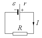
Ohm's law for a closed chain and an inhomogeneous section of the chain.
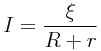
Ohm's law for a closed chain says that. The value of the current in the closed circuit, which consists of a current source with internal resistance, as well as external load resistance. It will be equal to the ratio of the electromotive force of the source to the sum of external and internal resistance.
Ohm law for heterogeneous section of chain
When the electric current is passed in the closed circuit on free charges, the forces on the part of the stationary electric field and third-party power are used. At the same time, in some sections of this circuit, the current is created only by a stationary electric field. Such sections of the chain are called homogeneous. In some areas of this chain, in addition to the power of a stationary electric field, third-party forces act. A section of the chain on which third-party forces act is called an inhomogeneous section of the chain.
In order to find out what the current is depends on these sites, it is necessary to clarify the concept of voltage.
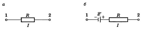
Fig. one
Consider at first a homogeneous section of the chain (Fig. 1, a). In this case, the work on the movement of charge makes only the forces of the stationary electric field, and this area is characterized by the difference in potentials Δφ. Potential difference at the ends of the site ![]() Where AK is the work of the powerful electric field forces. The inhomogeneous section of the chain (Fig. 1, b) contains as opposed to a homogeneous section of the source of EDC, and the work of third-party forces is added to the operation of the electrostatic field forces. By definition, where q is a positive charge that moves between any two chain points; - the difference in potentials of points at the beginning and end of the section under consideration; . Then they talk about voltages for tension: Estent. e. P. \u003d EE / Stat. p. + Estor. The voltage U on the circuit site is a physical scalar value equal to the total work of third-party forces and forces of the electrostatic field to move a single positive charge on this site:
Where AK is the work of the powerful electric field forces. The inhomogeneous section of the chain (Fig. 1, b) contains as opposed to a homogeneous section of the source of EDC, and the work of third-party forces is added to the operation of the electrostatic field forces. By definition, where q is a positive charge that moves between any two chain points; - the difference in potentials of points at the beginning and end of the section under consideration; . Then they talk about voltages for tension: Estent. e. P. \u003d EE / Stat. p. + Estor. The voltage U on the circuit site is a physical scalar value equal to the total work of third-party forces and forces of the electrostatic field to move a single positive charge on this site:
![]()
From this formula, it can be seen that in general, the voltage in this section of the chain is equal to the algebraic amount of the potential difference and the EMF in this area. If only electrical strength (ε \u003d 0) act on the site (ε \u003d 0), then. Thus, only for a homogeneous section of the chain of the concept of voltage and the difference in potentials coincide.
Ohma law for an inhomogeneous section of the chain is:
![]()
where R is the overall resistance of the inhomogeneous site.
EMF ε can be both positive and negative. This is due to the polarity of the inclusion of EMF in the area: if the direction generated by the current source coincides with the direction of the current passing in the site (the current direction on the site coincides inside the source with the direction from the negative pole to the positive), i.e. EMF contributes to the movement of positive charges in this direction, then ε\u003e 0, otherwise, if the EMF prevents the movement of positive charges in this direction, then ε< 0.
Rules of Kikhhof.
Work and current power. Thermal current. Law of Joule Lenza.
When current flows over a homogeneous section of the chain, the electric field makes a job. During the time Δ t, the chain flows Δ q \u003d i Δ t. The electric field on the highlighted hassle makes the work
The power of the electric current is equal to the ratio of the current Δ A by the time interval Δ T, for which this work was performed:
The operation of electric current in Si is expressed in Joules (J), power - in watts (W).
Consider now the complete chain of a DC, consisting of a source with an electromotive force and the inner resistance of R and an external homogeneous area with the resistance R. Ohm's law for the total chain is recorded as
The first term in the left part of Δ q \u003d R i 2 Δ T is a heat released on the external section of the chain during the Δ T, the second term Δ q East \u003d R i 2 Δ T is the heat released inside the source during the same time.
The expression I Δ T is equal to the work of the third-party forces Δ A st, acting within the source.
When the electric current of the closed circuit is flowing, the operation of third-party forces Δ A article is converted to a heat released in the outer chain (Δ q) and inside the source (Δ q East).
|
It should be noted that this ratio does not include the operation of the electric field. When the current flow across the closed circuit, the electrical field of operation does not perform; so heat is made only by third-party forces.acting inside the source. The role of the electric field is reduced to the redistribution of heat between different parts of the chain.
The outer chain can be not only a conductor with resistance R, but also any device that consumes power, for example, a DC motor. In this case, under R need to understand Equivalent load resistance. The energy highlighted in the outer chain can be partially or completely converted not only to heat, but also to other types of energy, for example, in the mechanical work performed by the electric motor. Therefore, the question of using the energy source energy is of great practical importance.
Full-text search:
Home\u003e Abstract\u003e Industry, production
Ohm law for an inhomogeneous section of the chain.
To occur in the electrical current conductor, it is necessary that the electrical field existed inside the conductor, the sign of which is the presence of potential difference at the ends of the conductor.
Create an electric field in an electrical circuit can be at the expense of the charges available in it. To do this, it is enough to divide the charges of opposite signs, focusing in one area of \u200b\u200bthe chain an excessive positive charge, in the other - negative (to create noticeable fields, it is enough to share a negligible part of charges).
The separation of multi-dimensional charges cannot be carried out by the power of electrostatic (Coulomb) interaction, since these forces not only do not disconnect, but on the contrary, they seek to connect the charges of opposing signs, which inevitably leads to equalization of potentials and the disappearance of the field in conductors. The separation of multimenamic charges in the electrical circuit can be carried out only by non-electrical origin.
Forces separating charges in the electrical circuit, creating an electrostatic field in it, are called third-party.
Devices in which third-party power are called sources of current.
The nature of third-party strength may be different. In some sources, these forces are due to chemical processes (galvanic elements), in other - diffusion of charge carriers and contact phenomena (contact EDC), in the third - the presence of a vortex electric field (electrical generators), etc. Third-party forces act on charges only in current sources, and there they act either all the ways of following charges through the source or in some sections. In this regard, they talk about sources with distributed and focused third-party forces. An example of a source with distributed third-party forces can be an electrical generator - in it these forces act on the entire length of the anchor winding; An example of a source with focused third-party forces can be a galvanic element - in it these forces act only in the finest layer adjacent to the electrodes.
Since third-party valid only in the source, but electrostatic - and in the source and in the external chain, then there are areas in any chain, where third-party and electrostatic forces are also operating on charges. A plot of chain in which only electrostatic forces act on charges is called, as already mentioned, uniform. The plot in which electrostatic, and third-party power are also operating on charges inhomogeneous. In other words, a non-uniform area is a plot containing the current source.
When moving charges for such a plot, electrostatic and third-party forces make work. Third-party work characterizes electromotive force (Abbreviated EDC).
The electromotive force on this section of the chain 1-2 is called a scalar physical value, numerically equal to the work performed by third-party forces when moving a single, positive point charge from point 1 to point 2
The work of electrostatic forces characterizes potential difference.
The potential difference between points 1 and 2 of the electrical circuit is called a scalar physical quantity, numerically equal to the operation performed by electrostatic forces when moving a single, positive point charge from point 1 to point 2
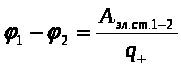 .
.
The joint work of third-party and electrostatic forces on this section of the chain characterizes the voltage.
The voltage in this section 1-2 is the physical quantity, numerically equal to the algebraic amount of work performed by electrostatic and third-party forces when moving a single, positive point charge from the point1 exactly2 .
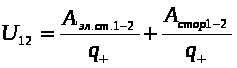 .
.
Or, in other words, ![]() .
.
If the resistance of the inhomogeneous site 1-2 Equally, the current flows I. , Taking advantage of the law of conservation of energy, it is possible to obtain the law of Oma for the inhomogeneous section of the chain.
If the current in the chain is stationary, the plot of the chain is still not changed and its temperature does not change, the only result of the current operation on this site will be the highlight of heat to the environment. Complete operation of current, folding from the works of electrostatic and third-party forces, during t. equal to the number of heat excreted.
and ![]() .
.
Then, and after cuts
![]() .
.
From here  - Ohm law for an inhomogeneous section of the chain in the integral form: the strength of the current in the inhomogeneous section of the electrical value is directly proportional to the algebraic amount of the potential difference at the ends of the section and the EMF, acting in this section, and inversely proportional to the full resistance of the site.
The strength of the current, the difference of potentials and the EMF in this formula is the magnitude of algebraic. Their sign depends on the direction of parting the site. If the direction of the current coincides with the direction of bypass, it is considered positive. If the current source sends a current in the direction of bypass, its EMF is considered positive. The following is an example of the entry of the Ohm law for an inhomogeneous section of the chain shown in Fig. 52.
![]()
When bypass from a to  ,
,
from in to a  .
.
That is, when changing the direction of bypass, all the values \u200b\u200bincluded in the Ohm law change the sign.
Thus, the law of Oma and for homogeneous and for inhomogeneous sites is one of the manifestations of the law of conservation and turning the energy.
4.5. The consequences of the Ohm law for the inhomogeneous section of the chain.
Consider the consequences arising from the Ohm law for the inhomogeneous section of the chain.
1. If there is no current source in this section (
12
=0
), then we get the law of Oma for a homogeneous site 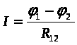 ,
,
from where it follows that ![]() or
or ![]() .
.
The voltage and the difference of potentials on a homogeneous section of the chain are equal to each other.
 2. If you consider a closed chain, then or. Substituting it in the original formula, we get
where
![]() - full chain resistance- resistance to the outer section of the chain, - resistance of the inner portion of the chain (current source).
- full chain resistance- resistance to the outer section of the chain, - resistance of the inner portion of the chain (current source).
![]() Then.
Then.
The strength of the current in a closed circuit is directly proportional to the EMF and inversely proportional to the full chain resistance- Ohm's law for the full chain.
3. If the circuit is open, there is no current in it ( I.=0 ) IR.=0 .
Then ![]() , i.e EMF is equal in absolute value and is opposite to the sign of the potential difference at the clips of the open source.
, i.e EMF is equal in absolute value and is opposite to the sign of the potential difference at the clips of the open source.
4.6. Power in DC circuit.
The power of the electric current on a homogeneous area of \u200b\u200bthe chain with resistance is sufficiently simple can be found as the ratio of the work performed by the electrostatic field to move in charges of charges by the time for which this work is performed:
In this way, the power of the electric current on the circuit section is proportional to the square of the current strength and the resistance of the site.
If you consider a closed chain (Fig. 53), then in such a chain it is customary to consider two types of power - complete and useful. Full Called the power that stands out throughout the circuit, that is, both on the external resistance and on the internal resistance of the current source. Then complete power can be found as a product of the current of the current for the total chain resistance:
![]() , and using the Ohm law for a closed chain, we get:
, and using the Ohm law for a closed chain, we get:
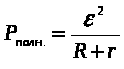 .
.
Useful call the power that stands out on the external resistance of the chain, that is, it is equal ![]() And again applies the Ohm law for a closed chain, we get:
And again applies the Ohm law for a closed chain, we get: 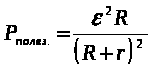 .
.
Efficient efficiency (efficiency) a closed chain call the ratio of useful power to full. Using the derived formulas, we get:
![]()
We find out how useful, full power and efficiency depend on the resistance of the external chain. It can be seen that the complete power is maximal when and decreases with increasing external resistance. Useful power at first increases from zero to some value, and then decreases with growth. To find out with what value the useful power is maximal, it is necessary to equate to zero derivative.
 from here after cutting we get
Thus, the maximum power in the outer chain develops, provided that the resistance of the outer chain is equal to the internal resistance of the current source. We note that with this condition, the efficiency is only 0.5, that is, only half of the power developed by the source of the current is released in the outer chain, the remaining power goes to heating the source itself. 
![]()
In fig. 54 graphically depicts the dependences of complete and useful power, as well as the efficiency for a closed chain from the external resistance of the chain.
Bibliographic list
Savelyev I.V. Course of general physics: T.2. Electricity. - M.: Science, 1987. - 432 p.
Trofimova T.I. Course of physics: studies. Handbook for universities. - 7th ed., Ched. - M.: Higher. School, 2003. - 542 C.: IL.
Detlaf F.F., Yavorsky B.M. Course of physics: studies. Handbook for themp. - M.: Science, 1989. - 608 p.
Preface .......................................................................................... 3
1. Electric field in vacuum .................................................................. 4
1.1. Electromagnetic field - material carrier
electromagnetic interaction .................................................... 4
1.2. Electric charges ............................................................... .......
1.3. Cut law ............................................................... ..................... 5
1.5. Principle of superposition of fields ............................................................. 7
1.6. Calculation of electric fields based on the principle of superposition ............... 8
1.7. Lines of tension vector ...................................................... ..10
1.8. Stream vector of tension ...................................................... ... 11
1.9. Gaussian theorem ................................................................................ 13
1.10. The use of the Gauss Theorem to the calculation of electric fields .................12
1.11. Work of the power of the electrostatic field .............................. ..................... 18
1.12. Circulation of the tension of the electrostatic field ......... ...... 19
1.13. The potential of the electrostatic field ................................. ................. 20
1.14. Communication between the tension and the potential of the electrostatic field..21
1.15. Calculation of the potential and potential difference in the electrostatic field ... 23
2. Electric field in dielectrics ................................................................. ... 24
2.1. Conductors, dielectrics, semiconductors .................................... ... 24
2.2. Polarization of dielectrics ............................................................ 25
2.3. Polarization types .......................................................................26
2.4. The relationship of the values \u200b\u200bcharacterizing polarization ............ ................. 28
2.5. Electric field in dielectrics .................................... ................. 29
2.6. Vector of electrical displacement ....................................... ................. 30
2.7. Calculation of the electric field in the presence of dielectrics ........................ 33
2.8. Segnetoelectrics ........................................................................ 33.
2.9. Piezoelectric effect. Electrotrix ................................. ... 35
3. Conductors in the electric field. Electric field energy ................36
3.1. Distribution of charges on the conductor ................................. .................. 36
3.2. Explorer in an external electric field .................................... ... 38
3.3. Conductor electrical capacity ......................................................... 39
3.4. Mutual electrical capacity. Condenters .......................................... 40.
3.5. Constressor connection ............................................................ 41
3.6. Energy of the system of fixed point charges .................. ................. 42
3.7. Own energy charged conductor and condenser ............... 43
3.8. Energy electric field ......................................................................... 44
4. DC laws .................................................................. .45
4.1. The concept of electric current ...................................................... 45
4.2. Ohm's law for a homogeneous section of the chain ....................................... ... 47
Always closed, ... Lecture \u003e\u003e Natural science
No missing. Present course Deals with modern concepts ... The magnetostatic field is generated permanent tokami, the existence of which ... Unlike elektostatiki, consistent the theory of magnetic ... conducting review lectures- Discussions after ...
Methods of application of the COR in the process of studying the topic Electromagnetic oscillations
Coursework \u003e\u003e PedagogyThermodynamics and molecular physics, electrostatics, optics, atomic and nuclear ... Number of experimental materials. Course "Open Physics 2.0" ... the law established for permanent tok, to describe processes ... Developed in the form lecturessince this ...
8.3. Ohm's law
8.3.2. Ohma law for inhomogeneous plot and for complete chain
The electromotive force (EMF) of the source is numerically equal to the work performed by third-party forces on the movement of a single positive charge, and is determined by the ratio:
ℰ \u003d A ST Q,
where a st is the work of third-party forces (forces of non-flavored origin) to move the charge Q.
In the international system units, the electromotive force (EMF) is measured in volts (1 V).
The area of \u200b\u200bthe chain is called inhomogeneous (Fig. 8.8), if it includes the source EMF, i.e. There are third-party strength on it.
Fig. 8.8.
Ohm law for heterogeneous section of chain It has the following form:
I \u003d φ 2 - φ 1 + ℰ R + R,
where I is the current strength; φ 1 - Potential point A; φ 2 - Potential point B; ℰ - EDF of the current source; R is the resistance of the site; R is the internal resistance of the current source.
Full (closed) chain is depicted in fig. 8.9.
Fig. 8.9
Points A and B are indicated by the EMF source terminals. The closed circuit can be divided into two sections:
- internal - a plot containing the source of EDC;
- external - a plot that does not contain the source of the EDC.
Electric current direction:
- in the inner chain - from "minus" to "plus";
- in the external chain - from the "plus" to "minus".
The strength of the current in a complete (closed) chain (see Fig. 8.9) is determined by the Ohm's law (the current in the closed chain containing the current source is directly proportional to the electromotive strength of this source and is inversely proportional to the sum of external and internal resistances):
I \u003d ℰ R + R,
where I is the current strength; ℰ - the electromotive force (EMF) of the source, ℰ \u003d a st / q; A ST - the work of third-party strength (forces of non-flaunt origin) to move the positive charge Q; R is an external chain resistance (load); R is the internal resistance of the current source.
Fig. 8.9
The electromotive force (EMF) of the current source in a closed circuit is the amount
ℰ \u003d IR + IR,
where IR is a drop in voltage (potential difference) at the external section of the chain; IR - voltage drop in the source; I - current strength; R is an external chain resistance (load); R is the internal resistance of the current source.
The reduced equation recorded in the form
ℰ - IR \u003d IR,
specifies to equality potential differences on current source terminals U r \u003d ℰ - IR and potential differences on the external section of the chain U R \u003d IR, i.e.
U r \u003d u r.
Short circuit In the total chain, if the load in the outer chain is absent, i.e. The external resistance is zero: r \u003d 0.
Short circuit current I is determined by formula
Example 8. EMF of the current source is 18 V. The resistor is connected to the source, the resistance of which is 2 times the internal resistance of the source. Determine the potential difference at the current source clips.
Decision . The potential difference at the source clips is determined by the formula
U \u003d ℰ - IR,
where ℰ is the EMF of the current source; I - the power of the current in the chain; R is the internal resistance of the current source.
The strength of the current is determined by the Ohm's law for the total chain:
I \u003d ℰ R + R,
We substitute this expression in the formula for calculating the potential difference at the source clips:
U \u003d ℰ - ℰ R + R \u003d ℰ (1 - R R + R) \u003d ℰ R + R.
Taking into account the relationship between resistance resistor and source (R \u003d 2R) we obtain
U \u003d 2 ℰ 3.
The calculation gives the value:
U \u003d 2 ⋅ 18 3 \u003d 12 V.
The potential difference at the source clips is 12 V.
Example 9. The internal resistance of the battery is 1.5 ohms. When the resistor is closed on the resistor, the resistance of 6.0 ohms battery of elements gives a current by force 1.0 A. Find strength of a short circuit current.
Decision . The short circuit current is determined by the formula
where ℰ is the EMF of the current source; R is the internal resistance of the current source.
According to the law of Ohm for the full chain,
I \u003d ℰ R + R,
where R is the resistance of the resistor.
Express from the recorded formula of the Source EMF and substitute for a short circuit current expression:
i \u003d i (R + R) R.
Calculate:
i \u003d 1.0 ⋅ (6.0 + 1.5) 1.5 \u003d 5.0 A.
The short circuit current for the source with the specified values \u200b\u200bof the EMF and internal resistance is 5.0 A.
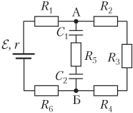
Example 10. Six identical resistors of 20 ohms each are connected to the circuit as shown in the figure. To the ends of the site are connected to a source with an emf equal to 230 V, and an internal resistance of 2.5 ohms. Find an Ampmeter AM readings.
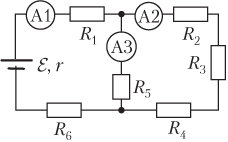
Decision . In fig. And the circuit is shown on which the currents flowing into its separate areas are indicated.
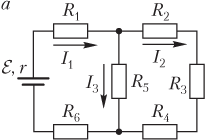
In the resistance area R 1 flows current I 1. Next, the current i 1 branches into two parts:
- on a plot with series connected resistors R 2, R 3 and R 4 flows current I 2;
- on the resistance area R 5 flows current I 3.
In this way,
I 1 \u003d i 2 + i 3.
These areas are interconnected in parallel, so the voltage drops on them are the same:
I 2 Rs 2 \u003d i 3 R 5,
where R is common - the resistance of the section with successively connected resistors R 2, R 3 and R 4, R Ohch2 \u003d R 2 + R 3 + R 4 \u003d 3R, R 2 \u003d R 3 \u003d R 4 \u003d R, R 5 \u003d R.
Recorded equations form the system:
I 1 \u003d i 2 + i 3, i 2 R total 2 \u003d i 3 R 5. )
Taking into account the expressions for R Ohch2 and R 5, the system takes the form:
I 1 \u003d i 2 + i 3, 3 i 2 \u003d i 3. )
Solution of the system relative to the current strength i 2 gives
I 2 \u003d i 1 4 \u003d 0.25 i 1.
This expression determines the desired value - the current strength in the AM ammeter A2.
The strength of the current i 1 is determined by the law of Ohm for the full chain:
I 1 \u003d ℰ R common + R,
where R total is the overall resistance of the external chain (resistors R 1, R 2, R 3, R 4, R 5 and R 6).
Calculate the overall resistance of the external chain.
To do this, we transform the scheme as shown in Fig. b.
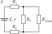
Sections R Ohch2 and R 5 are connected in parallel, their overall resistance
R total 1 \u003d R total 2 R 4 R total 2 + R 4 \u003d 3 R 4 \u003d 0.75 R,
where R is 2 \u003d 3r; R 4 \u003d R.
Once again we transform the scheme as shown in Fig. in .
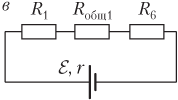
Plots of resistances R 1, R total1 and R 6 are connected consistently, their overall resistance
R total \u003d R 1 + R total 1 + R 6 \u003d R + 0.75 R + R \u003d 2.75 R,
where R is 4 \u003d 0.75r and R 1 \u003d R 6 \u003d R.
The desired current is determined by the formula
I 2 \u003d 0.25 i 1 \u003d 0.25 ℰ 2.75 R + R.
Calculate:
I 2 \u003d 0.25 ⋅ 230 2.75 ⋅ 20 + 2.5 \u003d 1.0 A.
AMPERMETER A2 will show current strength 1.0 A.
Example 11. Six identical resistors for 20 ohms each and two capacitors with electrical circuits 15 and 25 μF are connected to the circuit as shown in the figure. To the ends of the site are connected to a source with EDC, equal to 0.23 kV, and an internal resistance of 3.5 ohms. Find the potential difference between the edges of the second capacitor.
Decision . Between points A and B does not flow, as capacitors are included between these points in the circuit. To determine the difference in potentials between the specified points simplifies the scheme, excluding the part of the AB.
In fig. And the scheme of a simplified chain is shown.
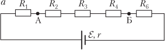
The current flows through the resistors R 1, R 2, R 3, R 4 and R 6, connected in series. General resistance of such a chain:
R general \u003d R 1 + R 2 + R 3 + R 4 + R 6 \u003d 5R,
where R 1 \u003d R 2 \u003d R 3 \u003d R 4 \u003d R 6 \u003d R.
The strength of the current I is determined by the Ohm's law for the total chain:
I \u003d ℰ R common + r \u003d ℰ 5 R + R,
where ℰ is the EDC of the current source, ℰ \u003d 0.23 kV; R is the internal resistance of the current source, R \u003d 3.5 ohms; R total - the overall chain resistance, R common \u003d 5r.
Calculate the drop in voltage between points A and B.
Between points A and B are resistors resistances R 2, R 3 and R 4, interconnected in each other, as shown in Fig. b.
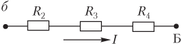
Their overall resistance
R Ohch1 \u003d R 2 + R 3 + R 4 \u003d 3R.
The voltage drop on these resistors is determined by the formula
U ab \u003d IR general1,
or explicitly -
U ab \u003d 3 ℰ R 5 R + R.
Between points A and B included the capacitor battery C 1 and C 2, interconnected between each other, as shown in Fig. in .
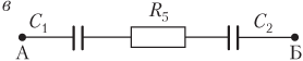
Their total electrical capacity
C total \u003d C 1 C 2 C 1 + C 2,
where C 1 is the electrical capacity of the first capacitor, C 1 \u003d 15 μF; C 2 - electrical capacity of the second capacitor, C 2 \u003d 25 μF.
Potential differences on battery plates:
U common \u003d Q c total,
where Q is the charge on the plates of each of the capacitors (coincides with the charge of the battery with a consecutive connection of the capacitors), q \u003d \u003d C 1 U 1 \u003d C 2 U 2; U 1 - the potential difference between the edges of the first capacitor; U 2 is the potential difference between the plates of the second capacitor (the desired value).
In an explicit form, the potential difference between capacitor clamps is determined by the formula
U SURE \u003d C 2 U 2 C total \u003d (C 1 + C 2) U 2 C 1.
The voltage drop on the resistors between points A and B coincides with the potential difference on the capacitors battery connected to the specified points:
U ab \u003d u common.
This equality recorded explicitly
3 ℰ R 5 R + R \u003d (C 1 + C 2) U 2 C 1,
allows you to obtain an expression for the desired value:
U 2 \u003d 3 ℰ R C 1 (5 R + R) (C 1 + C 2).
Calculate:
U 2 \u003d 3 ⋅ 0.23 ⋅ 10 3 ⋅ 20 ⋅ 15 ⋅ 10 - 6 (5 ⋅ 20 + 3.5) (15 + 25) ⋅ 10 - 6 \u003d 50 V.
Between the plates of the second capacitor, the potential difference is 50 V.


