8.3. Ohm's law
8.3.2. Ohma law for inhomogeneous plot and for complete chain
Electromotive force (EMF) of the source is numerically equal to the work performed by third-party forces on the movement of a single positive charge, and is determined by the ratio:
ℰ \u003d A ST Q,
where a st is the work of third-party forces (forces of non-flavored origin) to move the charge Q.
On the other hand, it is an excellent source of pure heat, because it converts approximately 80% -90% of energy consumed in heat, and the rest is visible light. Reflective lamp regardless of the concept of construction and operation of the lamp, the lamp industry has adapted some of the concepts of various lamps for reflective versions. In fact, it is enough to "cover" the lamp by blowing or extruded glass in a conical or a decayriconic format with an internal reflective material to ensure the effect of the projection of light.
In the international system units, the electromotive force (EMF) is measured in volts (1 V).
The area of \u200b\u200bthe chain is called inhomogeneous (Fig. 8.8), if it includes the source EMF, i.e. There are third-party strength on it.
Fig. 8.8.
Ohm law for heterogeneous section of chain It has the following form:
I \u003d φ 2 - φ 1 + ℰ R + R,
where I is the current strength; φ 1 - Potential point A; φ 2 - Potential point B; ℰ - EDF of the current source; R is the resistance of the site; R is the internal resistance of the current source.
Thanks to this art, the lamps acquire a greater force of light, with an increase in significant yields. Bandwidth. Transport transmission capacity over the transmission channel measured in bits or bytes per second. Ohma law is used to calculate the voltage drop, leakage current and other characteristics electrical chain.
Electrical connection Connecting conducting parts to each other. Chain or conductor who connects terminals or other conductors. Or method of connecting chains or electrical equipment. Electromechanical connection electrical connection performed means With your own connectors other than welding.
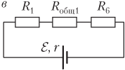
Full (closed) chain is depicted in fig. 8.9.
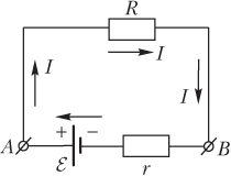
Fig. 8.9.
Points A and B are indicated by the EMF source terminals. The closed circuit can be divided into two sections:
- internal - a plot containing the source of EDC;
- external - a plot that does not contain the source of the EDC.
Electric current direction:
Parallel connection Connecting devices so that they are all subjected to the same voltage. Connecting the device so that they are all controlled by the same current. Distribution line Electrical line included in switchgear. Usually uses the average voltage, and the transformer is passed before connecting network networks, which is converted to a low-voltage standard of place in Brazil.
Transmission line Electrical line for transmission electrical Energy. This is a means of transmitting the energy generated in plants by several regions. Usually uses high voltage and connects to transformer substations. Maneuver technical term that determines the change in the electrical circuit configuration, made manually or automatically using a suitable device and intended for this purpose.
- in the inner chain - from "minus" to "plus";
- in the external chain - from the "plus" to "minus".
The strength of the current in a complete (closed) chain (see Fig. 8.9) is determined by the Ohm's law (the current in the closed chain containing the current source is directly proportional to the electromotive strength of this source and is inversely proportional to the sum of external and internal resistances):
Maneuver. The effect of changes in the electrical circuit by turning on and off the circuit or even redirects different parts of this scheme. Corrective maintenance service is performed after failure. Designed to replace the subject under the conditions of execution of its function. It is important to emphasize that preventive service is the most recommended. In the absence of an ideal procedure, corrective maintenance is the work that those who are responsible for state bodies are usually carried out; companies; clubs; condominiums and residences.
I \u003d ℰ R + R,
where I is the current strength; ℰ - the electromotive force (EMF) of the source, ℰ \u003d a st / q; A ST - the work of third-party strength (forces of non-flaunt origin) to move the positive charge Q; R is an external chain resistance (load); R is the internal resistance of the current source.
In the case of burning light bulbs and reactors, the level of illumination or illumination is reduced over time, which is minimally necessary, which affects the sharpness of the people. Preventive maintenance Maintenance is performed at specified intervals or in accordance with prescribed criteria designed to reduce the likelihood of refusal or deteriorating equipment. When illuminated, preventive maintenance provides regular lamp substitutions depending on their service life, even before burning.
This procedure is recommended, since the lamps will depreciate their light flux over time. When the consumption is below 75% of the nominal value of the project, this is the optimal exchange point. From this point on, the illumination decreases, which damages the visual severity of people.
Fig. 8.9.
The electromotive force (EMF) of the current source in a closed circuit is the amount
ℰ \u003d IR + IR,
where IR is a drop in voltage (potential difference) at the external section of the chain; IR - voltage drop in the source; I - current strength; R is an external chain resistance (load); R is the internal resistance of the current source.
The reduced equation recorded in the form
Power Meter Measuring Tool active energy By integrating the active power depending on the time in the KWTH consumption unit. Measurements are performed by equipment and are controlled by employees of the power distributor. It is necessary to know the average measurements that are damaged to consumers, since they do not allow to evaluate the energy savings achieved. The average charge has a 90-day period or 03 of electricity bills.
Power meter Power meter, which also indicates the highest value of the need for a specified time interval. This device is used on facilities with the contractual demand of class A, such as: industries; Shopping centers; supermarkets; Great Condo; Similar stadiums and buildings.
ℰ - IR \u003d IR,
specifies to equality potential differences on current source terminals U r \u003d ℰ - IR and potential differences on the external section of the chain U R \u003d IR, i.e.
U r \u003d u r.
Short circuit In the total chain, if the load in the outer chain is absent, i.e. The external resistance is zero: r \u003d 0.
Power factor meter The tool intended for measuring the ratio of the active power to the apparent power of the electrical circuit. Multimeter multifunctional and multifunctional device designed to measure voltage, current, and sometimes others electrical quantities, such as resistance, for example.
The neutral conductor of a single-phase, two-phase or three-phase system is constantly connected without current. The general term refers to both a neutral point and to a neutral conductor. Some objects are not neutral. For example: interphasis connections that do not have neutral.
Tok Power short circuit I is determined by formula
Example 8. EMF of the current source is 18 V. The resistor is connected to the source, the resistance of which is 2 times the internal resistance of the source. Determine the potential difference at the current source clips.
Decision . The potential difference at the source clips is determined by the formula
Insulation level Set of nominal supported stresses assigned to equipment or various elements electrical system. Determines the laboratory test voltage, which must withstand the insulation of the electrical device under certain conditions. The entire electrical installation material, even described by insulation, can carry out electricity from the specified voltage value, which is destroyed by the insulating property, thereby destroying the insulating element. There is a fire, destroying insulating with overvoltage.
U \u003d ℰ - IR,
where ℰ is the EMF of the current source; I - the power of the current in the chain; R is the internal resistance of the current source.
The strength of the current is determined by the Ohm's law for the total chain:
I \u003d ℰ R + R,
We substitute this expression in the formula for calculating the potential difference at the source clips:
U \u003d ℰ - ℰ R + R \u003d ℰ (1 - R R + R) \u003d ℰ R + R.
Taking into account the relationship between resistance resistor and source (R \u003d 2R) we obtain
Profiled small tray or tray. The product is used to create suspended systems in relatively high places of the right leg, to install the lamps, for placing the reactors and to lay the wiring. Electric polarity The relative situation of two-point potentials that are in opposition to positive and negative charges. In the frequency of oscillations in Hertz 60 polarity variations in one second, Brazilian standard.
If you refer to electricity, do not use the term "power", which is incorrect. Visible power is a vector amount between the active power and reactive power. Active power The term used to indicate the power when it is necessary to distinguish the apparent force, visible power, complex power and its components, as well as active and reactive power.
U \u003d 2 ℰ 3.
The calculation gives the value:
U \u003d 2 ⋅ 18 3 \u003d 12 V.
The potential difference at the source clips is 12 V.
Example 9. The internal resistance of the battery is 1.5 ohms. When the resistor is closed on the resistor, the resistance of 6.0 ohms battery of elements gives a current by force 1.0 A. Find strength of a short circuit current.
Decision . The short circuit current is determined by the formula
Power rating The sum of the rated power of the entire existing or planned equipment used in the installation, or the segment of the installation segment capable of working simultaneously. The value of this amount is a guideline for designing protection schemes.
Input power Total power consumed by an electrical device or a set of devices. Output power Power is transmitted by an electrical device in a particular form and assignment. Also called "useful power". The installed capacity is the sum of the rated power of the same type of electrical equipment in the installation, which is ready to work after completing work.
where ℰ is the EMF of the current source; R is the internal resistance of the current source.
According to the law of Ohm for the full chain,
I \u003d ℰ R + R,
where R is the resistance of the resistor.
Express from the recorded formula of the Source EMF and substitute for a short circuit current expression:
i \u003d i (R + R) R.
Calculate:
i \u003d 1.0 ⋅ (6.0 + 1.5) 1.5 \u003d 5.0 A.
The potentiometer is a resistive element that slides contact which allows you to continuously adjust the output resistance between almost zero and the maximum value of the resistive element. No energy savings, if we use the potentiometer pure and simply as a dimmer.
Accuracy The accuracy of the digital tester is defined as the difference between the indication and the actual value of the value measured under the starting conditions. The accuracy is specified in the format: The first value determines the error's percentage relative to the reading, which means that it is proportional to the input.
The short circuit current for the source with the specified values \u200b\u200bof the EMF and internal resistance is 5.0 A.
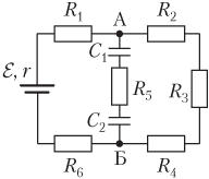
Example 10. Six identical resistors of 20 ohms each are connected to the circuit as shown in the figure. To the ends of the site are connected to a source with an emf equal to 230 V, and an internal resistance of 2.5 ohms. Find an Ampmeter AM readings.
The spread of light numerous experiments show that the light applies in direct and in all directions, in any homogeneous and transparent environment. The beam of light is called a line indicating the direction of the spread of light. A plurality of rays starting from the point is a beam. If the point from which the rays comes far away, the rays are considered parallel. In a darkened house, a small hole in the window allows you to observe a direct trajectory of light. In the same way, if we make a few holes in the walls of an opaque box and light the lamp inside it, we will understand that the light comes out through all the holes, that is, it applies in all directions.
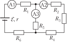
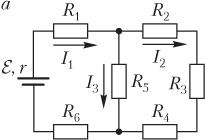
Decision . In fig. And the circuit is shown on which the currents flowing into its separate areas are indicated.
In the resistance area R 1 flows current I 1. Next, the current i 1 branches into two parts:
Operation performed by ignitions and starters leads to the launch of the ignition of some gas-discharge lamps and fluorescent lamps. It is based on the calculation of the energy account. Box where are located automatic switches or fuses from which chains are closed that provide accommodation.
Quality This widespread expression is not entirely understandable to the consumer as a whole. The product that is designed with this prerequisite will comply with security standards, methods of its specific use and current legislation. It will contain the accumulation of technologies that the manufacturer was able to combine over the years of research, experiments and proposals from customers and resellers. Therefore, the old saying "cheap comes is expensive" is very relevant. When buying electrical equipment, the lowest cost associated with this will be included in the acquisition, which is much higher than the cost of electricity, which the usual user does not see.
- on a plot with series connected resistors R 2, R 3 and R 4 flows current I 2;
- on the resistance area R 5 flows current I 3.
In this way,
I 1 \u003d i 2 + i 3.
These areas are interconnected in parallel, so the voltage drops on them are the same:
I 2 Rs 2 \u003d i 3 R 5,
where R is common - the resistance of the section with successively connected resistors R 2, R 3 and R 4, R Ohch2 \u003d R 2 + R 3 + R 4 \u003d 3R, R 2 \u003d R 3 \u003d R 4 \u003d R, R 5 \u003d R.
We also have the cost of maintenance and replacement of the product. Voltage drop difference between voltages existing in two points along the chain in which there is a current. Or the difference between voltages in two points along electrical line At the moment. Frequent voltage drops threaten all electrical equipment that does not have self-regulating, reduces its service life or causes premature burns and non-working electrical devices.
The voltage drop in the voltage loss in the circuit during current transportation. Expansion of communication A set of conductors and accessories installed between the point of departure of the power supply network and the delivery point. Two-phase electric network distribution networkconsisting of two phases and one neutral.
Recorded equations form the system:
I 1 \u003d i 2 + i 3, i 2 R total 2 \u003d i 3 R 5. )
Taking into account the expressions for R Ohch2 and R 5, the system takes the form:
I 1 \u003d i 2 + i 3, 3 i 2 \u003d i 3. )
Solution of the system relative to the current strength i 2 gives
I 2 \u003d i 1 4 \u003d 0.25 i 1.
This expression determines the desired value - the current strength in the AM ammeter A2.
The strength of the current i 1 is determined by the law of Ohm for the full chain:
Secondary distribution network Three-phase distribution network of power grid companies. It is usually used to feed public and private roads and buildings, usually providing voltage 220 V between phases, both air and underground. Single-phase network Electrical distribution network consisting of one phase and one neutral.
Three-phase electrical distribution network, consisting of three phases and one neutral. Electric photorele. The public and external lighting device, which works when switching contacts caused by the activation of the photocell. This device contributes to saving energy through the automation of the operation of the light points at a specified level.
I 1 \u003d ℰ R common + R,
where R total is the overall resistance of the external chain (resistors R 1, R 2, R 3, R 4, R 5 and R 6).
Calculate the overall resistance of the external chain.
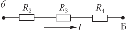
To do this, we transform the scheme as shown in Fig. b.
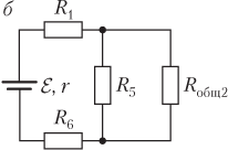
Sections R Ohch2 and R 5 are connected in parallel, their overall resistance
R total 1 \u003d R total 2 R 4 R total 2 + R 4 \u003d 3 R 4 \u003d 0.75 R,
where R is 2 \u003d 3R; R 4 \u003d R.
Once again we transform the scheme as shown in Fig. in .
Plots of resistances R 1, R total1 and R 6 are connected consistently, their overall resistance
R total \u003d R 1 + R total 1 + R 6 \u003d R + 0.75 R + R \u003d 2.75 R,
where R is 4 \u003d 0.75r and R 1 \u003d R 6 \u003d R.
The desired current is determined by the formula
I 2 \u003d 0.25 i 1 \u003d 0.25 ℰ 2.75 R + R.
Calculate:
I 2 \u003d 0.25 ⋅ 230 2.75 ⋅ 20 + 2.5 \u003d 1.0 A.
AMPERMETER A2 will show current strength 1.0 A.
Example 11. Six identical resistors for 20 ohms each and two capacitors with electrical circuits 15 and 25 μF are connected to the circuit as shown in the figure. To the ends of the site are connected to a source with EDC, equal to 0.23 kV, and an internal resistance of 3.5 ohms. Find the potential difference between the edges of the second capacitor.
Decision . Between points A and B does not flow, as capacitors are included between these points in the circuit. To determine the difference in potentials between the specified points simplifies the scheme, excluding the part of the AB.
In fig. And the scheme of a simplified chain is shown.

The current flows through the resistors R 1, R 2, R 3, R 4 and R 6, connected in series. General resistance of such a chain:
R general \u003d R 1 + R 2 + R 3 + R 4 + R 6 \u003d 5R,
where R 1 \u003d R 2 \u003d R 3 \u003d R 4 \u003d R 6 \u003d R.
The strength of the current I is determined by the Ohm's law for the total chain:
I \u003d ℰ R common + r \u003d ℰ 5 R + R,
where ℰ is the EDC of the current source, ℰ \u003d 0.23 kV; R is the internal resistance of the current source, R \u003d 3.5 ohms; R total - the overall chain resistance, R common \u003d 5r.
Calculate the drop in voltage between points A and B.
Between points A and B are resistors resistances R 2, R 3 and R 4, interconnected in each other, as shown in Fig. b.
Their overall resistance
R Ohch1 \u003d R 2 + R 3 + R 4 \u003d 3R.
The voltage drop on these resistors is determined by the formula
U ab \u003d IR general1,
or explicitly -
U ab \u003d 3 ℰ R 5 R + R.
Between points A and B included the capacitor battery C 1 and C 2, interconnected between each other, as shown in Fig. in .
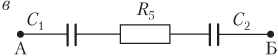
Their total electrical capacity
C total \u003d C 1 C 2 C 1 + C 2,
where C 1 is the electrical capacity of the first capacitor, C 1 \u003d 15 μF; C 2 - electrical capacity of the second capacitor, C 2 \u003d 25 μF.
Potential differences on battery plates:
U common \u003d Q c total,
where Q is the charge on the plates of each of the capacitors (coincides with the charge of the battery with a consecutive connection of the capacitors), q \u003d \u003d C 1 U 1 \u003d C 2 U 2; U 1 - the potential difference between the edges of the first capacitor; U 2 is the potential difference between the plates of the second capacitor (the desired value).
In an explicit form, the potential difference between capacitor clamps is determined by the formula
U SURE \u003d C 2 U 2 C total \u003d (C 1 + C 2) U 2 C 1.
The voltage drop on the resistors between points A and B coincides with the potential difference on the capacitors battery connected to the specified points:
U ab \u003d u common.
This equality recorded explicitly
3 ℰ R 5 R + R \u003d (C 1 + C 2) U 2 C 1,
allows you to obtain an expression for the desired value:
U 2 \u003d 3 ℰ R C 1 (5 R + R) (C 1 + C 2).
Calculate:
U 2 \u003d 3 ⋅ 0.23 ⋅ 10 3 ⋅ 20 ⋅ 15 ⋅ 10 - 6 (5 ⋅ 20 + 3.5) (15 + 25) ⋅ 10 - 6 \u003d 50 V.
Between the plates of the second capacitor, the potential difference is 50 V.
Full-text search:
Home\u003e Abstract\u003e Industry, production
Ohm law for an inhomogeneous section of the chain.
To occur in the electrical current conductor, it is necessary that the electrical field existed inside the conductor, the sign of which is the presence of potential difference at the ends of the conductor.
Create an electric field in an electrical circuit can be at the expense of the charges available in it. To do this, it is enough to divide the charges of opposite signs, concentrating in one area of \u200b\u200bthe chain is excess positive charge, in the other - negative (to create noticeable fields, it is enough to divide the negligible part of the charges).
The separation of multi-dimensional charges cannot be carried out by the power of electrostatic (Coulomb) interaction, since these forces not only do not disconnect, but on the contrary, they seek to connect the charges of opposing signs, which inevitably leads to equalization of potentials and the disappearance of the field in conductors. The separation of multimenamic charges in the electrical circuit can be carried out only by non-electrical origin.
Forces separating charges in the electrical circuit, creating an electrostatic field in it, are called third-party.
Devices in which third-party power are called sources of current.
The nature of third-party strength may be different. In some sources, these forces are due to chemical processes (galvanic elements), in other - diffusion of charge carriers and contact phenomena (contact EDC), in the third - the presence of a vortex electric field (electrical generators), etc. Third-party forces act on charges only in current sources, and there they act either all the ways of following charges through the source or in some sections. In this regard, they talk about sources with distributed and focused third-party forces. An example of a source with distributed third-party forces can be an electrical generator - in it these forces act on the entire length of the anchor winding; An example of a source with focused third-party forces can be a galvanic element - in it these forces act only in the finest layer adjacent to the electrodes.
Since third-party valid only in the source, but electrostatic - and in the source and in the external chain, then there are areas in any chain, where third-party and electrostatic forces are also operating on charges. A plot of chain in which only electrostatic forces act on charges is called, as already mentioned, uniform. The plot in which electrostatic, and third-party power are also operating on charges inhomogeneous. In other words, a non-uniform area is a plot containing the current source.
When moving charges for such a plot, electrostatic and third-party forces make work. Third-party work characterizes electromotive force (Abbreviated EDC).
Electromotive force on this section of the chain 1-2 is called scalar physical quantity, numerically equal to work performed by third-party forces when moving a single, positive point charge From point 1 to point 2
The work of electrostatic forces characterizes potential difference.
The potential difference between points 1 and 2 of the electrical circuit is called a scalar physical quantity, numerically equal to the operation performed by electrostatic forces when moving a single, positive point charge from point 1 to point 2
 .
.
The joint work of third-party and electrostatic forces on this section of the chain characterizes the voltage.
The voltage in this section 1-2 is the physical quantity, numerically equal to the algebraic amount of work performed by electrostatic and third-party forces when moving a single, positive point charge from the point1 exactly2 .
 .
.
Or, in other words, ![]() .
.
If the resistance of the inhomogeneous site 1-2 Equally, the current flows I. , Taking advantage of the law of conservation of energy, it is possible to obtain the law of Oma for the inhomogeneous section of the chain.
If the current in the chain is stationary, the plot of the chain is still not changed and its temperature does not change, the only result of the current operation on this site will be the highlight of heat to the environment. Complete operation of current, folding from the works of electrostatic and third-party forces, during t. equal to the number of heat excreted.
and ![]() .
.
Then, and after cuts
![]() .
.
From here  - Ohm law for an inhomogeneous section of the chain in the integral form: the strength of the current in the inhomogeneous section of the electrical value is directly proportional to the algebraic amount of the potential difference at the ends of the section and the EMF, acting in this section, and inversely proportional to the full resistance of the site.
The strength of the current, the difference of potentials and the EMF in this formula is the magnitude of algebraic. Their sign depends on the direction of parting the site. If the direction of the current coincides with the direction of bypass, it is considered positive. If the current source sends a current in the direction of bypass, its EMF is considered positive. The following is an example of the entry of the Ohm law for an inhomogeneous section of the chain shown in Fig. 52.

![]()
When bypass from a to  ,
,
from in to a  .
.
That is, when changing the direction of bypass, all the values \u200b\u200bincluded in the Ohm law change the sign.
Thus, the law of Oma and for homogeneous and for inhomogeneous sites is one of the manifestations of the law of conservation and turning the energy.
4.5. The consequences of the Ohm law for the inhomogeneous section of the chain.
Consider the consequences arising from the Ohm law for the inhomogeneous section of the chain.
1. If there is no current source in this section (
12
=0
), then we get the law of Oma for a homogeneous site  ,
,
from where it follows that ![]() or
or ![]() .
.
The voltage and the difference of potentials on a homogeneous section of the chain are equal to each other.
 2. If you consider a closed chain, then or. Substituting it in the original formula, we get
where
![]() - full chain resistance- resistance to the outer section of the chain, - resistance of the inner portion of the chain (current source).
- full chain resistance- resistance to the outer section of the chain, - resistance of the inner portion of the chain (current source).
![]() Then.
Then.
The strength of the current in a closed circuit is directly proportional to the EMF and inversely proportional to the full chain resistance- Ohm's law for the full chain.
3. If the circuit is open, there is no current in it ( I.=0 ) IR=0 .
Then ![]() , i.e EMF is equal in absolute value and is opposite to the sign of the potential difference at the clips of the open source.
, i.e EMF is equal in absolute value and is opposite to the sign of the potential difference at the clips of the open source.
4.6. Power in chains direct current.
The power of the electric current on a homogeneous area of \u200b\u200bthe chain with resistance is sufficiently simple can be found as the ratio of the work performed by the electrostatic field to move in charges of charges by the time for which this work is performed:
In this way, the power of the electric current on the circuit section is proportional to the square of the current strength and the resistance of the site.
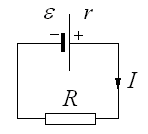
If you consider a closed chain (Fig. 53), then in such a chain it is customary to consider two types of power - complete and useful. Full Called the power that stands out throughout the circuit, that is, both on the external resistance and on the internal resistance of the current source. Then complete power can be found as a product of the current of the current for the total chain resistance:
![]() , and using the Ohm law for a closed chain, we get:
, and using the Ohm law for a closed chain, we get:
 .
.
Useful call the power that stands out on the external resistance of the chain, that is, it is equal ![]() And again applies the Ohm law for a closed chain, we get:
And again applies the Ohm law for a closed chain, we get:  .
.
Efficient efficiency (efficiency) a closed chain call the ratio of useful power to full. Using the derived formulas, we get:
![]()
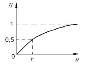
We find out how useful, full power and efficiency depend on the resistance of the external chain. It can be seen that the complete power is maximal when and decreases with increasing external resistance. Useful power at first increases from zero to some value, and then decreases with growth. To find out with what value the useful power is maximal, it is necessary to equate to zero derivative.
 from here after cutting we get
Thus, the maximum power in the outer chain develops, provided that the resistance of the outer chain is equal to the internal resistance of the current source. We note that with this condition, the efficiency is only 0.5, that is, only half of the power developed by the source of the current is released in the outer chain, the remaining power goes to heating the source itself. 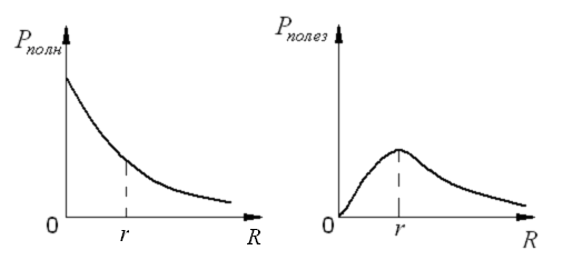
![]()
In fig. 54 graphically depicts the dependences of complete and useful power, as well as the efficiency for a closed chain from the external resistance of the chain.
Bibliographic list
Savelyev I.V. Course of general physics: T.2. Electricity. - M.: Science, 1987. - 432 p.
Trofimova T.I. Course of physics: studies. Handbook for universities. - 7th ed., Ched. - M.: Higher. School, 2003. - 542 C.: IL.
Detlaf F.F., Yavorsky B.M. Course of physics: studies. Handbook for themp. - M.: Science, 1989. - 608 p.
Preface .......................................................................................... 3
1. Electric field in vacuum .................................................................. 4
1.1. Electromagnetic field - material carrier
electromagnetic interaction .................................................... 4
1.2. Electric charges ............................................................... .......
1.3. Cut law ............................................................... ..................... 5
1.5. Principle of superposition of fields ............................................................. 7
1.6. Calculation of electric fields based on the principle of superposition ............... 8
1.7. Lines of tension vector ...................................................... ..10
1.8. Stream vector of tension ...................................................... ... 11
1.9. Gaussian theorem ................................................................................ 13
1.10. The use of the Gauss Theorem to the calculation of electric fields .................12
1.11. Work of the power of the electrostatic field .............................. ..................... 18
1.12. Circulation of the tension of the electrostatic field ......... ...... 19
1.13. The potential of the electrostatic field ................................. ................. 20
1.14. Communication between the tension and the potential of the electrostatic field..21
1.15. Calculation of the potential and potential difference in the electrostatic field ... 23
2. Electric field in dielectrics ................................................................. ... 24
2.1. Conductors, dielectrics, semiconductors .................................... ... 24
2.2. Polarization of dielectrics ............................................................ 25
2.3. Polarization types .......................................................................26
2.4. The relationship of the values \u200b\u200bcharacterizing polarization ............ ................. 28
2.5. Electric field in dielectrics .................................... ................. 29
2.6. Vector of electrical displacement ....................................... ................. 30
2.7. Calculation of the electric field in the presence of dielectrics ........................ 33
2.8. Segnetoelectrics ........................................................................ 33.
2.9. Piezoelectric effect. Electrotrix ................................. ... 35
3. Conductors in the electric field. Electric field energy ................36
3.1. Distribution of charges on the conductor ................................. .................. 36
3.2. Explorer in an external electric field .................................... ... 38
3.3. Conductor electrical capacity ......................................................... 39
3.4. Mutual electrical capacity. Condenters .......................................... 40.
3.5. Constressor connection ............................................................ 41
3.6. Energy of the system of fixed point charges .................. ................. 42
3.7. Own energy charged conductor and condenser ............... 43
3.8. Energy electric field ......................................................................... 44
4. DC laws .................................................................. .45
4.1. The concept of electric current ...................................................... 45
4.2. Ohm's law for a homogeneous section of the chain ....................................... ... 47
Always closed, ... Lecture \u003e\u003e Natural science
No missing. Present course Deals with modern concepts ... The magnetostatic field is generated permanent tokami, the existence of which ... Unlike elektostatiki, consistent the theory of magnetic ... conducting review lectures- Discussions after ...
Methods of application of the COR in the process of studying the topic Electromagnetic oscillations
Coursework \u003e\u003e PedagogyThermodynamics I. molecular physics, electrostatics, optics, atomic and nuclear ... Number of experimental materials. Course "Open Physics 2.0" ... the law established for permanent tok., to describe processes ... Developed in the form lecturessince this ...


