When considering the interaction of charged bodies and point charges, the question arises, why are the forces acting on charges, sometimes at a very long distance and separated by emptiness (vacuum)? To answer this question, the presence between charges of a physical agent that transfers this interaction should be assumed. In the 1830s, M. Faraday developed the theory of the closest, from which the concept flowed down electromagnetic field.
According to this theory, any charge is a source of an electromagnetic field propagating in space with a speed of light. In the case of fixed charges, this field is called electrostatic. Its main property is that the force placed in this field is in force. Thus, we can assume that non-charges interact directly with each other, and each of the fixed charges creates an electrostatic field in space, which acts on another charge. The electrostatic field is described by two values: potential and tension.
Tension electric field is the power vector characteristic of the electric field and is equal to the power acting on triala positive charge, placed at this point of the field divided by the amount of this charge (the trial charge should have a sufficiently small size in order not to distort the measured field):
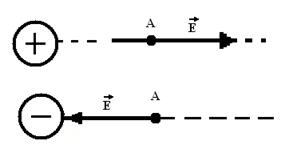
The direction of the vector coincides with the direction of force acting on a positive charge.
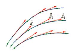
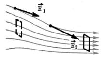
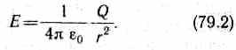
Graphically electrostatic field are depicted using lines of tension (silest lines) - lines tangents to which at each point coincide with the direction of the vector (Fig. 1.3). For the power lines, the direction is selected, which coincides with the direction of the tension vector, while such lines never intersect. When uniform field (When the tension vector at any point of space is constant module and direction) intensity line parallel to the tension vector.
In order to graphically characterize not only the direction, but also the tension module electrostatic field, power lines are carried out with a certain little: The number of lines of the tension of the surface of the surface area, perpendicular to the intensity lines, should be equal to the modulus of the tension vector: (Fig. 1.3).
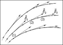
Fig. 1.3. Power lines Electric inhomogeneous field
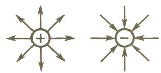
The power lines of the Coulomb fields of positive and negative point charges are shown in Fig. 1.4.
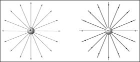
Fig. 1.4. Power lines of point charges
For the electrostatic field fair superposition principle: The tension of the charge system field is equal to the vector sum of field strengths that would create each of the charge charges separately:
where - the electric field strength created by the charge at this point. The principle of superposition allows you to calculate the intensity of the field of any system of fixed charges, submitting it in the form of a set of point charges.
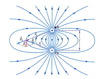
As an example applying the principle of superposition of fields in Fig. 1.5 depicts the pattern of power lines of the electric field dipole - systems of two identical charges of different signs q. and - q.located at some distance l..
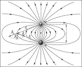
Fig. 1.5. Power lines of the electric dipole field
Electrical displacement. Gauss Theorem for the Electrostatic Field in Dielectric
The tension of the electrostatic field depends on the properties of the medium: in a homogeneous isotropic medium field strength E. Inversely proportional to E. . The vector of tension E, moving across the dielectric boundary, undergoes a jump-like change, thereby creating inconvenience when calculating electrostatic fields. Therefore, it turned out to be necessary in addition to the tension vector characterize the field yet electrical displacement vector which is equal to an electrically isotropic medium
D \u003d EE 0 E. (1)
Using formulas e \u003d 1 + C and P \u003d CE 0 E, vector electric displacement can be expressed as
D \u003d E 0 E + P (2)
The unit of electrical displacement is a pendant per meter in a square (CL / m 2).
Related charges appear in a dielectric in the presence of an external electrostatic field created by the system of free electrical charges, i.e., an additional field of associated charges is superimposed in a dielectric to the electrostatic field of free charges. Resulting field B. dielectric is described by a vector intensity E, And therefore it depends on the properties of the dielectric. Vector D. Describes the electrostatic field created by free charges. Related charges arising in dielectric can cause redistribution of free charges that create a field. Therefore, vector D. characterizes the electrostatic field created free charges(i.e. in vacuum), but with such a distribution in space, which is with a dielectric.
Similarly, like the field E, field D. Depicted with help electrical displacement lines The direction and density of which are determined in the same way as for lines of tension.
E. vector lines can start and end on any charges - free and related, while vector lines D - only on free charges. Through field areas where are related charges, line vector D. pass without interrupting.
For arbitrary closed Surface S Vector Stream D. Through this surface
Gaussian theorem for the electrostatic field in the dielectric:
 (4)
(4)
i.e. the flow of the vector of the electrostatic field in the dielectric through an arbitrary closed surface is equal to the algebraic amount of prisoners within this surface free Electrical charges. In this form, the Gauss Theorem is valid for the electrostatic field for both homogeneous and isotropic and non-uniform and anisotropic media.
We will withdraw the differential form of the Gaussian theorem for the electrostatic field in the dielectric. Applicable (4) to the small surface DS, which limits the small volume DV and containing DQ charge. We divide both parts on DV and move to the limit when DV's desire to zero:
 (5)
(5)
The limit standing in the left side of the expression (5) determines the value called field divergence. Then the expression (5) can be recorded
dIV D \u003d S,(6)
where S is the bulk density of the free charge.
The practical aspect of the Gauss Theorem is that with its help, symmetric electrical fields are calculated in inhomogeneous media.
Electrical capacity solitary
Explorer
Consider secluded conductor i.e. conductor who is removed from other conductors, bodies and charges. Its potential is directly proportional to the charge of the conductor. Different conductors, being the same charged, take various potentials, so you can record a secluded conductor
Proportionality coefficient FROMcalled electrical capacity of the conductor.From (1) it follows that
The capacity of the secluded conductor is determined by the charge, the message of which the conductor changes its potential per unit. The conductor capacity depends on its size and shape, but does not depend on the material, aggregate state, Forms and sizes of cavities inside the conductor. This is due to the fact that excess charges are distributed on the external surface of the conductor. The capacity is also not dependent on the charge of the conductor or on its potential.
Electricity unit - farad(F): 1 F. -The capacity of such a secluded conductor whose potential changes to 1 V when the charge in 1 cells is reported.
Capacity of the secluded radius ball R, in a homogeneous medium with dielectric constant E, equal
![]() (3)
(3)
From (3) it follows that the capacity in 1 F. Would have a secluded ball in vacuo and having a radius R \u003d 9 × 10 6 kmwhat about in 1400 Once than the radius of the Earth (the electrical capacity of the earth C \u003d 0,7mf). Since Farad is a very large value, then practices use dolly units - Millinarad (MF), microfrades (IFF), Nanofarad (NF), Picophadrad (PF). From formula (3 it follows that unit of electrical constant E 0 pharad per meter (F / M).
Condencators
Condenserscalled devices with ability at small sizes and small relatively surrounding potentials to accumulate significant charges, i.e., possess a large capacity.
If you bring other bodies to the charged conductor, then they occur induced (on the conductor) or related (on dielectric) charges, and the closest charge close to the leading charge Q. There will be charges of the opposite sign. These charges weaken the field created by the charge Q, i.e. reduce the potential of the conductor, which leads to an increase in its electrical capacity.
The capacitor consists of two conductors (plates) separated by a dielectric. The capacitance of the capacitor is short, to have the effects of the surrounding bodies, so the conductors give such a form so that the field created by the accurate charges is focused in a narrow gap between the condenser plates. This condition is satisfying: two flat plates; two coaxial cylinders; Two concentric spheres. Therefore, depending on the form of plates, the capacitors are divided into flat, cylindrical and spherical.
Since the field is concentrated inside the capacitor, the tension lines begin on one lamp and end on another, therefore free charges arising from different plates are equal to the module with multi-dimensional charges. Capacity condenser called physical quantityequal to the ratio of charge accumulated in the condenser, to the potential difference between its plates:
 (1)
(1)
If the distance between the capacitor plates is not enough compared to their linear dimensions, then the edge effects can be neglected and the field between the plates is considered homogeneous. If there is a dielectric between the plates, the potential difference between them is equal
 (2)
(2)
where ε - the dielectric constant.
Capacity of a flat condenser:
Cylindrical capacitor capacity:
 ,
,
where L is the length of the capacitor, R 1, R 2 are the radii of internal and external plates.
Capacity of a spherical condenser:
Condenters are characterized punch voltage- the potential difference between the capacitor plates at which occurs breakdown- Electric discharge through a dielectric layer in the condenser. The punching voltage depends on the form of the plates, the properties of the dielectric and its thickness.
To increase the tank and varying its possible values, capacitors are connected in the battery, while their parallel and serial connection is used.
I. Parallel condenser connection
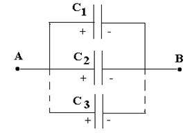
In parallel condensers, the potential difference on the plates of capacitors is the same and equal to J A -J V. If the capacity of individual capacitors C 1, C 2, ...., CN, then their charges are equal
![]()
![]()
………………………
![]() ,
,
and the charge of the battery capacitors
The total capacity of the battery is equal to the sum of the containers of individual capacitors
The allowable voltage is determined by the permissible voltage of the smaller capacitor.
2. Serial connection of capacitors.
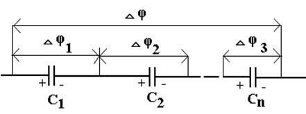
In sequentially connected capacitors, the charges of all the plates are equal to the module, and the potential difference on the clips of the battery

where for any of the capacitors under consideration
On the other hand,
i.e., with a sequential connection of capacitors, values, inverse containers are summed up. Thus, with a consecutive connection of capacitors, the resulting container FROMalways less smallest containers used by the battery.
Electric dipoles
Two equal charges of the opposite sign, + Q.and- Q,located at a distance of L from each other form electric dipole.Value QLcalled dipole Momentand denotes symbol r.Many molecules have a dipole moment, for example, the CO dive (atom C has a small positive charge, and about a small negative charge); Despite the fact that the molecule is generally neutral, there is a separation of charges due to the unequal distribution of electrons between the two atoms. (Symmetric diatomic molecules, such as 2, do not possess the dipole moment.)
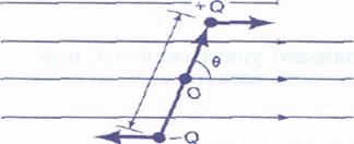
Consider the dipole at the beginning with the moment ρ \u003d QL,placed in homogeneous electric field tension ε. The dipole moment can be represented as a vector P equal to an absolute value. QLand directed from the negative charge to the positive. If the field is uniform, then the forces acting on a positive charge, QEand negative - QEdo not create the resulting force acting on the dipole. However they lead to the emergence torquewhose value is relative to the middle of the dipole ABOUTequal
or in the vector
As a result, the dipole seeks to turn so that the vector P was parallel to E. Work W,the electric field performed above the dipole, when the angle θ varies from q 1 to Q 2, is given by expression
As a result of the operation performed by the electric field, decreases potential energy U.dipole; If put U.\u003d 0, when p ^ ε (θ \u003d 90 0), then
U \u003d -w \u003d - pecosθ \u003d - p · ε.
If the electric field inhomogeneouslythat the forces acting on the positive and negative charges of the dipole may be unequal in size, and then the resulting force will continue to the dipole, except for the torque.
So, we see what happens with an electric dipole placed in an external electric field. Let us now turn to the other side of the case.
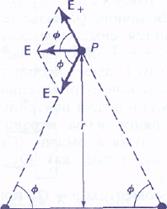
fig. Electrical field created by an electric dipole.
Suppose there is no external field, and determine the electric field created by the dipolem himself(capable of acting on other charges). For simplicity, limit ourselves to the points located on the perpendicular to the middle of the dipole, like a point Ρ in fig. ???, located at a distance of the middle of the dipole. (Note that RNA Fig. ??? is not the distance from each of the charges to R,which is equal (R 2 +/ 2/4) 1/2). Increased electric field in: point Ρ equal
Ε = Ε + + Ε - ,
where E + and E is the field strength created by respectively positive and negative chargesequal to each other by absolute value:
Their y components at point Ρ mutually destroyed, and by absolute magnitude, the tension of the electric field ε is equal
 ,
,
 [Along the perpendicular to the middle of the dipole].
Departed from the dipole (R »/) This expression is simplified:
 [Along the perpendicular to the middle of the dipole, with R \u003e\u003e L].
It can be seen that the tension of the electric field of the dipole decreases with a distance faster than for point charge (as 1 / R 3 instead of 1 / R 2). This should be expected: at large distances, two charges of opposing signs seem so close to each other, they neutralize each other. The dependence of the form 1 / R 3 is also valid for points that are not lying on the perpendicular to the middle of the dipole.
Voltage
If only the forces of the electrostatic field are operating in the circuit on the current carriers, then the carriers are moved, from points with high potential to points with less potential. This will lead to equalization of potentials at all points of the chain and to the disappearance of the electric current. Therefore, for existence direct current It is necessary that in the chain, along with plots, on which positive charges move towards the decrease in the potential, there must be sections on which transfer positive charges It occurs in the direction of increasing the potential, i.e. against the power of the electrostatic field. To make the movement of positive charges from a lower potential to more, and negative - from a larger to a smaller, the power of non-electrical nature is necessary. Therefore, it is necessary in the chain of a device capable of creating and maintaining the potential difference due to the work of non-electrostatic forces. Such devices are called sources of current.Forces neophostrostatic origin, acting on charges from the sources of current are called third-party.
The nature of third-party strength may be different. For example, in galvanic elements, they arise due to energy chemical reactions between electrodes and electrolytes; In the generator, due to the mechanical energy of rotation of the generator rotor, etc., the role of the current source in electrical chain, the same as the role of the pump, which is necessary for pumping the fluid by the vhytraulic system.
Under the action of the field of third-party forces, electric charges are moving within the current source against the power of the electrostatic field, due to which the potential difference is maintained at the ends of the chain and the circuit flows the constant electrical current.
Third-party forces make work on moving electrical charges. The physical value determined by the work performed by third-party forces when moving a positive unit charge is called electromotive power (e.D.S..) e.operating in the chain:
This work is made due to the energy spent in the current source, therefore the amount e.you can also call the electromotive power of the current source included in the chain. ED, as well as the potential, is expressed in Volta.
Side force F ST STTs acting on the charge Q 0 , can be expressed as
![]() ,
,
where is the tension of the field of third-party strength. The work of third-party charges for the movement of charge Q 0.on a closed section of the chain is equal
![]() . (2)
. (2)
Dividing this expression on Q 0 , we get an expression for ED, acting in the chain:
![]() ,
,
i.e. E.D.S., acting in a closed chain, can be defined as circulation of the intensity vector of third-party strength. ED, acting on the site 1 - 2, equal
 (3)
(3)
On the charge q 0, in addition to third-party forces, the forces of the electrostatic field F e \u003d Q 0 E are also valid. Thus, the resulting force acting in the chain to the charge Q 0 is equal to
The work performed by the resulting force above the charge Q 0 in section 1-2 is equal
Using expressions (3) and  ,
,
we can write down
 . (4)
. (4)
For a closed chain (J 1 \u003d J 2) the operation of the electrostatic forces is zero, so
![]() .
.
Voltage U. in section 1-2, the physical value determined by the work performed by the total field of electrostatic (Coulomb) and third-party forces when moving a positive unit charge on this section of the chain.
![]() .
.
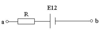
If E.D.S. contributes to the movement of positive charges in the selected direction (in the direction A-B), then E 12\u003e 0 (Fig. 1). If E.D.S. prevents the movement of positive charges in this direction, then E 12<0 (рис.2).
The plot of a chain, on which third-party power is not called, is called homogeneous. For a homogeneous section of the chain
![]()
The concept of voltage is a generalization of the concept of potential difference: the voltage at the ends of the circuit section is equal to the difference in potentials if there is no em., That is, there are no third-party forces.
A magnetic field
Fig. 2.
For the direction of the magnetic field, a direction that coincides with the direction of force may also be taken, which acts on the North Pole of the magnetic arrow placed at this point. Since both poles of the magnetic arrows lie in close points of the field, the forces acting on both poles are equal to each other. Consequently, a pair of forces turning it on the magnetic arrow so that the axis of the arrow connecting the south pole with the North coincided with the direction of the field.
A frame with a current can also be used for a quantitative description of a magnetic zero. Since the frame with the current is experiencing a field orienting effect, a pair of forces acts in a magnetic field. The torque depends on both the field properties at this point and the frame properties:
M \u003d [P M V], (1)
where In - vector magnetic induction,which is the quantitative characteristic of the magnetic poly, p M - vector magnetic moment framewith current. For flat circuit with current I
where S is the surface area of \u200b\u200bthe contour (frame), n is a single vector of normal to the surface of the frame. Direction p M. The coincides, thus, with the direction of positive normal.
If at this point of the magnetic field, placing a frame with different magnetic moments, then they act different torque moments, however, the ratio (M max is the maximum torque) for all circuits the same and therefore can be the characteristic of a magnetic poly, called magnetic induction:
Magnetic inductionat this point uniformthe magnetic field is determined by the maximum torque acting on the frame with a magnetic moment equal to one, when normal to the frame is perpendicular to the field direction. It should be noted that vector IN It can also be derived from the AMPER law and from the expression for the power of Lorentz.
Since the magnetic field is silov, then it, by analogy with electric, is depicted using magnetic induction lines. Magnetic induction lines - lines tangents to which at each point coincide with the direction of the vector IN. Their direction is set rule of right screw : the screw head screwed in the direction of current rotates in the direction of magnetic induction lines.
Magnetic induction lines can be "showing" with iron sawdust, magnetizing in the field under study and leading itself like small magnetic shooters.
 |
| Fig. 3. |
Magnetic induction lines always closedand covers conductors with current. They differ from the tension lines of the electrostatic field that are open(Begin on positive charges and end on negative).
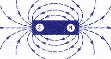
In fig. 3 shows the magnetic induction lines of the bandage magnet; They come out of the North Pole and go and South. Initially, it seemed that there was a complete analogy with the lines of electrostatic field strength, and the poles of magnets play the role, magnetic "charges" (magnetic monopoles). Experiments have shown that, cutting a magnet into parts, its poles cannot be divided, i.e., unlike electrical charges, free magnetic "charges" do not exist, therefore, the magnetic induction lines cannot break into the poles. In the future, it was found that inside the strip magnets there is a magnetic field, a similar field inside the solenoid, and the magnetic induction lines of this magnetic field are a continuation of magnetic induction lines outside the magnet. Thus, the magnetic induction lines of the magnetic field of permanent magnets are also closed.
So far, we have considered macroscopic currents current in conductors. However, according to the assumption of French physics A. Ampere (1775-1836), in any body there are microscopic currents caused by the movement of electrons in atoms and molecules. These microscopic molecular currents create their magnetic field and can be rotated in magnetic fields of macrovers. For example, if you have a current conductor with a current (macrotok) near some body, then under the action of its magnetic field, microcles in all atoms are definitely oriented, creating an additional magnetic field in the body. Vector magnetic induction in characterizes resultmagnetic field created by all macro-and microclesi.e. at the same current and other equal conditions IN in valid environments will have different values.
A magnetic field makrotokov described by N. intensity vector For a homogeneous isotropic medium, the magnetic induction vector is associated with a vector of tension by the following ratio:
![]() (3)
(3)
where m 0 is magnetic constant, M - the dimensionless value is the magnetic permeability of the medium, showing how many times the magnetic field of Maktorokov H.increased at the expense of the field of microtoks of the medium. Comparing the vector characteristics of electrostatic ( E. and D.) and magnetic ( IN and N.) Fields, We indicate that the analogue of the electrostatic field vector E.is the magnetic induction vector INsince vectors E.and INdetermine the power actions of these fields and depend on the properties of the medium. Analogue of an electrical displacement vector D. Is the vector of tension N. magnetic field.
A magnetic field
Moving charge
Each conductor with a current creates a magnetic field in the surrounding space. The electric current is an ordered movement of electrical charges. Therefore, it can be said that any single moving in a vacuum or environment creates a magnetic field around itself. As a result of the generalization of experienced data, a law was established that determines the field in a point charge Q,freely moving nonrelativistic speed V. Under free trafficit is understood by his movement at a constant speed. This law is expressed by the formula
 (1)
(1)
where R is a radius-vector spent Q.to the observation point. According to expression (1), vector IN Directed perpendicular to the plane in which the vectors are located v. and r., namely: his direction coincides with the direction of the transit movement of the right screw when it rotates v. to r.. Magnetic induction module (1) is calculated by the formula
 (2)
(2)
where a is the angle between vectors v. and r..
Comparing  and (1), we see that a moving charge on its magnetic properties is equivalent to an element of the current:
Regularities (1) and (2) are valid only at low speeds (V<<с) движущихся зарядов, когда электрическое поле свободно движущегося заряда можно считать электростатическим, т. е. создаваемым неподвижным зарядом, находящимся в той точке, где в данный момент времени находится движущийся заряд.
Fig. one
If speed v. The charged particle is directed at an angle A tovector IN (Fig. 1), then its movement can be represented in the form of two movements: 1) uniform rectilinear movement along the field at a speed; 2) a uniform movement with a velocity rate in a plane perpendicular to the field. The radius of the circle is determined by the formula (1) . As a result of the addition of both movements, a movement on the helix occurs, the axis of which is parallel to the magnetic field (Fig. 1). Screw pitch
![]()
Substituting in the last expression (2), we get
 .
.
The direction in which the spiral is spinning depends on the particle charge sign.
ELECTROMAGNETIC INDUCTION
Faraday law
Summarizing the results of their numerous experiments, Faraday came to the quantitative law of electromagnetic induction. Whenever a change in magnetic induction flux cloured with a circuit circuit, an induction current occurs in the circuit; The occurrence of induction current indicates the presence in the circuit of the electromotive force, called electromotive power electromagnetic induction. The value of the induction current, and consequently, e. D.S. electromagnetic induction is determined only by the rate of change of magnetic flux, i.e.
e I ~ DF / DT
The magnetic flux sign depends on the choice of positive normal to the contour. The positive direction of normal is associated with the current rule of the right screw. Consequently, choosing a certain positive direction of normal, we define both the magnetic induction flow sign and the direction of current and e. d. s. in the circuit. Faraday Electromagnetic Induction Act: E.D.S. Induction in the circuit is equal to the rate of change of magnetic flux through the surface limited by the contour.
The minus sign shows that the increase in the flow ( > 0) causes er d. s. e I.< 0 ,those. The induction current field is directed towards the flow; Flow reduction ( < 0) causes e.D.S. e I. \u003e 0, i.e. The flow direction and the induced current field coincide.
The minus sign in formula (1) is a mathematical expression of the Lenza rule - the general rule for finding the direction of the induction current.
Lenza rule: The induction current in the circuit always has such a direction that the magnetic field created by them prevents the change in the magnetic flux that caused this induction current.
E.D.S. Electromagnetic induction is expressed in volts.
What is Nature E. d. s. electromagnetic induction? If the conductor moves in a constant magnetic field, the Lorentz force acting on charges inside the conductor moving along with the conductor will be directed opposite to the current, i.e. it will create an induction current of the opposite direction in the conductor (for the direction electric current The movement of positive charges is taken). Thus, the excitation of e. d. s. Induction When the contour movement in a constant magnetic field is explained by the action of the Lorentz force arising when the conductor moves.
According to the Faraday law, the emergence of E.D.S. Electromagnetic induction is also possible in the case of a fixed circuit located in a variable magnetic field. However, Lorentz's power on fixed charges does not work, so in this case it cannot be explained by the emergence of er. d. s. induction. Maxwell for explaining er D.S. Inductions in fixed conductors suggested that any variable magnetic field excites the electrical field in the surrounding space, which is the cause of the induction current in the conductor. Circulation of the vector of this field on any fixed contour L. The conductor is e. d. s. Electromagnetic induction:
Electrostatic field. Electrostatic field tension
If in the space surrounding the electric charge, make another charge, then the Coulomb force will act on it; So, in space surrounding electrical charges, exists force field. According to the ideas of modern physics, the field really exists and along with a substance is one of the forms of the existence of matter, through which certain interactions are carried out between macroscopic bodies or particles that are part of the substance. In this case, they say the electric field - the field by which electrical charges interact. We will consider electrical fields that are created by fixed electrical charges and are called electrostatic.
To detect and experienced the electrostatic field uses trial point positive charge - Such a charge that does not distort the field under study (does not cause the redistribution of charges that create the field). If in the field created by the charge q, put the test charge Q 0 , then it acts on the power F is different in different points of the field, which, according to the law of the coulon, is proportional to the test charge Q 0 . Therefore, the ratio F / Q 0 does not depend on Q 0 and characterizes the electrostatic field at the point where the trial charge is located. This value is called tension and is the power characteristic of the electrostatic field.
Electrostatic field tension At this point, this is a physical value determined by force acting on a trial single positive charge placed in this field:
As follows from formulas (1.2.1) and (1.1.1), the field strength created by a point charge Q in vacuum at a distance of R from it
In vector form, expression (1.2.2) has appearance
![]()
The direction of tension vector coincides with the direction of force acting on a positive charge. If the field is created by a positive charge, the tension vector is directed along the steady-vector from charge to the external space (repulsion of a test positive charge); If the field is created by a negative charge, the tension vector is directed to the charge (Fig. 1.2.1).
From formula (1.2.1) it follows that the unit of tension of the electrostatic field - newton on the pendant (N / CL): 1 N / CL - the tension of such a field that is on the point charge 1 CL acts with force in 1 N.; 1 N / CL \u003d 1 V / m, where in (volt) is the unit of the potential of the electrostatic field.
Graphically electrostatic field are depicted using lines of tension - Lines , tangents to which at each point coincide with the direction of the vector E. (Fig. 1.2.2).
Intensity lines are attributed to the direction coinciding with the direction of the tension vector. Takakak In each given point of space, the vector is intensely attained only one direction, then the line of tension will never intersect.
So that with the help of tension lines, it was possible to characterize not only the direction, but also the value of the electrostatic field strength, it was agreed to carry out them with a certain denominator (Fig. 1.2.3): the number of tension lines that permeate the unit of the surface area, perpendicular to the intensity lines, should be equal to the module Vector tension.
For uniform field (When the vector of tension at any point is permanent in size and direction) intensity line parallel to the tension vector. In places where the field strength is less, tension lines are less common. If the field is created by a point charge, then the intensity line is radial straight, emerging from charge, if it is positive, and included in it if the charge is negative (Fig. 1.2.4).
The number of tension lines at any distance from the charge will be the same, that is, the tension lines nowhere except charges begin and do not end.
In fig. 1.2.5 shows the picture of the power lines of the field of an electric dipole - systems from two identical modulot of charges of different signs Q and -Q , located at some distance l.
Due to great clarity, the graphic method of representing the electrostatic field is widely used in electrical engineering.
Law of interaction fixed pointelectrical charges were installed in 1785 by Sh. Pendum using a twist weight, similar to those (see §22) were used by G. Cavendysh to determine the gravitational constant (earlier this law was opened by the city of Cavendis, but his work remained unknown more than 100 years). Pointcalled the charge focused on the body, the linear dimensions of which are negligible compared to the distance to other charged bodies with which it interacts. The concept of a point charge, as well as a material point, is physical abstraction.
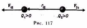
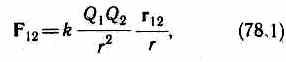
Cool law:the power of interaction F.between two fixed point charges located in vacuum,proportional to charges Q 1 and Q 2 and inversely proportional to the square of the distance r. between them:
where k.- proportionality coefficient, depending on the choice of units.
Force F. Directed in a straight line connecting interacting charges, i.e. is central, and corresponds to attraction ( F.<0) в случае разноименных зарядов и отталкиванию (F.\u003e 0) in the case of charges of the same name. This power is called coulomb force.
In vector form, the law of the coulon has the form
where F. 12 - force acting on the charge Q 1 by charge Q 2, r. 1 2 - radius vector connecting the charge Q 2 with charge Q 1, r \u003d. |r. 12 | (Fig. 117). On the charge Q 2 on the side of the charge Q 1 there is a force F. 21 =-F. 12, i.e. the interaction of electrical point charges satisfies the third Newton's law.
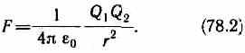
In si proportionality coefficient is equal
k \u003d 1 / (4 0).
Then the law of Kulon will be recorded in final form:
The value 0 is called electrical constant;it applies to the number fundamental physical constantsand equal
0 \u003d 8.85 10 -12 KL 2 / (n m 2),
0 \u003d 8.85 10 -1 2 F / M, (78.3)
where farad(F) - unit of electrical capacity (see §93). Then
1 / (4 0) \u003d 9 10 9 m / f.
§ 79. Electrostatic field. Electrostatic field tension
If in the space surrounding the electric charge, make another charge, then the Coulomb force will act on it; So, in space surrounding electrical charges, exists force field.According to the ideas of modern physics, the field really exists and along with a substance is one of the forms of the existence of matter, through which certain interactions are carried out between macroscopic bodies or particles that are part of the substance. In this case, they say the electric field - the field by which electrical charges interact. We will consider electric fields that are created by fixed electrical charges and are called electrostatic.
To detect and experienced the electrostatic field is used test point positive charge -such a charge that does not distort the field under study (does not cause the redistribution of charges that create the field). If in the field created by charge q, put the test charge Q 0, then the power is valid F., varied in different points of the field, which, according to the Culon law (78.2), is proportional to the test charge Q 0. Therefore, the attitude F./ Q 0 does not depend on Q 0 and characterizes the electric field at that point where the trial charge is. This value is called tension and is the power characteristic of the electrostatic field.
Electrostatic field tensionat this point there is a physical value determined by the force acting on a single positive charge placed in this field:
E.=F./ Q 0. (79.1)
in vacuum
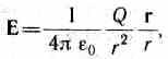
or in scalar form
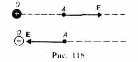
Direction of vector E. coincides with the direction of force acting on a positive charge. If the field is created by a positive charge, then vector E. directed along the radius-vector from charge to the external space (repulsion of a test positive charge); If the field is created by a negative charge, then vector E. Directed to the charge (Fig. 118).
From formula (79.1) it follows that the unit of tension of the electrostatic field - Newton to the pendant (N / CL): 1 N / CL - the intensity of such a field, which to the point charge 1 CL acts with force in 1 H; 1 N / CL \u003d 1 V / m, where in (volts) is the unit of the potential of the electrostatic field (see §84).
Graphically electrostatic field are depicted using lines of tension- lines tangents to which at each point coincide with the direction of the vector E. (Fig. 119). Intensity lines are attributed to the direction coinciding with the direction of the tension vector. Since in each given point of space, the vector of tension has only one direction, then the line of tension never intersect. For uniform field(when the vector of tension at any point is constant
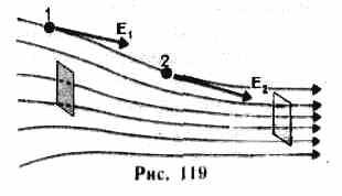
the magnitude and direction) of the line of tension is parallel to the tension vector. If the field is created by a point charge, then the line of tension is radial straight, emerging from charge, if it is positive (Fig. 120, a), and included in it, if the charge is negative (Fig. 120, b). Due to great clarity, the graphic method of representing the electric field is widely used in electrical engineering.
In order for using tension lines, not only the direction, but also the value of the electrostatic field intensity, it was agreed to carry out them with a certain density (see Fig. 119): The number of tension lines that permeate the unit of the surface area, perpendicular to the intensity lines, should be equal to the module Vectors E. Then the number of tension lines that permeate the elementary platform DS, Normal n. which forms angle with a vector E.well E.dSCOS \u003d. E. p dS,where E. n. - projection of vector E. On Normal n. To the DS platform (Fig. 121). Value
dF E \u003d E. n. ds \u003d E.d. S.
it is called the stream of tension vectors through the DS platform. Here D. S. \u003d\u003d ds. n. - vector, the module of which is DS, and the direction coincides with the direction of normal n. To the site.
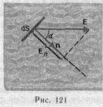
Selection of direction vector n. (and therefore S.It is conditional, since it can be directed to any side.
Unit of the flow of the electrostatic field intensity - 1 in m.
For an arbitrary closed surface S.stream vector E. through this surface
where the integral is taken over the closed surface S. vector stream E. is an algebraic value:depends not only on the field configuration E., but also from the choice of direction p. For closed surfaces for a positive direction of normal, the Normal is accepted external normali.e. Normal directed by the outside area covered by the surface.
In the history of the development of physics there was a struggle of two theories: long-range effects and closeness. In the theory of long-range, it is assumed that electrical phenomena are determined by the instantaneous interaction of charges at any distances. According to the theory nearbyAll electrical phenomena are determined by changes in charge fields, and these changes are distributed in space from point to point with a deadline. With regard to electrostatic fields, both theory give the same results that are well-consistent with the experience. The transition to the phenomena due to the movement of electrical charges leads to the insolvency of the theory of long-range theory, therefore the current theory of interaction of charged particles is theory of closestream.