Automatic switches are designed to conduct current in normal modes and automatically turn off the protected circuit in case of short circuits (SC) and overloads, as well as for operational infrequent shutdowns.
Unlike high-voltage circuit breakers, the design of which contains contact, arc-extinguishing and drive systems and does not contain devices for measuring and monitoring the protected circuits (these devices are performed at low voltage in the form of separate devices), low voltage circuit breakers, as a rule, contain both structural units and devices for measuring and monitoring the set parameters of the protected circuit.
Designs, characteristics and protective functions circuit breakers very diverse. However, according to their purpose and design principles, they can be divided into switches general purpose, high-speed and special.
Automatic switches for general purposes. These switches, according to the nature of the main circuit current, are ac, dc, ac direct current.
By their own tripping time, the switches can be current-limiting and non-current limiting.
Total duration short circuit tsc., (Fig. 4-1, a and b) consists of three terms:
to - the time from the beginning of the short circuit until the moment when the current reaches the value Iset, at which the switching device is triggered in the stationary mode;
toff ~ own shutdown time - the time from the moment the current reaches the setting value until the moment the contact diverges;
tr is the duration of the arc extinguishing process.
The time to depends mainly on constant circuit... Time toff determines the speed of the switch.
Current limiting switch - circuit breaker, which has its own shutdown time such that in this circuit during this time the current does not have time to reach the steady-state value of Isc. and the breaking current Ioff is less than that which would be in the circuit in the absence of a switch or with a non-current-limiting switch (Fig. 4-1, a). In fig. 4-1, as an example, the current limiting characteristics of some A-3700 series circuit breakers are given. Here Ic.z. - possible short-circuit current; Ioff - current to be disconnected by the switch (limited); straight 1 - current that would trip the non-current limiting switch.
Figure: 4-1. Short circuit shutdown process: a - non-current-limiting switch; b and c - current-limiting switch.
Non-current limiting switches can be with or without time delay in the zone of short-circuit currents. The first ones are designed to implement selective protection, the essence of which is that at a current Isc. (Fig. 4-2), exceeding the setting current Iyct of the switches of all stages, the section closest to the accident site is disconnected, in which the switch has a shorter time delay t1 (t1
Automatic high-speed switches (until now these are DC switches). The switches are designed to protect semiconductor converters, electrical machines and direct current lines against short circuits, overloads and reverse currents in industrial installations (for example, in electric drives of rolling mills) and in installations of mainline, industrial and urban electrified transport.

Figure: 4-2. Power protection circuit.
In these modern installations, in particular in installations with semiconductor converters, short-circuit currents reach 200-300 kA. Semiconductor devices, unlike electrical machines, do not allow overloads. Due to their nature, their Joule integral is much lower than that of electric machines and other electromechanical devices. All this requires an accelerated shutdown of the emergency section and limitation of the current in the circuit.
One more very important circumstance should be taken into account - the presence of enormous electrodynamic forces arising at the indicated currents. For example, in a circuit in which the short-circuit current can reach a steady-state value of 300 kA, at an initial speed (slope) of rise of 4.5 106 A / s, a switch with a tripping time toff = 0.08 s it is necessary to turn off the current 280 kA, at toff \u003d 0.04 s - the current 160 kA, and the high-speed switch with toff \u003d 0.005 s - the current about 22 kA. Electrodynamic forces are limited here 50-150 times.
According to the protective characteristics of our standards (GOST 2585-81 E), the proper opening time of a high-speed circuit breaker, depending on the breaking current and its rise rate, is regulated: 1st class - up to 0.008 s, 2nd class - up to 0.005 s, 3rd class - up to 0.002 s.
On alternating current rated currents in installations are limited due to the transition to a higher voltage - at 220, 380 and 660 V and currently at 1140 V. The increase in the capacity of installations sets the task of creating high-speed switches and alternating current.
Drive unit. The drive is used to close the circuit breaker at someone's command (operator, automatic control system, etc.). Switches are made with a manual or motor drive, or with both. A motor drive is understood as a drive in which the force is generated by any kind of energy, except for the muscular energy of the operator, for example, an electromagnet, electric motor, pneumatics, hydraulics, etc. The circuit breaker is tripped by springs after the release device is disconnected.
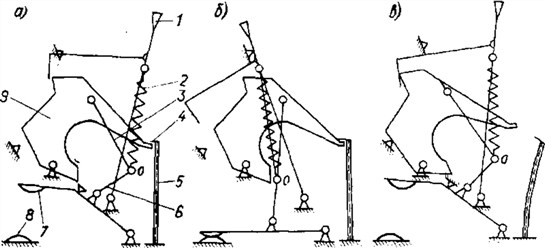
Figure: 4-3. An example of a tripping device for a circuit breaker
Trip device. This device is intended:
to exclude the possibility of holding the contacts of the switch in the on position (with a handle, a remote drive) in the presence of an abnormal operating mode in the protected circuit;
to ensure instant disconnection, i.e., independent of the operator, the type and mass of the drive, the contact divergence speed.
The release device is a system of articulated levers connecting the closing drive with a system of moving contacts, which are connected to the opening spring. The principle of operation of the device can be explained by the diagram in Fig. 4-3.
The diagram in Fig. 4-3, and corresponds to the position "Opened manually" and "Circuit breaker charged". "Cocked" means that contacts 7 and 8 are open, and the figured lever 9 is put under engagement 4 shut-off roller 5; this is done by turning the handle 1 to the right. When the handle is turned to the left, the disconnecting spring 2 will transfer the "breaking" levers 3 and b through the dead position until the hinge stops ABOUT into lever 9 and close the contacts. The “on” position is shown in fig. 4-3.6.
In the event of abnormal operating conditions in the protected circuit, the corresponding release will rotate the tripping roller and disengage it with the shaped lever. Under the action of the opening spring, the figured lever will turn and with its other end will move the “breaking” levers to the right through the dead position. The opening spring will "break" the levers and open the contacts. The switch will be in the "Disconnected automatically" position (Fig. 4-3, c). To re-enable, it is necessary to move the handle to the right and engage the curly lever with the shut-off roller.
The designs of the trip devices are very diverse, but their operation is similar to that described. In the following, the release device will be shown schematically in the form of two coupled levers.
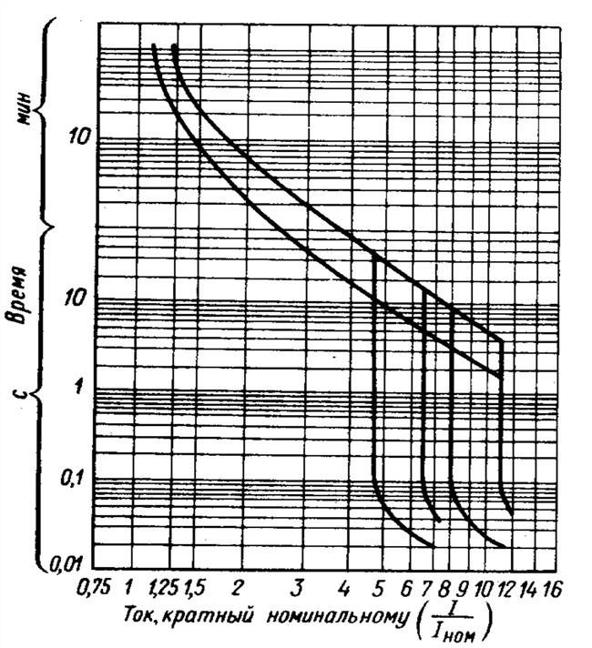
Figure: 4-4. Time-current characteristic of the BA51 series circuit breaker
One very important circumstance should be noted. Opening and contact springs in circuit breakers develop forces of tens and hundreds of Newtons. The release lever system is designed so that little force is required to release. This allows for lightweight and highly sensitive releases.
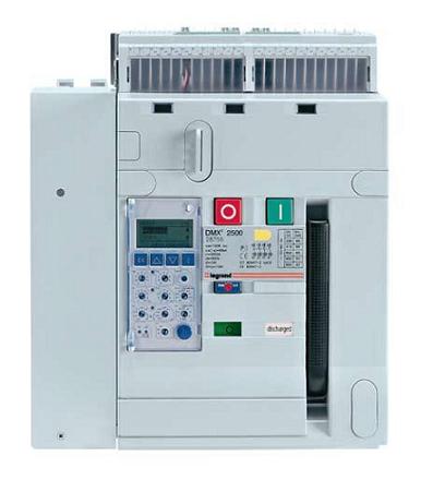
Releases. These are elements that control the set parameter of the protected circuit and, acting on the tripping mechanism, open the circuit breaker when the parameter value deviates from the set one. They are relays or relay elements built into a switch using its elements or adapted to its design. The releases are based on electromechanical relays. Currently all greater application find releases based on principles or on the basis of static relays and their elements. In this case, the controlling and comparing organs of the release are performed on semiconductor elements with an output to an independent electromagnetic element (actuator) that acts on the release mechanism.
Circuit breakers are usually equipped with an overcurrent release for protection in the area of \u200b\u200boverload and short-circuit currents or only short-circuit currents. Electromechanical releases are made by electromagnetic, electrothermal or combined. An overcurrent release based on static relays consists of a semiconductor unit (BCP), measuring elements built into each pole of the circuit breaker, and an output electromagnetic element. Measuring elements are current transformers on alternating current, and shunts or direct current transformers on direct current. Regardless of the principle of the device, the releases can be performed without time delay when tripping, with a time-independent of the current, with an inverse time-delay of the current. A typical time-current characteristic of a modern circuit breaker is shown in Fig. 4-4. A semiconductor release, which is more complex in design, allows for more favorable time-current characteristics. An example of the circuit and device of such a release is discussed below, in section 4.
The circuit breakers can be additionally equipped with releases:
independent - for remote disconnection of the circuit breaker when the corresponding voltage is applied to the release;
undervoltage or zero voltage - to automatically disconnect the circuit breaker when it drops below a certain level or when the voltage disappears.
There may be other types of releases.
The circuit breaker with instantaneous overcurrent release is shown in Fig. 4-5, a. Busbar 1 the pole of the switch covers the magnetic circuit, consisting of a core 2 and an armature 3. When the current rises above a certain value, the traction force exceeds the force of spring 5, the armature will be attracted and turn the shut-off roller 4. The trip device will be released. The switch will turn off. The actuation current is regulated by spring preload 5.
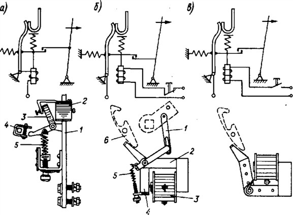
Figure: 4-5. Examples of circuits of some electromechanical releasers.
Undervoltage release (Fig. 4-5, b) consists of an electromagnet - core 2, an armature 4 and coils 3, connected to the controlled voltage. In normal modes, the anchor is pulled. When the controlled voltage drops below a certain value (setpoint), the armature, under the action of the adjusting (which is also the opening) spring 5, will fall off and, acting on the trip device through the latch b, will open the circuit breaker. The magnetic system of the release is designed in such a way that the MMF of the coil at the rated voltage is insufficient to attract the armature, but sufficient to hold it. The armature is attracted when preparing the breaker for closing using levers 1, connected to the breaker shaft.
An independent voltage release (Fig. 4-5, c) is an electromagnet that attracts its armature when the coil is turned on to the corresponding voltage. At its end, the armature acts on the trip device and opens the circuit breaker.
An example of the design of a combined (electric thermal and electromagnetic) release is shown in Fig. 4-6. In case of overloads, an electrical thermal release is triggered: bimetallic plate 2 bends due to heating and a screw 3 turns the shut-off roller 4. In the event of a short circuit, an electromagnetic release is triggered, consisting of a core 7 and an armature 5, covering the conductor 6. The electromagnetic release acts on the same tripping roller. To limit the current through the bimetallic plate, a shunt is used 1.
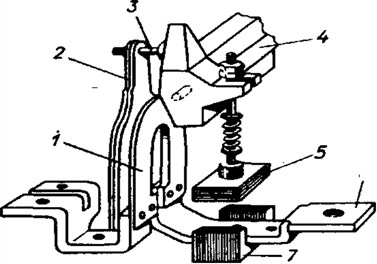
Figure: 4-6. Scheme of a combined (electrothermal and electromagnetic) release.
They can be equipped with the following built-in releases:
Electromagnetic or electronic overcurrent release of instant or delayed action with a time delay practically independent of the current;
Electrothermal or electronic inertial overcurrent release with current-dependent time delay;
Leakage current release;
Undervoltage release;
Reverse current or reverse power release;
Shunt release (circuit breaker remote opening).
The first two types are installed in all three poles, the rest - one per circuit breaker. The setting currents as well as the time delays of the current releases can be adjustable. One circuit breaker can use one or several types of overcurrent releases and, in addition to them, an undervoltage release, a shunt release and a closing solenoid.
According to the response time, electromagnetic and similar electronic releases have four types:
Releases that provide AB operation for a time much less than 0.01 s, and short-circuit current switching off before it reaches its shock value. Such ABs are called current limiting ones.
Releases providing short-circuit current interruption at the first current passage through zero tc \u003d 0.01s.
Non-adjustable releases, the operation time of which exceeds 0.01s;
Releases with adjustable time delay (0.1-0.7 s), allowing to achieve slow operation relative to other AVs of the same network, are called selective.
Leakage current releases are used to quickly disconnect sections of the network in which, due to insulation failure or people touching conductors, an earth leakage current has arisen. In this case, the setting current of the release is selected in the range from 10 to 30 mA, and the time of dependence on the voltage in the range from 10 to 100 ms. This protection is now considered more effective in protecting people from electric shock.
Undervoltage releases are used to disconnect power supplies when they stop supplying power to the network (before ATS) _, as well as to disconnect electrical receivers, the self-starting of which is undesirable when the voltage is automatically restored. The trip voltage of the release is selected in the range from 0.8 to 0.9 Un, the trip time is in accordance with the requirements of the automatic recovery systems of the mains power supply.
Shunt releases are used for local remote and automatic disconnection of AB when external protective devices are triggered.
Reverse current or reverse power releases are used to protect generators operating on electrical system from the loss of synchronicity.
17. Maximum current directional protection (principle of operation, electrical circuit diagram, calculation of time delays).
Directional current protection of the MTNZ line
T 1\u003e t → 2\u003e t 3
I p \u003d I` kz I p \u003d I` kz
U p \u003d U in U p \u003d U in
φ p \u003d 180 - φ a φ p \u003d φ a t 4\u003e t ← 3\u003e t 2
I p \u003d I,, kz I p \u003d I` kz
U p \u003d U in U p \u003d U in
φ p \u003d φ a φ p \u003d 180 - φ a
The Q1 - Q3 switches have directional overcurrent protection. It differs from the usual MTZ in that an additional body is introduced that determines the direction of the short-circuit power - a power direction relay, which reacts to the short-circuit current phase relative to the voltage on the substation buses at the place where the protection kit is installed, then the "-" sign of the power and the power direction relay blocks the set protection. If the direction of the short-circuit power is from the buses to the line, then this is a "+" sign of the short-circuit power and the power direction relay, closing its contact, allows the MTNZ set to operate.
As a result of action of directional protection 2 and 3, the set does not need to be coordinated, because they are decoupled with directional relay action This page violates copyright
Topic: what types are divided into electric machines, their types and classification.
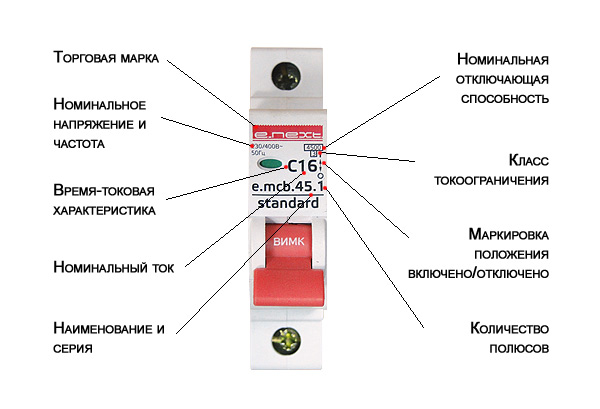
A circuit breaker is an electrical device, the main purpose of which is to switch its operating state when a certain situation occurs. Electrical machines combine two devices in themselves, this is a conventional switch and a magnetic (or thermal) release, the task of which is to timely break the electrical circuit in case the current threshold is exceeded. Circuit breakers, like all electrical devices, also have various varieties, which divides them into certain types. Let's take a look at the main classifications of circuit breakers.
1 "Classification of machines by the number of poles:
A) single-pole machines
b) single-pole circuit breakers with neutral
c) two-pole machines
d) three-pole machines
e) three-pole circuit breakers with neutral
f) four-pole machines
2 "Classification of automatic machines by type of release.
The design of various types of circuit breakers usually includes 2 main types of releases (breakers) - electromagnetic and thermal. Magnetic are used for electrical protection against short circuits, and thermal breakers are intended mainly for protection electrical circuits for a certain overload current.
3 "Classification of breakers for tripping current: B, C, D, (A, K, Z)
GOST R 50345-99, according to the instantaneous release current, the machines are divided into the following types:
А) type "B" - over 3 In up to 5 In inclusive (In is the rated current)
b) type "C" - over 5 In up to 10 In inclusive
B) type "D" - over 10 In up to 20 In inclusive
Vending machine manufacturers in Europe have a slightly different classification. For example, they have an additional type "A" (over 2 In to 3 In). Some manufacturers of circuit breakers also have additional tripping curves (ABB has circuit breakers with K and Z curves).
4 "Classification of machines by the type of current in the circuit: constant, variable, both.
Rated electric currents for the main circuits of the release are selected from: 6.3; ten; 16; twenty; 25; 32; 40; 63; one hundred; 160; 250; 400; 630; 1000; 1600; 2500; 4000; 6300 A. Also, in addition to produce machines for rated currents of the main electrical circuits of machines: 1500; 3000; 3200 A.
5 "Classification by the presence of current limitation:
a) current-limiting
b) non-current limiting
6 "Classification of automatic machines by type of release:
A) with overcurrent release
b) with a shunt release
c) with a minimum or zero voltage release
7 "Classification of machines according to the time delay characteristic:
A) without time delay
b) with a time delay independent of the current
c) with a time delay, inversely dependent on current
d) with a combination of these characteristics
8 "Classification by the presence of free contacts: with and without contacts.
9 "Classification of machines according to the method of connecting external wires:
A) with rear connection
b) with front connection
c) with combined connection
d) with universal connection (both front and rear).
10 "Classification by drive type: with manual, motor and spring.
P.S. Everything has its own varieties. After all, if there was only one thing in its single copy, it would be at least just boring and too limited! So the diversity and good that in it you can choose exactly what the maximum meets your needs.
So that all equipment in the house or at work is protected from voltage surges electric current you need to install special circuit breakers. They will be able to capture the surge and quickly react to it by disconnecting the entire system from the electricity supply. A person cannot do this on his own, but an automatic machine of a certain type can handle it in a few seconds.
Types of machines
Machine sensitivity
Before you get acquainted with the types of machines, you need to find out with what sensitivity the devices are suitable for home use, and which ones will be inappropriate. Such an indicator will indicate how quickly the device will respond to a voltage surge. It has several markings:
Classification of machines
Allocate different kinds machines in relation to the type of current, rated voltage or current indicator and other technical specifications... Therefore, you need to specifically understand each item separately.
Current type
In relation to this characteristic, the machines are divided into:
- For operation in AC mains;
- For work in a DC network;
- Universal models.
Everything is clear here and no additional explanations are needed.
In terms of rated current
The value of this characteristic will depend on the network with what maximum value the circuit breaker can operate. There are devices that are capable of operating from 1 A to 100 A and more. The minimum value with which you can find machines on sale is 0.5 A.
Indicator of rated voltage
This characteristic indicates with what voltage this type of circuit breakers can work. Some can work in a network with a voltage of 220 or 380 volts - these are the most common options for domestic use. But there are machines that will perfectly cope with higher rates.
By the ability to limit the flow of electricity
According to this characteristic, there are:
Other characteristics
The number of poles can be from one to four. Accordingly, they are called single-pole, double-pole, and so on.
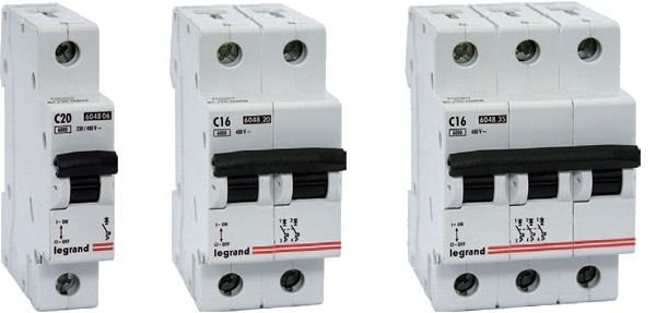
Automatic machines by number of poles
By structure, they are distinguished:
According to the rate of dropping, high-speed, normal and selective devices are produced. They can be set to a time delay function that can be inversely dependent on current or not dependent on it. The time delay may not be set.
The machines also have a drive, which can be manual, connected to a motor or a spring. The switches are widespread and the presence of free contacts, and the method of connecting the conductors.
An important characteristic will be protection against exposure environment... Here we can highlight:
- IP protection;
- From mechanical stress;
- Current conductivity of the material.
All characteristics can be combined in various combinations. It all depends on the model and manufacturer.
Switch types
The machine inside contains a release that, using a lever, latch, spring or rocker arm, can instantly disconnect the network from the electricity supply. The types of circuit breakers and are distinguished by the type of release. There are:
Circuit breakers are much more profitable than fuses. This is because after cooling, the machine can already be turned on, and it will work as it should if the cause of the overload is eliminated. The fuse must be replaced. It may not be at hand and replacement may take a long time.


