Neutrals (neutral points) of electrical installations are called the common points of the phases of the windings of generators and transformers connected in a star. The neutral can be isolated from earth, connected to earth via a re active resistanceand also directly grounded. The type of connection between neutrals and ground is determined by the safety of maintenance of electrical installations, the reliability of power supply to consumers and efficiency.
Depending on the neutral mode, electrical networks are divided into four groups:
Networks with ungrounded (isolated) neutral points;
Networks with resonant-grounded (compensated) neutrals;
Networks with effectively grounded neutrals;
Networks with grounded neutrals.
and) Networks with isolated neutral.
They are three-wire networks alternating currentwhere the source, power line and receivers are not normally connected to earth. Due to the imperfection of the insulation of the conductors, there is some leakage of currents to the ground, which can be conditionally displayed by the active insulation resistances of each phase,, (Fig. 1, a). In addition, the conductors of each phase and ground can be considered as capacitor plates, which correspond to capacitance,, and capacitance,,. The corresponding resistances are star-connected, the neutral point is ground. Capacitive currents passing through resistances to ground create voltage drops, i.e. there are phase voltages of wires relative to the ground:,,
In normal operation, the voltages,, are symmetrical and equal to the phase voltage of the consumer, and the capacitive currents of the phases,, are also symmetrical. In this case, the capacitive phase current
![]() (1)
(1)
where is the phase capacitance relative to ground. The geometric sum of the capacitive currents is 0 and therefore the current does not flow through the ground (Fig. 1, b):
![]()
In the event of a ground fault of one of the phases of the network, for example, phase A, the voltage of this phase relative to the ground becomes zero (the ground surface at the point of damage takes the potential of this phase), and the voltages of the undamaged phases (B and C) relative to the ground increase by times, i.e. .e. become equal to line voltages (Fig. 2)
Accordingly, the capacitive currents of these phases also increase in times. The single-phase earth fault current at the fault location is determined by the expression
![]() (2)
(2)
those. increases by 3 times compared to the capacitive current in normal mode
According to (3), the current depends on the mains voltage, its frequency ω and the phase capacitance relative to the ground, which depends mainly on the design of the mains line and their length. The current, A, can be approximated by the following formulas:
for overhead lines ![]() ,
,
where - line voltage of the network, kV
l- length of electrically connected network sections of a given voltage, km.
From the vector diagram, it can be seen that with single-phase ground faults in networks with an isolated neutral, the line voltage triangle is not distorted, therefore, consumers connected to line voltage continue to work normally. At the same time, it should be noted that when the network operates with a phase closed to the ground, it becomes more likely that the insulation of the other phase will be damaged and the occurrence of phase-to-phase faults through the ground. In this regard, in networks with isolated neutral, special signaling devices must be provided to notify personnel about the occurrence of single-phase ground faults.
According to the PUE, the permissible duration of operation with a grounded phase in most cases should not exceed 2 hours.
Due to the fact that in case of single-phase earth faults, the phase voltages of the undamaged phases increase to the line level, the insulation in such networks must be designed for line voltages. This limits the area of \u200b\u200busing such a mode of neutral operation by networks with a voltage of no higher than 35 kV.
The operation of the network with an isolated neutral is also used in networks with Unom≤1 kV. These networks provide a high level of electrical safety and should be used for mobile plants, peat mines and coal mines.
b) Networks with resonantly grounded neutrals .
In the event that a network with an isolated neutral has a relatively large capacitive earth fault current, namely
at 6kV Ik ≥ 30A,
at 10kV Ik ≥ 20A,
at 20kV Ik ≥ 15A,
at 35kV Ik ≥ 10A,
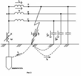
then dangerous intermittent earth faults may occur. To avoid this, according to the PUE, measures should be taken to compensate for the capacitive short-circuit current. Compensation is carried out using adjustable arc suppression reactors (inductors), which are included in the neutral of the transformers and are tuned almost in resonance with the capacitance of the network.
In normal operation, the current through the reactor is practically zero. In a single-phase short circuit, the reactor is under the phase voltage of the network and, along with the capacitive current Ic, the inductive current of the reactor I L also flows through the place of the earth fault. Since the inductive and capacitive currents are opposite in phase, they compensate each other at the point of the earth fault. If I L \u003d I C (resonance), then no current will flow through the earth fault. Due to this, the arc does not arise at the place of damage and the associated dangerous consequences... (fig. 3)
in) Networks with effectively earthed neutrals .
 In networks of 110 kV and higher, the factor of the cost of insulation is decisive in the choice of the neutral grounding method. Here, effective neutral grounding is used, in which, during single-phase short circuit (OKZ) voltage on intact phases relative to earth is ≈0.8 in normal operation. This is the main advantage of this method of neutral grounding (Fig. 4). One of the disadvantages is the significant OKZ current, which, with a large number of earthed neutrals transformers can exceed the three-phase short-circuit current. To reduce OKZ currents, if possible and effective, grounding of some neutrals of transformers in 110-220 kV networks is used.
d) Grounded neutral networks .
In industrial enterprises, four-wire three-phase networks voltage 380/220 V. Fig. 5 shows a diagram of such a network with a solidly grounded neutral, when the secondary winding is connected to a star, and the neutral point is directly (deafly) connected to the grounding device.
![]()
Motors D1 and D2 are connected to the mains phases and receive power at a line voltage U \u003d 380 V, and lamps L are connected between phase and neutral wires and are powered by a phase voltage of \u003d 220 V. In this case, the N-wire performs two functions: a working wire to which connect single-phase receivers for 220 V, and a zeroing wire, i.e. metal cases of electrical installations that are not normally energized are deliberately attached to it. In the presence of grounding, a breakdown of the insulation of the motor winding onto the case will cause a large short-circuit current and a quick protection operation ( circuit breaker QF) with disconnection of the motor from the mains. In the absence of grounding of the motor housing D2, damage to the insulation of its winding will cause a dangerous potential on the housing relative to the ground.
With a single-phase earth fault, the voltage on the intact phases relative to earth does not increase and therefore the insulation can be designed for phase, and not for line voltage.
Thus, the following neutral modes are adopted in electrical networks: 0.66-35 kV networks, depending on the magnitude of the capacitive earth fault current, operate either with an isolated neutral or with a resonant-grounded neutral; 380/220 V networks - with a dead-grounded neutral; networks 110 kV and above - with an effectively grounded neutral.
Production, transformation, transportation, distribution and consumption electrical energy carried out on a symmetrical three-phase wiring system. The symmetry of the system is achieved by the equality of the phase and line voltages, uniform loading of all phases by current, the same phase shift of voltages and currents.
However, in the process of operation, violations of the symmetry of the three-phase system are inevitable, which can be caused by: wire breakage, insulation breakdown, overlapping on foreign objects, non-phase switching of switching devices, etc.
In any case, unbalance leads to the appearance of negative and zero sequence currents, as well as an aperiodic component of currents, which can be dangerous for the safety of the equipment. Therefore, unbalance must be eliminated as quickly as possible. The operating mode of the neutral of the network has a significant influence on the speed of the relay protection in case of open-phase modes.
There are several modes of neutral operation:
- isolated,
- deafly grounded
- effectively grounded.
Each mode has its own advantages and disadvantages. In networks with voltages up to 35 kV, an insulated neutral is used. This means that the midpoint of the HV transformer windings is not connected to earth.
A single-phase fault with such a power supply system to ground does not lead to an emergency shutdown of the damaged line, since the ground fault current is quite insignificant, its value is due only to the capacitance of the two undamaged phases relative to the ground. Single-phase earth fault current, in networks up to 35 kV, is not able to maintain arc burning.
With a metallic short circuit of one phase ("full ground"), the voltage on the other two rises to linear, but the power supply to consumers is maintained in the two remaining phases. For the safety of transformers under such operating modes, the insulation of its neutral is performed for the voltage class corresponding to the insulation of the line bushings.
With significant capacitive currents of lines up to 35 kV, arc suppression coils are used, connected to the neutral of the transformers. Arc extinguishing is provided by the inductance of the coil, which compensates for the capacitive earth fault current.
An efficiently grounded neutral power supply system is considered to be a network in which part of the neutral windings of power transformers is grounded. A single-phase short circuit, in such networks, leads to disconnection of the damaged area.
The short-circuit current flows from the fault location to the nearest earthed neutrals of the transformers along the ground, being distributed in accordance with the phase-zero loop resistance. Short-circuit current (hereinafter - short-circuit) does not flow to transformers whose neutrals are not grounded.
Considering the fact that for all types of damage in electrical networks, 80% of the damage occurs in single-phase short-circuits, and the fact that close single-phase short circuits. have significant currents, they try to limit their influence.
For this, part of the neutrals in the network is left ungrounded, thereby increasing the resistance of the circuit loop and limiting the single-phase short-circuit currents. The total balance of grounded and ungrounded neutrals is calculated based on the conditions of selective operation of relay protection and automation devices and limiting short-circuit currents.
In addition, an important condition when choosing grounding points is the condition for limiting the overvoltage on the neutral windings in case of asymmetric faults. On power equipment, the neutral insulation class is usually taken one voltage class below the rated voltage of the HV windings. This practice allows you to save on insulation and equipment dimensions, which gives a high economic effect.
However, on the other hand, the reduced neutral insulation level leads to the need to use equipment that would limit overvoltages and currents in the zero terminal. Surge arresters can be used as protection against short-term overvoltages, current-limiting reactors and capacitors are used to limit currents.
In the mode of solid grounding, networks with a household consumer work. In this mode of neutral operation, the midpoint of the LV transformer windings is connected to the grounding loop. In distribution boards of residential buildings, the housing of the boards is also connected to the ground loop.
So, two wires “enter” each apartment or house: phase and zero - thereby providing the consumer with a voltage of 220 V. If the insulation of the phase wire is damaged and it touches grounded structures, the damaged network section is immediately disconnected. Concrete walls and floors in apartment buildingsalso have the potential of the earth.
The short-circuit current has sufficient values \u200b\u200bfor the operation of the protective switching equipment. IN recent times, to increase the level of electrical safety, in addition to the working zero, a protective ground conductor is also brought into the living quarters, which is connected to the enclosures of electrical appliances. The wire protective earth in the shield is also connected to grounded structures.
It should be noted that autotransformers of any voltage class always operate with a solidly grounded neutral. The insulation of the MV autotransformer windings is made based on the value of the typical power, which is less than the nominal, and therefore the insulation level is reduced. This, in fact, is the economic advantage of an autotransformer over a transformer.
With partial-phase switching of autotransformers, dangerous overvoltages arise in the electromagnetic system, which can be limited by a solid grounding of the zero terminal.
Based on the foregoing, it can be concluded that the operating mode of the neutral has a significant impact on the reliability of power supply and the operating mode of the power system as a whole.
The choice of the operating mode of the neutral of electrical installations, which, according to the conditions of electrical safety, are divided by the PUE into electrical installations with a voltage of up to 1 kV and above 1 kV, should be carried out taking into account the uninterrupted power supply of electricity receivers, the efficiency of the system, the reliability of networks, the safety of the system, the minimum power losses, the possibility of limiting switching overvoltages, reduction of electromagnetic influences on communication lines, selectivity of relay protection and ease of its implementation, the possibility of keeping the damaged line in operation, preventing the development of ferroresonance phenomena in the network, the possibility of further development of the system without significant reconstruction, etc.
In electrical networks of Russia, the following neutral operation modes are adopted:
- isolated neutral (small capacitive earth fault currents; voltage 6 35 kV and 0.4 kV);
- compensated neutral (certain excess values \u200b\u200bof capacitive currents; voltage 6 35 kV);
- effectively (dull) grounded neutral (high earth fault currents; voltage 110 kV; 0.4 kV);
Isolated neutral mode characteristic
Advantages |
disadvantages |
1. The ability of the network to operate with SPG for a limited time before taking measures to safely shutdown the damaged element |
1. The high probability of occurrence of the most dangerous intermittent arc SPZ |
2. No additional equipment and costs for neutral grounding are required |
2. High probability of secondary insulation breakdowns and the transition of the SPC to double and multiple faults due to overvoltages up to 3.5 Uph max during arc faults |
3. The ability to self-extinguish the arc and self-destruct part of the OZZ |
3. Significant (several times) increase in the effective value of the current in the place of damage in the case of alternating arc SPC due to the free components of the transient process |
4. Safety of long-term exposure to overvoltages arising in transient modes of OZZ for elements with normal insulation |
4. Possibility of significant damage to electrical machines by current in the place of damage, first of all, with alternating arc OZZ |
5. Simple (in most cases) solution to the problem of protection and selective signaling of stable SPZ |
5. Possibility of occurrence of ferroresonant processes in the network and damage to HP |
6. High degree of danger to humans and animals located near the site of the SPP |
|
7. Limitations on the size of the network development |
|
8. A high degree of interference on power lines with arc OZZ |
|
|
Characteristic of the resonant neutral grounding mode (compensated neutral) |
|
Advantages |
disadvantages |
1. The ability of the network to operate with SPC before taking measures to shutdown the damaged element |
1. Additional costs for neutral grounding through the GDR and devices for automatic control of the compensation setting |
2. Decrease in current at the place of damage (with resonant GGR tuning, the residual current contains only uncompensated active component and higher harmonics) |
2. Difficulties with solving the problem of protection and selective signaling of SPP |
3. Significant decrease in the rate of recovery of voltage on the damaged phase after the break of the arc of the current OZZ. |
3. Possibility of occurrence of intermittent arc OZZ, accompanied by overvoltages in undamaged phases up to 2.5 Ui, max |
- high-resistance and low-resistance neutral grounding (voltages 6, 10 kV).
4. High probability (taking into account clauses 2 and 3) of self-extinguishing of the arc and self-destruction of most of the OZZ (with limited values \u200b\u200bof the residual current at the place of damage). |
4. Increase in the probability of arcing intermittent 033 and maximum overvoltage on undamaged phases up to (2.6-3) Uft in case of compensation mismatch |
5. The possibility of arcing intermittent SPZs is practically excluded |
5. Possibility (subject to clauses 3 and 4) of secondary breakdowns at network points with weakened insulation |
6. Reduction of the multiplicity of overvoltages on undamaged phases in comparison with the isolated neutral (up to values \u200b\u200bof 2.5 Shnom at the first breakdown of insulation or arcing intermittent OZZ |
6. Inability to compensate (without the use of special devices) in the place of damage the active component and higher harmonics |
7. Safety of long-term exposure to overvoltages in the steady-state and transient modes of OZZ for elements with normal insulation. |
7. An increase (taking into account clause 6) of the residual current at the place of damage with an increase in the total capacitive current of the network Lm |
8. The possibility of the occurrence of ferroresonant processes in the network is excluded. |
8. Restrictions (subject to clause 7) on network development |
9. Reduction of the influence of arc OZZ on communication lines |
|
|
Characteristics of the high-impedance neutral grounding mode through |
|
Advantages |
disadvantages |
1. The ability of the network to operate with an OZZ before taking measures for the trouble-free shutdown of the damaged element (with limited values \u200b\u200bof the fault current at the place of damage) |
|
2. Possibility of self-extinguishing of the arc and self-destruction of part of the OZZ (with limited values \u200b\u200bof the OZZ current at the place of damage) |
2. Increased current at the site of damage |
3. The possibility of the occurrence of arc moving OZZ is practically excluded |
3. Possibility of occurrence of intermittent arc OZZ, accompanied by overvoltages in undamaged phases up to 2.5 C, .night |
4. Reduction of the multiplicity of overvoltages on undamaged phases in comparison with the isolated neutral (up to values \u200b\u200bof 2.5 C\u003e nom at the first breakdown of insulation or arcing intermittent OZZ) |
4. Possibility (subject to item 3) of secondary breakdowns at network points with weakened insulation |
5. Safety of long-term exposure to overvoltages in transient OZZ modes for elements with normal insulation |
5. Restrictions on the development of the network in size |
6. The possibility of the occurrence of ferroresonant processes in the network is practically excluded |
6. Harder conditions for extinguishing the arc in the place of damage compared to networks operating with an isolated neutral or with compensation of the capacitive current of the OZZ |
7. A simple solution to the problem of protection and signaling of stable SPP |
7. Large power of the grounding resistor (tens of kilowatts) and problems with ensuring its thermal stability in case of stable EPZ |
Characteristics of the low-impedance neutral grounding mode through a resistor
Advantages |
disadvantages |
1. The possibility of further development of damage is practically excluded, for example, the transition of 033 to a double earth fault or phase-to-phase short circuit (with a quick disconnection of the damaged element) |
1. Additional costs for grounding the neutral of the network through a resistor |
2. A simple solution to the problem of protection against SPL |
2. Impossibility of network operation with SPP |
3. It completely excludes the possibility of arcing intermittent OZZ (if the value of the superimposed active current) |
3. An increase in the number of disconnections of equipment and lines due to transitions of short-term self-eliminating (with arc modes of neutral grounding) insulation breakdowns into complete (completed) breakdowns |
4. The duration of the impact on the insulation of network elements of overvoltage on undamaged phases in transient modes of SPP is reduced |
4. Possibility of increasing in some cases the amount of damage to equipment (due to an increase in the current SPC) |
5. Eliminates the possibility of the occurrence of ferroresonant processes in the network |
5. Possibility of arcing intermittent OZZ at insufficiently large values \u200b\u200bof superimposed active current |
6. The likelihood of injury to people or animals by the current of OZZ in the place of damage decreases |
6. Possibility of secondary breakdowns at points with weakened insulation due to overvoltages on undamaged phases (at the first breakdown of insulation up to 2.5 Uph.nomX BEFORE tripping by the protection of the damaged element |
7. Increase in the number of disconnections of circuit breakers |
With a solid grounding of the neutral, the short circuit of one phase to earth is a single-phase short circuit, characterized by a large current. The phase voltage in relation to the ground is not higher than the phase nominal; intermittent arcs are excluded. Single-phase short circuits are automatically disconnected. The disconnection leads to interruptions in the power supply to consumers.
Another disadvantage of solid grounding of the neutral is a significant complication and rise in the cost of grounding devices. The latter is due to the fact that for a system with a large earth fault current, PUEs allow a maximum resistance of the grounding loop of 0.5 Ohm, so the number of grounding electrodes must be significant. Due to the significant single-phase short-circuit current, which may be greater than the three-phase short-circuit current, not all neutrals of the transformers are grounded dull.
Based on consideration of the advantages and disadvantages of various modes of operation of the neutral, which, to one degree or another, satisfy the requirements for neutral grounding, the following practical conclusions can be drawn.
In power supply systems with voltages of 6, 10, 20 and 35 kV, an insulated neutral is used if the capacitive currents do not exceed the values \u200b\u200bestablished by the PUE for single-phase ground faults, otherwise neutrals are used, grounded through arc suppression devices, which compensate for the capacitive earth fault current. At voltages of 6 and 10 kV, the neutrals of the generators are usually grounded through resistance. In systems with a voltage of 110, 220 kV and above, an effectively grounded neutral is used. A dead-earthed neutral at voltages up to 1 kV is used in a four-wire system with a voltage of 380/220 V, the advantage of which is the ability to supply power and lighting loads from one network, as well as in three-wire systems direct current... In three-phase systems with a voltage of 380 and 220 V, both insulated and solidly grounded neutral are used. With increased safety requirements (for mobile installations, peat developments, mines), electrical installations with an insulated neutral or an isolated source terminal are used single-phase currentif their voltage is below 1 kV, and in DC electrical installations of the same voltage, the midpoint is isolated.
Decision-making on the choice of the mode of operation of the neutral of electrical installations should be based on the recommendations of the PUE.
The neutral of an electrical installation is called the common point of the winding of a generator or transformer connected to a star. The neutral point can be isolated or grounded. This largely determines the operating conditions of the electrical installation, insulation level, short-circuit currents, and overvoltage voltages.
According to the neutral mode, electrical networks and electrical installations are divided into four groups:
Networks with isolated neutral points;
Networks with resonant-grounded neutrals;
Networks with effectively grounded neutrals;
Networks with grounded neutrals.
An electrical network with an effectively grounded neutral is a three-phase electrical network with a voltage higher than 1 kV, in which the earth-fault factor does not exceed 1.4.
Closing factor to earth in a three-phase electrical network is determined by the ratio of the potential difference between the intact phase and earth at the point of earth fault of another or two other phases to the potential difference between the phase and earth at this point before the short circuit.
Deafly grounded neutral called the neutral of a transformer or generator, connected to the grounding device directly or through a low resistance (for example, through current transformers).
An isolated neutral is the neutral of a transformer or generator that is not connected to the grounding device or connected to it through signaling, measuring, protection and similar devices with high resistance.
Grounding is the deliberate electrical connection of any point in the network, electrical installation or equipment to a grounding device.
Networks with isolated neutrals and networks with resonant-grounded neutrals include networks with a voltage of 3, 6, 10, 35 kV.
The connection of equipment windings with a delta and a star with an isolated neutral in networks creates networks with an isolated neutral.
Accordingly, in networks with isolated neutrals in normal operation, the phase voltages relative to earth are symmetrical. The capacitive component of network lines usually does not exceed 5A. In the event of an earth fault, the phase voltage rises to a linear value. Taking into account the capacitive component of the current, the voltage of the damaged phase is above zero, practically slightly less than the phase voltage, if the short circuit passes through a certain transition resistance.
Therefore, with single-phase ground faults in networks with an isolated neutral, the voltage triangle is not distorted and the consumers connected to the phase-to-phase voltage continue to work. It should be taken into account that the phase insulation must be designed for the phase-to-phase voltage. In electrical installations up to 35 kV, the cost of insulation allows a certain rise in price in relation to the cost of the main equipment of substations, since it is not decisive. At the same time, operation with a phase closed to earth at one point is dangerous by a short circuit at another point in the network. Therefore, in networks with isolated neutral, constant monitoring of insulation and signaling of its damage is required.
The operation of a network with an isolated neutral is also used at voltages up to 1 kV. These networks provide a high level of electrical safety and are used for mobile plants, peat developments and mines. For protection against breakdown of insulation between the windings of the higher and lower voltages in the neutral or in each phase of the transformer, a breakdown fuse is installed.
If in these networks the earth fault current is higher than the permissible limits, then neutral grounding is used to reduce the current in the networks through arc suppression reactors, this is a network with resonant-grounded neutrals. Arc suppression reactors L1 and L2 should be installed at nodal substations connected to the compensated network by at least three lines, Figure 2.13 shows their location. When compensating for generator voltage networks, the reactors are located near the generators.
Figure 2.13 - Connection of arc suppression reactors in networks with resonant-grounded neutrals
When connecting arc suppression reactors through special transformers or auxiliary transformers in terms of power comparable to the power of the reactors, it is necessary to take into account their mutual influence. This influence affects the decrease in the actual compensation current in comparison with the rated current due to the presence of the resistance of the transformer windings connected in series with the reactor.

where is the rated current of the arc suppression reactor,
Short-circuit voltage of the transformer,
Rated power of the transformer.
Especially sharply limiting effect of the transformer windings is manifested when using the Y / Y connection scheme, the neutral grounding is shown in Figure 2.14a. So with a single-phase short circuit to the ground, the inductive resistance is about 10 times greater than with phase-to-phase short circuits.
Therefore, it is best to connect the reactor to a Y / D transformer. But it should be borne in mind that it creates an additional load with a single-phase short circuit and leads to an increase in heating.
The permissible reactor power, provided that [email protected]
![]() .
.
where is the maximum load power.
With permissible transformer overload, the reactor power
110kV and above networks are classified as efficiently grounded neutral networks. In choosing the method of neutral grounding, the determining factor is the cost of insulation, the neutral grounding scheme is shown in Figure 2.14b.
Figure 2.14 - Grounding of neutrals in networks
a) with resonantly - grounded, b) with effectively - grounded
The use of effective neutral grounding during single-phase short-circuits creates a voltage in the serviceable phases of approximately 0.8 phase-to-phase in normal mode. This is the main advantage of such networks. Disadvantages of effective neutral grounding
1) With a single-phase short circuit, a short-circuited circuit is formed through the ground and neutral of the source with a low resistance, which creates large currents. To prevent the consequences, high-speed relay protection is required. Since most of the single-phase short circuits in such networks are self-eliminating, the use of automatic reclosing devices (AR) is effective.
2) To drain large short-circuit currents, it is necessary to construct complex grounding loops for switchgear.
3) With a large number of grounded neutrals of transformers, the single-phase short-circuit current can exceed the three-phase current. In this case, grounding of neutrals by 110-220 kV is used to reduce it.
Networks with a solidly grounded neutral are designed for voltages up to 1000V. These are networks close to technological equipment, the requirements for which are high. Three-phase and single-phase receivers in these networks are powered simultaneously. To provide power to single-phase receivers from a zero deafly grounded point, a zero working conductor is used.


