3.6. FIRE SAFETY REQUIREMENTS FOR INSTALLATION OF HEATING FURNACES AND APPLIANCES IN ROOMS
3.6.1. The laying of furnaces should be carried out taking into account the requirements of the project, and the installation of devices should be carried out taking into account the requirements of the factory instructions.
3.6.2. When laying and repairing stoves, as well as installing heating devices, the fire prevention measures in accordance with the requirements of SNiP 2.04.05-86, SNiP 3.03.01-87, GOST 9817-82, as well as albums of heating and heating-cooking furnaces recommended for use solid fuel and these Rules.
3.6.3. Combustible and hard-to-combustible structures of premises adjacent to a heating stove or apparatus must be protected from fire by arranging indentations, cutting, as well as by insulating structures with non-combustible materials.
3.6.4. Retreat, i.e. the distance from the outer surface of the furnace to the building structure can be performed completely closed, closed on both sides, closed on one side and open on all sides.
3.6.5. The dimensions of the setback and methods of protection of combustible and hard-to-burn walls and partitions, depending on the type of setback and the design features of the furnace, should be taken according to table. 3.2.
Table 3.2.
DIMENSIONS OF CLEARANCE AND METHODS FOR PROTECTING THE STRUCTURE FROM FIRE
|
Derogations |
The smallest distance between a stove or chimney and a combustible or hardly combustible wall or partition, in mm |
Ways to protect structures in deviations |
|
|
1. Heating and heating-cooking stoves with walls 120 mm thick with a periodic firebox lasting up to 3 hours. |
Open or closed on one side |
Plaster 25 mm thick. |
|
|
Closed on both sides |
A board made of boards upholstered with 8 mm asbestos cardboard or two layers of felt impregnated clay solution and faced with brick on clay mortar with a thickness of 65 mm. |
||
|
3. The same, with walls 65 mm thick |
Open on both sides |
Plaster 25 mm thick. |
|
|
4. Heating long burning |
Plaster 25 mm thick. |
||
|
5. Heating and heating-cooking stoves with walls 120 mm thick, periodic furnaces lasting more than 3 hours. |
Plaster 25 mm thick on 8 mm asbestos cardboard or felt soaked in clay mortar. Brick cladding with a thickness of 65 mm on clay mortar. |
||
|
Closed |
A board made of boards, upholstered with two layers of felt, impregnated with clay mortar and faced with brick on clay mortar, 120 mm thick. |
Notes: 1. The height and width of the insulation layer at stoves with open indentations should be 150 mm greater than their height and width, and the height of the insulation layer above the kitchen stove should be 500 mm higher than the cast iron flooring.
2. The dimensions of the indentation and the methods of protecting structures from fire in the indentations of the chimneys should be the same as for the furnaces from which smoke is removed through these pipes.
3. To protect structures from fire in open spaces, plaster should be provided on a metal mesh. Dry plastering is not allowed.
4. It is allowed to use construction felt impregnated with clay mortar, followed by plastering on a metal mesh. Mineral felt is not allowed.
5. It is allowed to use other non-combustible materials to protect structures from fire, ensuring the fire resistance of the structure is not less than 0.75 hours with an open retreat and 1 hour with a closed retreat.
6. In the buildings of secondary schools, children's preschool institutions, hostels and catering establishments, protection of structures from fire in heating and cooking ovens should be provided according to pos. 6 of this table. The layout of the gratings is shown in Fig. 3.5.
3.6.6. In preschool and medical institutions, only closed indentations should be provided, the schemes of which are shown in Fig. 3.7. On the sides of the indentation, it is sealed with red bricks, and on top, at the level of the furnace ceiling, with two rows of bricks.
Figure: 3.7. Closed retreat device
1 - furnace foundation; 2 - sealing layer; 3 - fireproof floor; 4 - wooden wall;
5 - a board made of boards; 6 - thermal insulation (asbestos or felt); 7 - brick "on the edge"; 8 - oven;
9 - pre-furnace sheet
3.6.7. For air circulation in a closed indentation, holes are made from the sides on the sides above the floor and above, and gratings are installed.
3.6.8. The floor in the retreat should be made of non-combustible materials 70 mm above the floor level of the room. A combustible floor is allowed, ensuring its protection against retreat with a fire resistance limit of at least 0.75 hours.
3.6.9. For heating furnaces long burning and frame furnaces with 65 mm thick walls, the setbacks should be made open on all sides.
3.6.10. Insulation of combustible structures in open spaces should be carried out with plaster 25 mm thick or roofing steel on 8 mm thick asbestos cardboard and go beyond the contours of the furnace by 150 mm.
3.6.11. Ceilings made of combustible or non-combustible materials above the stove ceiling must be protected from fire.
3.6.12. The minimum distance from the top of the ceiling with a thickness of three rows of bricks to the ceiling protected from fire should be 250 mm for furnaces with intermittent fireboxes and 700 mm for non-heat-consuming long-burning furnaces, and to the unprotected ceiling, respectively, at least 350 and 1000 mm.
With a two-row overlap thickness, the distance should increase by 70 mm.
3.6.13. For thick-walled stoves with a ceiling thickness of 4 bricks or more, it is allowed to close the space above the stove from all sides to the ceiling brick wallsproviding protection to the ceiling.
In the walls of the enclosed space above the stove, two openings should be provided at different levels with gratings.
3.6.14. Building structures made of combustible or hardly combustible materials and adjacent to ovens should be protected from thermal effects by cutting from non-combustible materials.
3.6.15. The dimensions of the grooves (the distance from the inner surface of the furnace to the combustible building structure), depending on the type of furnace and methods of protecting structures from fire, are given in Table. 3.3.
Table 3.3.
DIMENSIONS OF CAPACITIES FOR FURNACES AND FUMES
|
Sizes of grooves, mm |
||
|
Combustible design is not protected |
Combustible protected design: |
|
|
1. Heating and heating-cooking stoves with intermittent firebox, duration in h: |
||
|
2. Heating long burning |
||
Notes: 1. In the buildings of preschool institutions, the dimensions of the cut should be taken as for furnaces with a furnace duration of more than 3 hours.
2. The dimensions of the grooves for solid fuel boilers should be taken as for furnaces with a periodic firebox lasting more than 3 hours.
3. A combustible structure is considered to be protected from fire if its fire resistance is at least 0.75 hours.
3.6.16. The device of vertical cutting when the heating furnaces are located in the openings of combustible (hardly combustible) structures is shown in Fig. 3.8.
Figure: 3.8. Vertical cutting device
1 - oven; 2 - vertical cutting; 3 - combustible structure; 4 - thermal insulation
3.6.17. Vertical cuts are made to the entire height of the furnace within the premises, with a thickness not less than the thickness of the adjacent wall or partition.
3.6.18. Ligation of vertical cuts with the masonry of the furnace or smoke channel is not allowed, as this can cause the formation of cracks when the furnace settles.
3.6.19. Protection of combustible structures within the cut can be done with 8 mm asbestos cardboard or 20 mm thick felt moistened with clay solution.
3.6.20. When installing two-deck ovens, horizontal cuts should be performed at the intersection of the ovens with combustible floor structures.
3.6.21. Horizontal cuts are tied to the oven masonry. It is not allowed to rest the groove on the overlap. For independent settlement of the building and the furnace between cutting and building structure a gap of 15 mm is left, which is filled non-combustible materials (clay mortar with the addition of asbestos chips).
3.6.22. The height of the groove should be taken more than the thickness of the overlap so that the top of the groove protrudes 70 mm above the floor or backfill in the attic.
3.6.23. Laying wooden floor beams in the groove between the upper and lower tiers of a bunk oven is not allowed.
3.6.24. Cutting from the bottom of the ash pan and smoke pipes to the combustible floor should be carried out in three rows of bricks, providing a distance of at least 210 mm. With a non-combustible floor structure, the bottom of the ash pan and chimneys may be carried out flush with the floor.
3.6.25. A wall or partition made of combustible materials located at an angle to the front of the furnace at a distance of less than 1250 mm from furnace door should be protected from fire from the floor up to a level 250 mm above the combustion door. The protection must ensure the fire resistance of the structure is at least 0.75 hours.
3.6.26. To protect the floor made of combustible and hardly combustible materials, a 500 × 700 mm metal sheet is installed under the fire door, with its long side along the stove.
3.6.27. The combustible floor under frame furnaces and heating devices must be insulated with non-combustible materials, ensuring the fire resistance of the structure is at least 0.75 hours.
3.6.28. Solid fuel heating devices should be installed at a distance of at least 0.5 m from combustible building structures.
3.6.29. The overheated oven must be carried out in a metal case that provides strength and gas tightness.
3.6.30. Furnaces made of prefabricated concrete blocks must have expansion joints that prevent the destruction of blocks and the formation of through cracks when the furnace mass is heated during the furnace.
3.7. ORDER OF ACCEPTANCE OF OVENS AND APPARATUS
3.7.1. Acceptance of heating and heating-cooking furnaces and apparatus for solid and gaseous fuels must be carried out taking into account the requirements of SNiP 3.03.01-87 "Rules for the production and acceptance of work. Stone structures", SNiP 2.04.08-87 "Gas supply", "Safety rules in gas facilities ”,“ Rules of technical operation and safety in the gas facilities of the RSFSR ”and these Rules.
3.7.2. Heating stoves and apparatus for solid and gaseous fuels after laying (installation) must be handed over to the commission.
Solid fuel stoves and apparatus are accepted by a commission consisting of a representative of a housing and communal organization, a caretaker (commandant); the owner of the house.
Gas stoves and stoves converted from solid fuel to gas are accepted by a commission consisting of representatives of the operating organization of the gas economy (chairman), the customer, and the construction and installation organization.
3.7.3. Upon acceptance and delivery of heating furnaces and apparatus, the customer must present the commission:
a) design materials for the furnace (apparatus);
b) acts for hidden work, drawn up in the process of masonry;
c) the project of gas supply to the furnaces (apparatus), approved in accordance with the established procedure with deviations and changes made to it, made during the installation process;
d) an act of inspection of the technical condition of heating and heating-cooking furnaces intended for transfer to gas fuel;
e) act of inspection of the technical condition of smoke and ventilation ducts from furnaces (apparatus);
f) act of acceptance into operation of in-house gas equipment;
g) protocol on passing exams for knowledge of safety rules in gas facilities by commandants and managers in residential buildings and persons responsible for the gas economy at enterprises;
h) a document certifying the training of residents in the rules for the safe use of gasified ovens (devices).
3.7.4. When accepting stoves (apparatus) using solid or gaseous fuels, it is necessary to check:
a) availability of the necessary executive and technical documentation (design materials for the furnace, gas supply project, acts for hidden work, acts of checking the suitability for operation of furnaces and flue channels, an act of acceptance of gas equipment and other documents regulating the safe operation of gas equipment);
b) compliance of the work performed with the requirements of the project;
c) the quality of the masonry performed (the presence of dressing; the thickness of the seams, the verticality of the corners and walls; the careful fit of the tiles; the presence of cracks);
d) the density of the oven masonry;
e) the presence of sufficient devices for cleaning the oven;
f) the size of the cuts or indentations in the furnaces and the method of protecting combustible structures from fire;
g) the presence and operability of automatic devices that ensure the shutdown of the burners when the gas supply stops, the flame goes out and there is no necessary vacuum in the smoke channel;
h) the quality and strength of the installation of furnace devices;
i) the procedure for laying connecting pipes (nozzles) from furnaces and apparatus to smoke channels;
j) the quality of the gas pipelines performed and the procedure for laying them in the building;
k) compliance of the smoke and ventilation ducts with the requirements set forth in Chapter 5 of these Rules.
3.7.5. When accepting and handing over the furnace works, it is necessary to carry out a control furnace in the presence of the customer and the contractor. If there are a large number of identical furnace designs, multiple furnaces are tested for choice.
Test firing of gasified furnaces is carried out after the start-up of gas by specialists of the gas industry.
3.7.6. In a test furnace, set:
a) temperature and uniformity of heating of the furnace walls;
b) the presence of traction in the furnace and smoke channels;
c) the absence of bursting in the masonry of the furnace and channels;
d) no condensation in the smoke ducts;
e) tightness in the places of installation of valves and views.
3.7.7. The deviations of the surfaces of the oven masonry from the vertical should not exceed 10 mm over the entire height of the oven. Irregularities on the surface are allowed no more than 5 mm for stoves and pipes without lining and no more than 2 mm for lined stoves. Deviations from the design dimensions in terms of a stove, kitchen hearth or chimney should not exceed ± 10 mm.
3.7.8. The dimensions and serviceability of the cuts and the indentation between the stoves, smoke channels and wooden structures of buildings should be made by external inspection and tapping. In the event that it is impossible to establish the presence of cuts and deviations from an external examination, a control opening is performed and the subsequent careful sealing of the opened places. The autopsy results are documented in an act.
3.7.9. Furnace appliances must ensure the proper operation and maintenance of the furnaces. Doors and latches, as well as views, must close well and ensure tightness.
3.7.10. If defects are found that impede normal and safe operation furnaces, a defective statement is drawn up and a deadline for their elimination is assigned. Until the defects are completely eliminated, the operation of the furnace is not allowed.
3.7.11. For each accepted stove (or a group of identical stoves), it is necessary to draw up a passport, which indicates the date of laying the stove, notes the design features of the stove and enter the names of the performers of the work.
3.7.12. During the delivery and acceptance of the furnace work, the volume of the masonry is measured and the results of the work performed are recorded in the acceptance certificate (Appendix 1).
3.8. REQUIREMENTS FOR THE OPERATION OF FURNACES AND APPARATUS FUNCTIONING WITH SOLID FUEL
3.8.1. The operation of furnaces and apparatus is allowed subject to the safety requirements established by the "Standard fire safety rules for residential buildings, hotels, hostels, buildings of administrative institutions and individual garages" and GOST 9817-82 "Household appliances operating on solid fuel".
3.8.2. Before the start of the heating season, stoves and devices must be checked and repaired. Defective heating devices are not allowed for operation.
3.8.3. Before using the stoves, check the integrity of the masonry of the stoves and smoke channels and the condition of the firebox lining.
3.8.4. During operation, it is necessary to constantly monitor the serviceability of the shut-off and control valves, the grate, ash pan and firebox doors, and the tightness of the hatches on the smoke channels.
3.8.5. It is forbidden to overheat stoves with intermittent firing, burning fuel more than the amount for which they are designed. Furnaces must be fired twice a day,
3.8.6. In industrial, cultural, domestic, public and other office premises, the furnaces must be fired by specially designated persons who have received fire-prevention instructions and comply with fire safety rules. The firebox in these rooms must be finished 2 hours before the end of work in these rooms.
3.8.7. In childcare facilities with children staying during the day, the furnace must be finished no later than 1 hour before the arrival of the children.
In hostels, hospitals and childcare facilities with round-the-clock stay of children, the firebox must be completed two hours before the residents go to bed.
3.8.8. During public events, the heating of stoves and apparatus is not allowed.
3.8.10. It is forbidden to heat the stove with an open fire door. If the door opens spontaneously, repairs should be made.
3.8.11. It is forbidden to overfill the firebox with fuel or use firewood that exceeds the depth of the firebox in length, as well as exceed the amount of fuel burned established for each brand of stove or apparatus.
3.8.12. The approaches to the furnace from the side of the fire door must be free. Furniture and other combustible materials should be placed at a distance of at least 0.5 m from heating devices. In a heated room, it is allowed to store a supply of solid fuel for no more than one furnace.
3.8.13. When operating prefabricated heaters, use only the type of fuel for which the device is designed. It is not permitted to convert these devices from one fuel to another.
3.8.14. Firewood and peat should be used as fuel, and shale and coal cleaned of impurities.
3.8.15. When firing up and loading new portions of fine coal rich in volatile compounds, the entire combustion mirror should not be covered. If the mirror turns out to be closed, then until a flame appears in the firebox above the coal surface, it is necessary to keep the furnace door ajar with a gap of 10-20 mm to dilute the gases of the mixture to a safe concentration.
3.8.16. The boiler with a water circuit must only be operated when connected to a heating system filled with water.
3.8.17. During the heating, it is necessary to constantly monitor the temperature of the water in the circuit according to the thermometer provided by the design of the apparatus. The water temperature at the outlet of the apparatus should not exceed 90 ° C.
3.8.18. The surfaces of heating devices must be systematically cleaned of dust and other combustible deposits.
3.8.19. In summer fire hazard period during a strong wind, it is advisable to stop firing stoves and apparatus operating on solid fuels.
3.8.20. Slag and ash must be removed to a specially designated safe place and filled with water.
3.8.21. The main faults during the laying and operation of stoves and methods of troubleshooting are given in table. 3.4.
It must be remembered that a casually laid out stove always gives a large sediment with the appearance of cracks in it and chipping of the solution from the seams. Hot gases and fire penetrating through cracks and seams lead to rapid ignition of combustible structures, especially wooden ones. Fires also occur from careless burning.
The fires are also caused by the ignition of soot, which collects in the smoke channels, and from their very strong heating, the wooden structures adjacent to the stove ignite.
Therefore, all wooden parts of the building: walls, partitions, floors, ceilings and others should be removed at a certain distance from the heating surfaces of the furnace with a cutting device or indentation, that is, from the thickening of the masonry walls of the furnace or pipe. The thickness of these cuts or the distance from the "smoke" to the combustible structure should be as follows, mm:
Wooden chopped walls in the process of drying out of wood or compaction of caulk give sediment, which violates the strength of the cuts. Therefore, the height of the grooves is made to the size of the possible draft.
It is possible to insulate (close) the furnaces with reliable insulation made of non-combustible and non-heat-conducting materials: sheet asbestos or two- or three-layer felt, which does not conduct heat well and at the same time is a good thermal insulation material. When ignited, it smolders, emitting an unpleasant smell of combustible wool, which signals the danger of fire. To protect the felt from destruction by moths and to ensure minimal flammability, it is impregnated with a liquid clay solution before laying it in place.
It is forbidden to lay floors or make filing close to the walls of the root pipe or stoves; they should only reach the edge of the groove. In this case, concrete or ceramic tiles are used over the cutting.
When installing a stove between burning wooden walls or partitions, an indent of at least 130 mm is made between them, with wood insulation from the cutting side, and the distance between the wood and the "smoke" should be at least 250 mm.
Without wood insulation, this distance is increased to 380 mm.
The indentation is sometimes closed (laid) from the sides. In this case, the wooden wall is insulated with the so-called "cold quarter", that is, a wall 14 bricks thick, which is laid out on the felt.
In new houses with log or cobbled walls, given that they will give a large draft, with a closed retreat from the sides, it is necessary to install a wooden shield attached to the wall so that it slides between the fastening parts and does not interfere with the draft of the wall.
A “cold quarter” is also made on this shield over the laid felt.
Since it is practically very difficult to keep the brick on the felt, it is necessary first to lay felt on the board or wall, nail it with nails so that it does not fall off, and then lay the brick on the clay mortar, securing it with nails with put on washers or performing wire weaving on the nails. After laying, the brick is plastered with a clay or other more durable mortar (Fig. 95).
Figure: 95. Insulation of walls from the stove: 1- shield; 2 - crutch; 3 - felt; 4 - bricks; 5- washers, nailed; 6 — nails; 7 - offset 13 cm; 8 - roofing steel nailed to two layers of felt
Figure: 96. Space between the stove and the wooden wall: 1 - wooden wall; 2 - brickwork; 3 - wooden board; 4 - two layers of felt; 5 - ventilation grilles; 6 - offset 13 cm
Figure: 97. Indent between the oven and wooden partitions: 1 - wooden partitions; 2 - two layers of felt; 3 - offset 13 cm; 4 — retreat 25 cm
In the closed air gap for air circulation between the oven and the "cold quarter" at the bottom and top from the sides, holes must be made, closing them with gratings (Fig. 96). The "cold quarter" is made in height and width in indentations equal to the width and height of the oven, but not less (Fig. 97).
When the kitchen stove is in the opening of a wooden partition or between wooden walls, cutting is performed on the sides of the plate into half a brick, above the plate - into two bricks.
Vertical cuts do not allow ligation with the oven or pipe masonry, no matter what solution these cuts are made with.
It is imperative to leave a gap from the top of the ceiling to the stove overlap (overlap) of at least 350 mm, and when insulating the ceiling - 250 mm. It must be accessible for inspection, repair and dust removal. If the furnaces are heat-consuming, having a mass of up to 750 kg, then the gap is left at 350 - 450 mm, and for non-heat-consuming - 700 - 1000 mm.
Wooden ceilings above the stoves are plastered with felt or insulated with two layers of felt so that this insulation for both plaster and roofing steel is 150 mm larger on all sides than the dimensions of the stove.
If the stove is connected to the chimney using a branch pipe, then the distance to the wooden ceiling or partitions is set at least 500 mm or 380 mm if there is insulation.
The wooden floors in front of the firebox of any stove are insulated with two layers of felt and covered with a sheet of roofing steel with a size of at least 500x700 mm, covering the plinth with roofing steel.
Under kitchen hearths or stoves with legs, wooden floors must be covered with asbestos or double-layer felt insulation. The size of this insulation should be equal to or greater than the furnace on all sides by 150 mm.
Furnaces and pipes should be systematically inspected and any defects corrected immediately.
IN winter time it is especially necessary to monitor the stoves and pipes, as they are heated more.
Temporary stoves are placed at a distance of at least 1 m from combustible structures. It is strictly forbidden to put flammable materials near the firebox.
You should also pay special attention to the masonry chimneys and their maintenance in the appropriate order (see the section "Construction of chimneys").
Cuttings are placed on clay, lime, lime-cement or cement mortar... They should not be tied to the pipework and should not be as thick as the wall or partition. The usual thickness of the cuts is 14 or 12 bricks.
The adjoining part of the combustible structure to the cutting is insulated with sheet asbestos or two layers of felt. It is advisable to pre-soak the felt in an anti-mole composition. The thickness of the felt insulation must be at least 20 mm. If the felt is thin, then it is put in two or three layers.
The width of the indentation or groove is considered "from smoke", that is, from the inner surface of the stove or chimney, and is equal to 380 mm for unprotected structures from fire and 250 mm if they are protected from fire by insulation.
Often in the walls where the smoke channels pass, it is necessary to lay wooden beams (Fig. 98 |. They should be located so that between the beam and the inner surface of the channel there is a distance of at least 250 mm for chimneys from conventional stoves and 380 mm - from stoves with The ends of the beams from the side of the channel are insulated, but the ends are left open.It is more reliable to leave a distance of 380 mm between the beams, their ends and chimneys with the obligatory laying of an insulating layer.
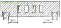
Figure: 98. Insulation of the ends of the beams in oven masonry near canals
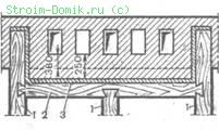
Figure: 99. Crossbar device: 1 - beams; 2 - crossbar; 3 - insulation
(felt)
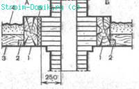
Figure: 100. Cutting fluff in the attic floor: 1 - beam; 2 - bar; 3 - knurler; 4 — backfill; 5 - insulation
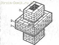
Figure: 101. Reinforced concrete slab for maintaining brick cutting:
1 - plate; 2 - cutting; 3 - riser Pipes
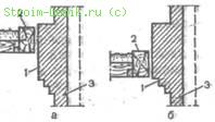
Figure: 102. The location of the fluff taking into account the slump settlement:
and - before precipitation; 6 - after precipitation; 1 - raepushka; 2 - overlap; 3 - pipe riser
Sometimes the beam has to be against the chimneys and it is impossible to carry it to one side or the other, then it is shortened and a short transverse beam is cut into the crossbar, laid, in turn, on two beams. They are fastened to each other with a dovetail thorn (Fig. 99). The ends of the beams embedded in the wall and the transom adjacent to the wall are insulated.
At the root and packing pipes, as well as at the walls in the places where the channels pass at the level of the interfloor and attic floors, in the process of laying the walls or pipes, horizontal cuts or fluffs are made, which are made during the laying of the pipe, increasing the thickness of the cut. Have brick ovens with a short-term firebox, the thickness is taken in one brick. This distance is considered from "smoke" to combustible wooden structures, which must be upholstered with sheet asbestos cardboard or two layers of felt. If there are no insulating materials, the thickness of the cut is adjusted to one and a half bricks. However, even with such a cut, insulation is needed (Fig. 100).
If stoves or kitchen hearths (stoves) are heated for more than 3 hours, then the cutting should be one and a half bricks with mandatory insulation. In the absence of insulation, the cutting is brought to two bricks.
Cutting masonry is a complicated matter, therefore, in the interfloor and attic floors, it is best to use reinforced concrete slab 50 mm thick. On this slab, after laying the riser, a groove can be easily performed (Fig. 101).
When arranging cuts, you should take into account the different settlements of the walls of the building, root pipes and furnaces. Stone walls, pipes and furnaces have a low (negligible) draft. Wooden chopped walls, especially from non-dried material, settle to an average of 150 mm. The rise and settlement of walls also occurs during window-blade. Ceilings settle along with the walls. The insulation around the cut is removed prior to commencing window-cutting work. It must be remembered that it is forbidden to support the cutting brick on the beams or flooring. During settlement, a crack may form there, causing a fire.
When the walls give rise to a draft greater than the root or packing pipes, then the cutting is performed so that it has a margin at the bottom to the inside of the room. If the root pipe and the furnace with a packing tube give a draft greater than the walls and the ceiling, then the fluff should have a margin at the top (in the attic) (Fig. 102). The attic floor is often covered with light, low-heat-conducting combustible materials: sawdust, peat, dry wood leaves, etc. From above, such materials must be covered with slag, earth, sand with a layer of 20 mm. In this case, the groove should rise above the backfill at least 70 mm, and in general the more, the better. A completely fireproof backfill with a thickness of at least 100 mm is made near it.
Wooden rafters and lathing should be at least 130 mm from the outer surfaces of brick pipes. With combustible roofs, the distance between the roof and the chimney must be at least 260 mm. The remaining gap is covered with roofing steel or asbestos-cement sheets.
when operating ovens.Wood materials ignite when heated to a temperature of 300 °, but if they are in contact with objects heated even to 100 ° for a long time, they acquire the properties of spontaneous combustion. Therefore, when installing furnaces, it is necessary to ensure that the heated surfaces of the furnaces and smoke chutes do not come into contact with the combustible parts of the building. The main requirement of fire prevention: wooden or other easily flammable parts of buildings must be at a sufficient distance from the hot parts of the stove and smoke chimneys or be well insulated.
Particularly dangerous are cracksformed in the massif of the furnace and smoke channels due to uneven settlement or crumbling clay mortar from the joints as a result of the action of high temperature. A fire can also be caused by combustion of soot accumulated in large quantities in the smoke ducts.
For insulation, non-combustible materials or materials with low thermal conductivity are used: red brick, felt, as well as asbestos in the form of sheets and a cord. Felt, which is usually made about 5 mm thick, does not conduct heat well and serves as a good insulating material. When ignited, it smolders and with a pungent suffocating odor signals a fire. To make it more resistant to fire, it is impregnated with a clay solution before laying.
When laying thick-walled heat-intensive furnaces on a combustible base minimum distance from the floor level of the room to the bottom of the ash pan should be at least 140 mm, and to the bottom of the smoke chutes - 210 mm. When installing a thick-walled heat-intensive furnace on a fireproof base, the bottom of the ash pan and all smoke flows can be laid out at floor level. In this case, the minimum distance from the floor of the room to the bottom of the last chimney of the stove must be at least 140 mm, and to the bottom of the remaining chimneys - at least 210 mm.
Wooden or other combustible floor surfaces located under frame thin-walled ovens and kitchen stoves with metal legs are insulated with 12 mm thick asbestos cardboard covered with roofing steel on top. The floors under metal furnaces made of sheet steel or roofing steel, as well as cast from cast iron, are insulated with two rows of bricks, laid on a block on a double layer of felt impregnated with clay mortar.
The floor under the furnace door of the furnace is upholstered with a metal sheet measuring 500 x 700 mm, which protects it and the plinth at the furnace wall from fire.
When installing the stove between the combustible partitions or in the opening of the wooden wall between the stove and the partitions, leave an indent of at least 130 mm wide, which is sealed brickwork... The wooden structure is carefully insulated with asbestos or felt soaked in clay mortar. The minimum distance from the inner surface of the nearest furnace smoke circulation (smoke) to wood must be at least 250 mm (1 brick). The groove width is equal to the thickness of the adjoining wall or partition of the building. When brick or non-combustible walls are adjacent to the furnace, the thickness and width of the groove is 0.5 bricks.
In all cases, when constructing a furnace or chimney near a wooden wall or partition of a building, a free air gap (retreat) is left between them at the height of the furnace or chimney. Combustible walls and partitions in the retreat are insulated with asbestos or two layers of felt impregnated with clay mortar, followed by upholstery with roofing iron. The indentation can be open or closed with bricks on one or both sides (other fire-resistant material can be used). When installing a closed indentation, it is sealed from the sides with brick walls half a brick thick. The total thickness of the open space is arranged so that the distance from the inner surface of the smoke channels to the wooden wall or partition is at least 250 mm. If the indentation is closed on both sides with a brick, it is covered with two rows of bricks or other fire-resistant material. The resulting closed chamber is provided at the bottom and top with ventilation grilles for air circulation. The cross-sectional area of \u200b\u200beach ventilation grill must be at least 150 cm 2.
For long-burning heating stoves, the width of the open gap must be at least 260 mm. Wooden walls in the retreat are plastered with lime-gypsum mortar 25 mm thick. When constructing a closed indentation for stoves with half-brick walls with a furnace duration of more than 3 hours, the wooden wall of the building is protected from fire by facing also in half-brick.
For stoves with walls a quarter brick thick, a setback is used, open on both sides. The distance between the stove and the combustible wall or partition of the building must be at least 320 mm. The retreat of non-heat-intensive furnaces is left open. Distance between metal oven without lining and a combustible wall, the building should be 1 m.For non-heat-consuming furnaces lined with bricks or fireclay slabs, this distance can be reduced to 0.7 m.In all cases, air gaps (indentations) for heat-consuming furnaces with walls 0.7 m and less left open.
A burnt floor in a retreat is protected by one row of bricks laid flat, ceramic tiles or other fire resistant material. The floor in the retreat should be 0.7 m above the floor level in the room.
When the retreat is open on one or both sides, the combustible wall or partition of the building is insulated with two layers of felt impregnated with clay mortar, followed by plastering or upholstery with a sheet of roofing steel. With a closed retreat, the wooden walls or partitions of the building are protected from fire by facing made of bricks laid on a double layer of felt soaked in clay mortar. This insulation of the walls that burns is called the cold quarter, since the thickness of the brick cladding is a quarter of the brick. Brick cladding is laid only on clay mortar. To arrange a cold quarter near a wooden chopped wall, a plank board is nailed to it, then upholstered with two layers of felt impregnated with clay mortar, over which brick is made. The quarters in the indent should be at least the height and width of the heating stoves.
The combustible wall adjacent to the stove near the furnace door is plastered or upholstered with roofing steel over felt soaked in clay mortar. The insulated area of \u200b\u200bthe wall must exceed the area of \u200b\u200bthe combustion door on the sides and bottom by 0.1 m, and at the top - by 0.25 m. The distance from the combustion door to the opposite wall must be at least 1.25 m.
For heat-consuming furnaces with a mass of 750 kg or less, the minimum distance from the upper floor (overlap) to the ceiling unprotected from fire should be at least 0.45 m.If the combustion ceiling is insulated with a layer of plaster or a sheet of roofing steel nailed over asbestos or over a double layer of felt, impregnated with clay mortar, this distance can be reduced to 0.35 m. The distance from the upper plane of overlapping heat-consuming furnaces weighing more than 750 kg to the burning ceiling should be 0.35 m, with a protected ceiling - 0.25 m.
When installing non-heat-consuming stoves, the minimum distance from the upper plane of the stove to the ceiling unprotected from ignition should be 1 m, and with an insulated ceiling - at least 0.7 m. The insulated section of the ceiling above the non-heat-consuming stove should extend beyond the dimensions of the stove overlap in all directions by 0, 15 m.
The thickness of the upper floor of a heat-intensive furnace should be at least three rows of bricks, and in a closed space from the top of the furnace to the ceiling of the room, at least four rows. The free space above the stove is covered with bricks or decorative walls made of fire-resistant materials. In the walls of the closed space above the furnace, two holes are provided at different levels with gratings, the area of \u200b\u200bthe free cross-section of each grate is at least 150 cm 2. When laying the upper ceiling of the furnace, special attention is paid to the correct dressing of the seams, not allowing them to coincide vertically.
In the interfloor and attic ceilings, where the combustible parts of the building are adjacent to the smoke channels, vertical and horizontal divisions are provided (clauses 3.81-3-83 and Appendix 16 "Dimensions of divisions and indentation at stoves and smoke channels" SNiP2.04.05-91 *, M., 1998).
|
Cuttings are also arranged in the places where the combustion structures are adjacent to the ventilation ducts, if they are located next to the smoke ducts. Horizontal cuts around the pipes near the wall flue channels and walls of the furnace are made of bricks or other heat-insulating materials by thickening the masonry along the entire height of the combustible ceiling. At the same time, between the cutting and the overlap, a gasket of spirit layers of felt impregnated with clay mortar, with a thickness of at least 20 mm, is arranged. When arranging grooves in the floors and ceilings of premises, it is necessary to constructively ensure the independence of the upsetting of walls and floors from the upsetting of the furnace and chimney. It is forbidden to rest the grooves on the structural elements of the floor. The width of the free space between the outer surface of the chimney and the wooden part of the rafters or lathing must be at least 130 mm. For easily combustible roofs (tarpaulin, tattered), the width of such a space should be at least 0.26 m.The roof in the places where the chimney passes is covered with iron, slate, roofing steel or other non-combustible materials to a width of at least 0.5 m with careful adjustment to pipe otter. Horizontal cuts in the floor plane are performed simultaneously with the main laying of the furnace or chimney. It is impossible to tie the masonry of vertical cuts, arranged near wooden walls and partitions, with the masonry of a stove or chimney. Metal and reinforced concrete beams located near the smoke ducts should be located at a distance of at least 0.13 m from their inner surface. Wooden beamspassing or embedded in the walls of the chimney should be located at a distance of at least 0.25 m from the channels. Their ends should be wrapped in two layers of felt soaked in clay mortar. If it is impossible to install the beams in compliance with the specified distance from the smoke and ventilation ducts, arrange the crossbar. The cutting of asbestos-cement chimneys at the points of adjoining to the combustible parts of the room is performed by widening the asbestos-cement riser or by creating a fireproof section of the overlap. Compliance with the rules furnace construction, fireplaces and baths, as well as fire safety rules, contributes to the creation of favorable conditions for the life of people, ensures the safety of open fires in any season, and allows them to be used with full load in accordance with the purpose of a particular structure. |
When constructing a furnace between combustible partitions or in the opening of a wooden wall between the furnace and the partitions, an indent of at least 130 mm is left, which is sealed with brickwork. Wherein wooden structure carefully insulate with asbestos or felt soaked in clay mortar. The minimum distance from the inner surface of the nearest furnace smoke circulation (smoke) to wood must be at least 250 mm (1 brick). Cutting is performed with a width equal to the thickness of the adjoining wall or partition of the building. When adjacent to the oven brick or non-combustible walls the thickness and width of the groove is 0.5 bricks (Fig. 4).
In all cases, when constructing a furnace or chimney near a wooden wall or partition of a building, a free air gap (indentation) is left between them for the entire height of the furnace or chimney (Fig. 5). At the same time, combustible walls and partitions in the retreat are insulated with asbestos or two layers of felt soaked in clay mortar, followed by upholstery with roofing iron.
4. Cutting between walls and smoke channels: 1 -; 2 - adjoining walls; 3 - cutting
The indentation can be open or closed with one sheet on both sides with brick or other fire-resistant material. When installing a closed indentation, they are closed up with brick walls 0.5 bricks thick. The total thickness of the open indentation is arranged in such a way that from the inner surface of the smoke channels to a wooden wall or partition is at least 250 mm. If the indentation is closed on both sides with a brick, then the top of the open indentation is covered with two rows of bricks or other fire-resistant material. The resulting closed chamber at the bottom and top is equipped with ventilation grilles to ensure air circulation. the free area of \u200b\u200beach grid must be at least 150 cm2 (Fig. 6).
6. The device of a closed retreat: 1 - ventilation grilles; 2 - sealing the air gap 0.5 brick thick
For long-burning heating stoves, the width of the open gap must be at least 260 mm. Wooden ones in retreat are plastered with lime-gypsum mortar with a layer thickness of 25 mm. When constructing a closed indentation for stoves and kitchen stoves with walls 0.5 bricks thick for a duration of more than 3 hours, the wooden wall of the building is protected from fire by facing 0.5 bricks.
For apartment-type stoves with walls 0.25 brick thick, a retreat is used, open from the sides. In this case, the distance between the furnace and the combustible wall or partition of the building must be at least 320 mm.
For non-heat-consuming stoves, the retreat is left open. The distance between the metal furnace without lining and flammable wall the building should be 1 m.For non-heat-consuming furnaces lined from the inside with bricks or fireclay plates, this distance can be reduced to 0.7 m.
In all cases, the air gaps (setbacks) of non-heat-consuming furnaces with walls 70 mm thick or less are left open.
A combustible floor in a retreat is protected by one brick laid on a block, ceramic tiles or other fire-resistant material. The floor in the recess should be 70 mm higher than the floor in the room.
With one or both sides open combustible wall or the building partition is insulated with two layers of felt impregnated with clay mortar, followed by plastering or upholstery with a sheet of roofing steel.
With a closed retreat, the wooden walls or partitions of the building are protected from fire by facing made of bricks laid on a double layer of felt soaked in clay mortar. This insulation of combustible walls is called cold quarter, since the thickness of the brick cladding is 0.25 bricks. The laying of brick cladding is performed on clay mortar.
To arrange a cold quarter near a wooden chopped wall, a plank board is nailed to it, and then it is knocked out with two layers of felt impregnated with clay mortar, over which brick is lined (Fig. 7). Cold quarters in indentation should be at least as large as the height and width of the heating stoves. When constructing apartment-type kitchen hearths near a wooden wall of a building, the height of the cold quarter is performed 0.5 m above the kitchen hearth.
7. Arrangement of a cold quarter in a closed indentation: 1 - a wooden wall of bars; 2 - a board 80 mm thick; 3 - felt impregnated with clay solution (two layers); 4 - on
The combustible wall adjacent to the stove near the furnace door is plastered or upholstered with roofing steel over felt soaked in clay mortar. The insulated area of \u200b\u200bthe wall must exceed the area of \u200b\u200bthe fire door on the sides and bottom by 100 mm, and by 250 mm. The distance from the furnace door to the opposite wall is not 1.25 m.
For heat-consuming furnaces with a mass of 750 kg or less, the minimum distance from the upper overlap (overlap) of the ceiling unprotected from fire must be at least 450 mm. combustible is insulated with a layer of plaster or a sheet of roofing steel nailed on asbestos or on a double layer of felt impregnated with clay mortar, this distance can be up to 350 mm.
The distance from the upper plane of the ceiling of heat-consuming stoves weighing more than 750 kg to the ceiling should be 350 mm, and with a protected ceiling. 260 mm.
When installing non-heat-consuming stoves, the minimum distance from the upper plane of the stove to the ceiling unprotected from fire should be 1 m, and with an insulated ceiling - at least 0.7 m.
| Our archives! | · · · · · · : · · · · · · · · · · · · |


