To ensure your own a private house A secure power supply system is necessary in the process of its reconstruction or when a new electrical layout scheme take into account the grounding system. At the same time, it should be noted that the installation of a grounding in a private house with its own hands is 220V - the process is not very complex. Especially if compared with installation in apartment house. And although everyone understands, why need a protective grounding, not all do it. Therefore, we will consider the design completely, and at the same time they will answer the question of how to make the contour of the country house.
Grounding device outside at home
The grounding circuit device in a private house is a pin, driven into the soil vertically, which are tied with each other. And the whole design is connected to the distribution shield in the house. Before making grounding in a private house, you must prepare required tools and materials.
The tools will need shovels, scrap, sledgehammer, hammer, welding machine with electrodes, Bulgarian, spanners. From materials:
- metal corner with dimensions 50x50x5 mm;
- steel tape with a width of 40 mm and 4 mm thick;
- metal wire rolling with a diameter of 8-10 mm.
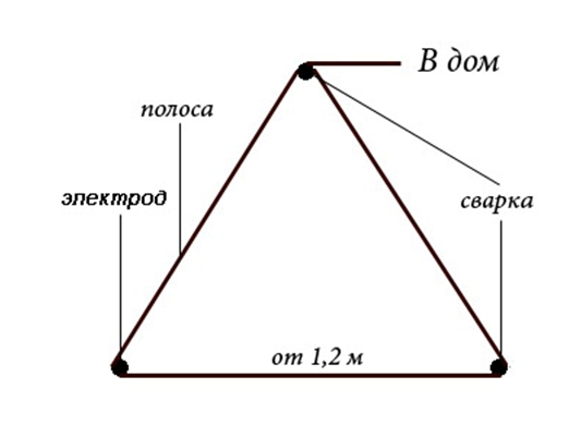
Purely in constructive design, the home contour of the ground is an equilateral triangle, in the corners of which metal earthing motors are driven. For this, a metal corner is used. Driving depth - 2.5-3.0 m. It can be done by an independent sledgehammer. If the ground on the plot is solid, then you can first deepen with a drill to a depth of 1.5 m, then finish the corner of a sledgehammer.

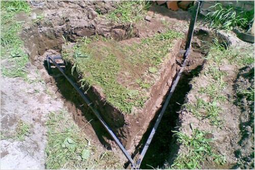
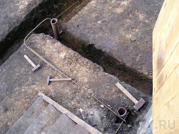
The assembly process must be started with applying the size and shape of the grounding circuit. After that, around the perimeter, a trench is digging up to 60 cm wide, so that it is convenient to carry out welding, and the depth of 80-100 cm. Earth is driven. In order for the process of entering the ground, the corners passed without problems, their ends are recommended for the cone. Before you, you do not need to score, it is necessary that the edges of the pins remain over the bottom of the trenches, approximately 20-30 cm.
Now it is necessary to dock the horizontal elements of the grounding circuit among themselves. For this, the metal tape is used. The compound is made only by electrical welding. No bolts that cover corrosion underground, and this is a partial or complete absence of contact, which will lead to the inefficiency of grounding in country house.
The next step is the connection of the circuit made with the distribution panel in the house. To do this, you can use or rod, or the same metal strip. In the yard, the connecting circuit is carried out in the trench, inside the house along the wall or plinth. At the end of the conductor, which entered the house, the bolt M6 or M8 is welded. It will be put on the ring of the wire that is responsible for the internal grounding of a private house. The mount is produced by a similar nut. You may need insulation joints.
Attention! As elements of the grounding contour, it is impossible to use metal fittings. Its outer layer is kalen, which disrupts the uniform distribution of current throughout the profile cross section. In addition, the reinforcement in the ground faster rust.
Welding places must be treated with anti-corrosion compositions. But the entire contour is painted or with some protective compositions is prohibited. Because the system requires complete contact with the ground, where wandering currents will be leaving.
On this, the installation of the grounding circuit for a private house can be considered complete. Therefore, make sure that the welding joints are durable, after which the shovels need to bury the trenches. By the way, this technology can also be used for the construction of a lightning conductor system (grossing). Here, the grounding device in a private house can be made with your own hands.
It should be noted that the correct form of grounding of a private house is an optional triangle. You can use a square, circle, line and other figures. It is important that the contour itself does not create resistance, therefore the maximum number of dried down the land of earthing and their horizontal fellow have been as much as possible. Although the triangle is a time-tested option. And one more important moment - the distance from the home contour of the grounding system to the foundation of the house should not be less than one meter.
Electric shield connection
Usually feeding private houses electric shock Performed by air lines. Therefore, entering the house is made by two wires: phase and zero. Their grounding system is based on the TN-C scheme, in which the installed zero circuit is also grounding, connected to a common neutral in a transformer substation.
Since its home is equipped with a grounding system, the connection can be carried out in two different schemes:
- TN-C on TN-C-S;
- TN-C on TT.
Connection circuit according to the TN-C-S scheme
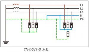
The grounding system of the private house with your own hands according to the TN-C scheme is, as a rule, a two-wire distribution in which one wire is a phase, the second zero performs two functions at once: the working conductor N and protective PE. To translate to the TN-C-S scheme, you must install an additional bus inside the distribution panel. It must have a metal contact with the electrical panel housing. It will be connected to the zero wire of the supply network and the conductor from the new grounding circuit, assembled with their own hands.
A new bus must be connected to the tire to which the N zero wire is connected coming out of the house. In this case, the N bus contact with the shield should not be. In fact, it will turn out, because a dielectric terminal terminal is installed in the shield on the tire, through which the connection is performed. By the way, the phase wire is also isolated from the elements of the camshaft and its housing.
The last stage, how to make grounding in a private house on the TN-C-S system, it is combined with a new tire and an entry circuit. Usually it uses a copper stranded cable with a cross section of at least 4 mm², one end of which is attached to the shield, the second to the bolt, welded to the end of the grounding conductor on entering the house.
Connection according to TT scheme
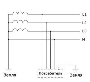
The scheme is similar to the grounding of the house on the TN-C-S system, but she has a stripping difference. In the TT connection system, the incoming PEN conductor carrying a double load (zero and ground) connects to the bus that is isolated from contact with the distribution panel. As, in principle, the phase conductor. It will be connected to the zero wire leaving home.
To the non-zoomed bus, which is not connected with other tires, the ground wire is connected, leaving home. This is also connected and the grounding comes from the street contour of the ground. The connection is made by copper cable with minimum cross section 10 mm². That is, it turns out that all the wires pass along different contours and are connected to each other only in household appliances.
A distinctive feature of the grounding system TT, its positive side is the separation of two contours: zero and grounding. In the TN-C-S system there is one negative moment - when the PEN wire is heated, electricity will go on the smallest resistance, that is, by itself protective grounding. And this is fraught with big trouble. The minimum that it may happen, there will be a short circuit in the wiring, household appliances can burn. Maximum - here and before the fire is not so far.
Grounding in a private house on the TT system guarantees complete safety with any non-standard situations. And even if the conductor Pen is corrupt, it is simply an electricity in the house, because the grounding network passes with a separate contour. And she is not connected with zero. Therefore, choosing a grounding system for the TT home (with your own hands mounted), you can be confident in its full safety.
Checking grounding
Grounding B. wooden house or brick is ready, you need to check it out. What do I need to do?
- We disassemble any socket in the house.
- We take a multimeter and exhibit it into voltage mode.
- Connect the appliances of the phase and zero device. The voltage in the network should appear.
- Then the phase and grounding are connected. The device must show a slightly different (reduced) voltage value than in the previous paragraph.
All this can be done with the help light. All the same manipulations, in which the light should burn brightly when the phase is connected to zero, and dim when the phase is connected to the ground. This is how you can answer the question how to check the ground in a private house.
In connection with the grounding device of the house with their own hands, private household owners and newly minted developers often face some problems that can not solve themselves. For example, grounding in a private house with your own hands (380V input voltage). Are there any features in making installation? There are no features, because the three-phase connection inside the house is divided by single-phase contours, which are evenly scattered throughout the building. For example, one phase goes to lighting, the second on the sockets, the third closes, for example, on a boiler. To ground the house has one contour. That is, the ground wire coming out from the house connects to the bus where the grounding from the street was connected. In this case, indoors the grounding circuit connects all sockets and powerful household appliances, as separate consumers.
Is it possible to make grounding in the house using a basement or cellar for this? There are no problems here. The main thing is that grounding in the basement (cellar) is completely in the ground so that the structure resistance is minimal. At the same time, the cellar will be an ideal place (wet floor and soil, well conductive current), the only requirement to it is to close the installation location of the contour with protective devices, for example, lay wooden grids to the floor.
Conclusion on the topic
By installing grounding scheme in a private house with your own 220V hands, it is necessary to realize that this is a safety measure. And whatever costs do not have to do, you should not worry that family budget Carries losses. It will pay off by a hundredfold, because health and life is more expensive. Therefore, it is not necessary to think, to make grounding in a private house or not. The answer is positive - you need to do a ground, without postponing. For the grounding should not be missed, but how it is done, described in detail.
If you have found a mistake, please select the text fragment and click Ctrl + Enter..
The main role of grounding is safety. Building an effective protection system for electric shock is impossible without grounding system. Even in itself grounding the metal case reduces the tension of the touch in disruption inside the equipment. And for greater reliability, a protective disconnection device is applied (so-called. UDO), which turns off the electrical appliances in disruption of insulation and occurrence hazardous tension on their buildings. And the efficiency of the UCO is largely depends on the quality of the grounding system. How to do it and how it all works, I tried to describe in this article.
TN-C-S system
In system TN-C-S from plug-free neutral Substations before entering the building passes wire Pen. combining the zero functions ( N. ) and protective ( PE ) Wires. When entering, it is divided into two wires: PE and N. . The first of them plays the role of a protective (grounding), the second - working zero wire.
TT system
In system TT. - All the same, but zero wire, which comes from a deaf-earth substation neutral, does not assume the function of the protective, and only performs the role of a zero working wire N. . Wire (tire) PE It is organized separately, with the help of an autonomous earthing and with N. Nowhere is connected.
So why Pue. Recommends the use of grounding system TN-C-S as the main system in our power grids? After all, this system has a very significant disadvantage: in the event of a break or cooling of the zero wire along the way from the substation to the consumer, all corps and metal structures connected to PE are immediately under dangerous, relative to the ground, voltage. And the one who comes to them, risks getting a life-threatening blow to life.
But there is also a big advantage: if the isolation is damaged or any other situation leading to the closure of the phase wire to the body, a situation similar to the short circuit is obtained. As a result, there is a high current, leading to the triggering of the automatic protection. In system TT. in this case, there will be no large current, therefore protection against KZ will not always work. Why so it turns out? Because the current flows not Pen. -prot, as in the previous case, and goes through the ground. Imagine that the resistance of the grounding 4 ohm, plus the resistance of the earthing at the substation is also not zero. In such a situation, the current will not more than 50a, which does not respond even a 10-ampere machine category C (justice for, it must be said that it will still work, but not by cut-off, but by overload, after a while). But if you take the private sector, then there is often the resistance of the earthing agent is not 4 ohms, but much more, and the currents of closure on the ground are much smaller.
Why do you need a Uzo?
Fortunately, there are such devices like Uzo. who react even to small (dozens of milliamper) current leakage for earth, so they are required in systems TT. . Egg resistance for clear work Uzo. At the 300 mA denomination should be at least 4 ohms, for 100 mA - 14 ohms, 30 mA - 47 ohms.
What happens when the protective device does not work? If this automatic machine TN-C-S The high short circuit current can cause melting wires and a fire. If defective Uzo in the TT system , on the electrical appliance housings there will be a life-threatening tension. Therefore, my advice to you: approach the choice of protection devices with maximum responsibility, periodically check their performance during operation, apply duplication. For example, in addition to the total, put on the outgoing lines. additional Uzo or Diffattomati At least on those lines where the greatest danger (bathroom, kitchen, etc.). In general, I will develop the rules, I would introduce a mandatory two-stage differential protection.
Now to the question about whether it is worth putting Uzo in the TN-C-S system . Definitely worth it. Of course, from the zero wire cliff described above, it will not save, but when current leakage on Earth, it will work and prevents further malfunctioning early stageWhen its value is not enough to trigger the machine.
Measures to prevent the destruction of Pen
What measures is undertaken Pue. By preventing destruction Pen. ? First of all, mechanical protection must be provided , and if the break is not avoided, then that it was not a zero wire, but the entire cable. That is, if it aerial linethen lead it straight Sipohm, split wires on the supports for TN-C-S are unsuitable. For the bucket or dump truck hooked the bucket, and the null wire is usually the bottom goes and it is much more often cling, and a tree can fall, the tractor to enter the post, strong wind, icing ... - Well, then the consequences that we have already mentioned above . In addition to gain and combined into a common shell, the zero wire is periodically re-grounded, every 200 meters for areas with low thunderstorm activity, and every 100 meters for districts with the number of thunder hours over 40 per year. And also, when applying TN-C-S mandatory condition is the potential equalization system ( Soup, DSUP ). This means that all metal (pipes, fittings, bath, etc.) are connected to the wire PE . And even in the case of a break of zero on all metal structures in the house there will be, albeit different from the ground, but everywhere the same, potential. And in private homes, in which there is a nursery, surviving buildings, etc., often SOUP It is not possible to organize, then it should be unambiguously done TT. .
Does your ground when connecting to the system TN-C-S ? There will be no superfluous. Moreover, the better grounding, the larger the current can flow. This must be taken into account when choosing a cross section of the wire from the shield to the earthinger, as well as from the support to the shield (which, by the way, there can be less than 16 square meters from any dedicated power).
What is the potential equalization system
Now O. SOUP - potential equalization system. Various engineering communications are suitable for the house: water supply, gas, sewage, etc. In the event of a malfunction in the power grid (at least the same notorious isolation of zero or, for example, the test of insulation on the body of any electrical appliance, it is possible to appear a hazardous potential difference (i.e. voltages) between the PE bus (i.e., electrical appliance cases) and Pipes or other metal structures that have contact with them. That this does not happen, all stationary metal structures (pipes, fittings, baths, sinks, pallets, door frames, etc.) are connected to the grounding system with sufficient cross-section. At the same time, before grounding the gas pipe, you need to perform a number of requirements and coordinate with the relevant service.
Besides SOUP , often occurs such a thing as DSUP - Additional system of equalizing potentials. This applies to the bathrooms and other rooms where water and electricity are adjacent. That is, an indoor with an increased humidity is put a box with a terminal box, called the potential equalization box ( COO ), from which grounding conductors are bred to all metal designs. By the way, if plastic pipes, special metal inserts are made, which are also connected to the system DSUP . Also, if there is a system of electrical heating in the floor, or wiring passes, then a grid of reinforcement is laid between them and the floor coating, which is also connected to DSUP . Fixtures for joining grounding to something there are a great set, for all cases, some of them are prefeimal in the photo below:
By the way, it is impossible to use SOUP In a separate apartment of a multi-factor house. This is fraught with severe consequences. In general, this article is written mainly for owners of private houseswhich have to take care of electrical safety yourself. Apartments are a separate question, here much depends on when the house was built when it was overhauled, which electrical wiring system in the house. Of course, all the nuances of this complex question Within the framework of one article, it is impossible to cover, so consulting always with a specialist in place, and trust such work only by qualified employees. For your life will enlighten your people and the people around you.
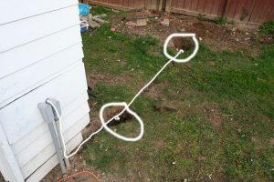
Its grounding in the private sector
Now about the grounds themselves. Usually from steel rods (corner, reinforcement, pipes), which are scored to land as much as possible. Recommendations are often found to make grounding of three pins, scored vertically located with an equilateral triangle and connected using a welding with a metal strip or reinforcement. In this case, you need to know that the closer the electrodes are located to each other, the smaller their total efficiency. If the same three electrodes arrange along one line, it will not be very worse, but even a little better. Earth efficiency is determined by spreading resistance, which is measured using special devices according to a specific technique. The lower the resistance, the better. On the network - on blogs, in forums and even on corporate sites, you can often find simplified methods for measuring ground resistance. Many of them are frankly dilettanic or very not accurate. In one of the following articles, I will focus in detail on this and explain everything in detail. In the meantime, just trust the professionals.
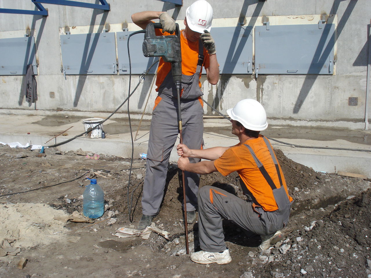
Typically, the upper layers of the soil have a high resistivity than the lower, so the entrancers are trying to drive into the ground as close as possible. For the mechanization of this process, pneumatic and electric vibrationols or jackhammers with special tips can be used. It often happens that three pins are not enough, then they do more. The distance between the pins should be quite large, it is best to two times large than their length. But you can do and single earthingIf you drive it very deeply. This design received the name of the depth-modular grounding system. How it is done, you can look at the roller below.
How to Make Ground - VideoBelow is a more low-cost ground mounting option. Here grounding electrodes are connected without threaded. According to manufacturers, a durable connection is achieved through the opening of the lower end of the pin in the nest. Of course, there are questions about how reliable and durable such contact is, but the video is quite convincing. And for fans of conservative approaches, we propose to get acquainted with the traditional method of constructing a grounding device using several electrodes interconnected by welding. Instead of reinforcement rods recommended in this video material, in case of absence, you can apply other types of metal rolled products: corners, pipes, etc. The length of the electrodes is better to take more than they are longer, the better there will be a grounding. How to measure the resistance of the grounding deviceOn this occasion, there are many misconceptions with one site on another, and transmitted from one non-electrode to another. Here is a typical example with which I categorically disagree, taken by the way, from one of the top sites (link): 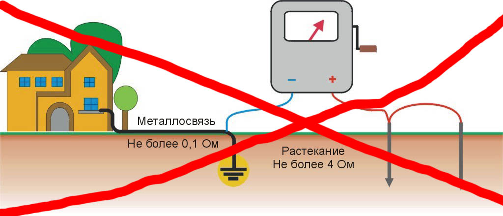 I do not even know, laugh here or cry. It is not enough that the potential and current measuring probes are connected to a loop here, so even for measurements it is proposed to use a megaometer (!). Allegedly in order to attach a high voltage to the electrodes. Yes, when measuring large resistance, these devices give hundreds and even thousands of volts. But, if there is a measuring range on such a device, allowing you to measure OM units, then no hundreds of volts will not be close. In general, nothing good from such measurements will fail. In fact, a certain amount will be measured, which includes the resistance of the wires and the resistance to spreading the grounding device and the measuring electrodes. Well, if the resistance of the wires connecting the device with electrodes, somehow can be neglected, then the resistance of the electrode-land is usually much higher than the resistance of the ground-earth, which makes the error much of the greatestly measured value. By the way, even in Wikipedia itself there are large shoals associated with the misunderstanding of the process of spreading currents in the ground and the concept of grounding resistance. Below I will write about it, but first a little about how to do it right. First, it is not necessary to invent anything, but to use specially designed instruments and techniques. Competently and intelligently it is painted and looks like this: 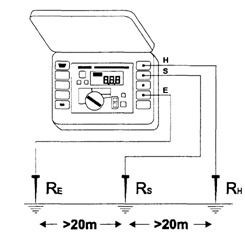 There is a very legitimate way to measure the resistance to spreading and without a special instrument. To do this, we will need a downgrade transformer 220/12 or 220/6 with a capacity of 250 W or higher. Also perfect for this and welding transformer. In addition to the transformer, you also need an ammeter and a voltmeter, the denominations of which any electrician can calculate, based on the voltage value and the expected resistance. The distances between the earthing and the potential electrode P, as well as between P and the current electrode T usually take about 20 meters. Sometimes, to limit the current, consistently with the primary or secondary winding include a ballast resistor (not shown in the diagram):  Well, finally, for advanced readers, about Jama Wikipedia. There is there such a page http://ru.wikipedia.org/wiki/Dext. And here there is such a masterpiece: Since the resistance of the grounding contour of the local memory is taken to calculate the parameters of the electrical installation of the consumer (to reduce the likelihood of creating a hazardous step voltage in the consumer, the minimum possible numerical value is usually required), then it does not take into account soil resistance between power supplies by a transformer and local consumer - The result of the resistance of the local memory of a separate consumer is taken only for a separate consumer, and not entirely power grid. In other words: since the open metal parts of the separately taken consumer are not connected directly with the transformer (and only through the main tire of the ground), then in the case of a PEN conductor break between the consumer's memory and the transformer substation is formed huge electrical resistance through the soil between themwhich according to the law of Ohm does not allow to proceed with large currents through the memory of a separate consumer. I allocated the places. In fact, there is no "huge resistance" at the soil. At the disposal of the current flowing in the ground, the entire planet. And its resistance is so small that it can not affect the value of this current. In this case, it matters only the transition resistance between the grounding device and the soil, and resistivity Soil in close proximity to the grounding device. This is what we call the impedance to spread the current of the grounding device or, in short, ground resistance. Yes, of course, the resistance of the zero wire between the substation and the consumer, usually much less than the amount of resistance to spreading substation and consumer earthing. But this resistance in several ohms or dozen ohms to be called huge somehow the language does not turn. So it turns out that even the authorities can not always be trusted. Trust but verify. And if suddenly the doubt can not be resolved - welcome to us on forum Electricians, we will solve the issue collectively. How to calculate groundingThe grounding resistance is highly dependent on the soil in which it is located. Moreover, the earthing driver scored in the ground is often located simultaneously in different layers of soil, which have different specific resistances, which complicates the calculation and the rather approximate results are obtained. Nevertheless, such calculations exist, and they are mandatory for most industrial facilities. In the private sector, a certain minimum design is usually made, resistance is measured, and then it is enhanced by the need (the earthinger drives deeper, or new grounding electrodes are added). The formula is given below to calculate a single vertical entry in a homogeneous soil: R \u003d (ρ / 2πl) (Ln (2L / D) + 0.5LN ((4T + L) / (4T-L))) ρ eq. - Specific soil resistance, Ohm * m L -
rod length in meters d. -
rod diameter in millimeters T - distance from the surface of the Earth to the middle of the rod, m When creating a multi-terrorium grounding system, it is necessary to remember that the connecting band (trumpet, fittings, corner, etc.) between the electrodes, if it is in the ground, is also an additional earthing and reduces the overall resistance. Also, the effectiveness of additional electrodes is reduced by reducing the distance between them. When the grounding device and its operation should also be guided regulatory documents: PTEEP (ch. 2.7. Grounding devices) and electrical testing standards, ch. 26, grounding devices For those who are interested, where such names are taken from, like TT, TN-C-S, etc. - It is all written in GOST R 50571.1-2009, here I will give only a small decoding:
The second letter denotes the state of open conductive parts relative to the Earth:
Subsequent after n letters denote alignment in one conductor or separation of functions for zero working and zero protective conductors:
|
Made by their own hands the contour of the grounding in a private house is one of the most important elements Power supply systems. First of all, it is necessary in terms of the safety of residents who use electrical appliances. Ground contour provides fire safety and effective work Household electrical equipment.
Install the ground contour
The main elements of the contour
- three vertical entries are driven into the ground; It can be a steel corner of 50x50x5 mm;
- three horizontal earthingers combine vertical; This is a steel strip 40x4 mm;
- the conductor between the distribution shield and the contour is steel lived with a cross section of 8-10 mm.
The armature for assembling the grounding circuit is prohibited for use, since the calene surface does not evenly distribute the current and is quickly oxidized.
The classic outline of the contour is a chain triangle placed at a distance of 1-3 meters from the foundation of the private house.
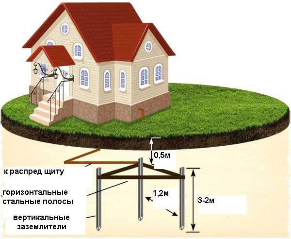
Classic ground contour form
The trench is rotated with a depth of 90 cm for laying horizontal elements, vertical pins are drunk at the corners to a depth of up to 2-3 m, leaving on the surface 25-30 cm. Welding around the perimeter welded the steel strip, connecting vertical pins, then rod 8-10 mm from contour to the camshaft housing.
The steel casing was fastened to the body of the distribution shield, for this end, it is necessary to break off and drill a hole under the bolt. The connection site is carefully cleaned for reliable electrical contact. You can pave a steel strip from the contour to the shield, the cross-sectional area of \u200b\u200bthis conductor should be at least 16 kV / mm.
It is believed that the flat steel tire is more efficient, it has a large square of contact with the soil, the best conductivity of the current. The complexity of using such a strip is when turning in the process of laying into the ground and laying along the foundation and walls of the house. You have to cut the bus into pieces and weld under the desired angle.
Connections of contour structures, horizontal and vertical elements are performed only by welding. It is prohibited to twist bolts, the contacts are quickly oxidized, the contour ceases to perform its functions. It is strictly forbidden to paint the details of the underground part of the contour, the paint is an insulator and prevents the passage of currents into the ground.
If there are problems with the performance of welding in the country or in a country private house, bolted contour elements can be allowed. Then they definitely remain over the surface of the soil, the contacts are carefully cleaned, the bolts are reliably tightened. The connection location periodically is to lubricate the conductive lubricant.
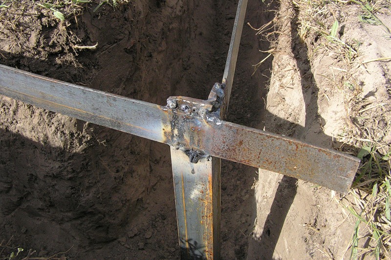
Welding design
Grounding industrial manufacture
Some companies produce ground circuit sets for the 220V and 380V network from galvanized and copper steel elements. The design of such grounding goes to a depth of 6 m, the vertical pin of four components is connected by couplings with carvings. At the end, a pointed tip screws.
For easier penetration of the galvanized pin into the ground, it is recommended to pre-make the holes of the brown. On the surface it is left 20-25 cm pin, a brass clamp is mounted on this site.
From the housing of the camshaft in the house before the grip clip, an isolated copper or galvanized stranded wire is in isolation. The threaded connection on the bolts is lubricated to the conductive paint.
Such kits serve at least 25 years, have good conductivity, simply mounted. As a deficiency, the cost can be noted. Approximately 3-5 thousand rubles, not everyone can allow such costs, having the opportunity to use cheaper materials, but no less effective.
Grounding device
How to make grounding with old wiring
The most correct solution will be in replacing the old wiring to a new one, where there are four wires in cables. One of the yellow-green wires is designed for grounding. All this can be done with your own hands; The complexity is that it will take time, you will have to spend financial resources.
Practically the wiring scheme in the country or in the house will be significantly changed. Before doing this, it is worth being ready for overhaul. Sockets, switches, junction boxes can be left on old places in the house or in the country, if necessary, the location scheme can be changed.
By installing new sockets correctly, it is necessary to trace all the grounding wires to connect in junction boxes, and in the distribution shield it went onto the grounding bus. Grounding tires are attached to the housing of the shield. Having reliable electrical contact, the wire or plate is on the contour. Following the instructions above, you can make grounding for all the rules.
A cheaper way to make a correct grounding in the country or in the house - turn off the old wiring from the switchboard and leave it stamped in the walls. A new scheme is laid outside in plastic cable-channels, while you can use new sockets and switches by installing them in older pealations.
Distribution boxes can be used already installed, clearing them from old wires. In the presence of funds, you can immediately buy all items for the outer wiring: junction boxes, sockets, switches, cable channels, wires and collect a new scheme.
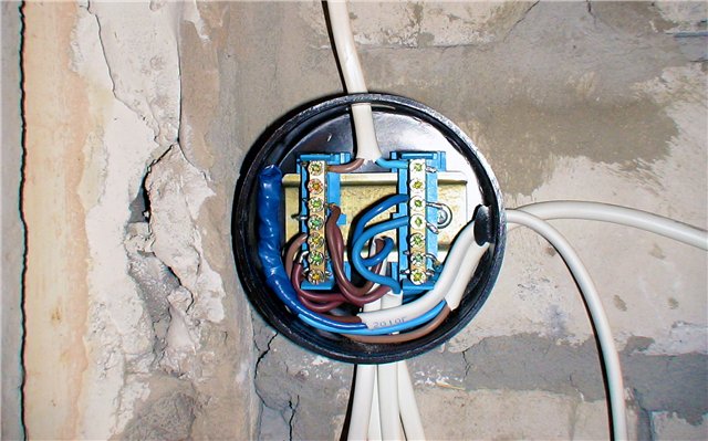
Installing a junction box
By installing modern electrical equipment in the old house with grounding elements, it is enough to make a ground loop, mount a new distribution shield. Leaving the old wiring for low-power devices, for a split-system, a heating boiler, a washing machine, an air conditioner is worth making a separate wiring through the cable channels, taking into account grounding. At the same time, you will have to spend only on the shield, automatic protection, several sockets and cable channels.
Not everyone by pocket to spend overhauxal overhaul with a replacement of wiring on the cottage or country house. Even if someone decides to do everything with their own hands, you will need money anyway. The easiest and cheapest way when the wiring scheme is complemented by one ground wire, and the remaining wires remain in old places.
In order not to stick the walls, the ground wire can be carefully put in plastic cable channels. They fit well into any interior of the house and cottages, just attach to the walls of any material.
This is an easy task: fasten the cable channels from the switchboard between the boxes, from the boxes to the sockets. In junction boxes, all ground wires are connected to each other and overlook the turbulent shield.
Ground. Video
How to make grounding in a private house schematically tells this video. Only the knowledge of the process itself can prevent errors directly during the work.
We looked at several options, how can I make a right ground for networks at 220 and 380V in a private house or in the country. Each owner, based on the specified conditions, given its financial capabilities, makes a decision himself. Of course, there is always a choice which option to use to properly assemble the grounding scheme.
In order to security the owners prefer to make grounding in a private house at the stage of design of the building. This protection method will help to avoid negative consequences as a result of a sharp voltage jump in electrical network by 220 volts. The article will talk about how to make grounding in a private house, about his kinds, installation sequences and recommendations for work.
In order to make grounding in a private house with your own hands, you need to decide on what kind of protective circuit must be installed in a particular case. Ground contour has two types: working and protective.
The working type of grounding allows to ensure reliable and proper operation of powerful industrial equipment. At home it is not advisable to apply it, as usually there is no such technique in the residential premises. More often, the earthing motors are made for an electrical network with a voltage of 380 volts.
With sharp voltage surges, the vehicle breakdown is prevented. Most electrical appliances and technology. Typically, such jumps appear with significant insulation damage in the transformer winding. Also, when you hit the house of lightning, the entire charge that will fall on the lightning message will go to the ground, and all the home electrical engineering will continue to work stably.
The protective type of grounding is based on the fact that the electrical equipment that is under the influence alternating current, purposefully connects to "Earth". This method It is recognized as the most efficient and most common. If a three-core cable is laid in the house, then there will be no problems with.
Scheme of grounding of grounding
Last, protective contour Grounding, has many different installation schemes. Often it is applied to an electrical network with a voltage of 220V. If the installation and installation is done correctly, but the effective protection of the house from the excess voltage for a long time will be ensured. To do this, it is enough to make the connection of "land" in the outlet, and a reliable structure with a low resistance, which is placed under the ground.
There is a separate list of household appliances and devices, which are highly recommended to ground with any of these methods: a boiler, a system block of a computer, a microwave, washing machine and an electric oven.
Earth loop and lightning
The grounding circuit is a three-in-room cable wire that connects electrical appliances from the ground. With such a connection, most negative processes in the technique (open phases or short circuits) who create a wandering current will be directed towards grounding construction, and then to the ground. The circuit of the grounding contour is quite simple, and it can be done with your own hands, if you adhere to certain rules.
The circuit of the protective circuit of the grounding provides for each outlet of the "Earth" wire, which will reach the ground design. When connecting household appliances or electrical engineering to the network, they will also be connected to the ground terminal. All wires must be approached by the distribution panel, and a separate cable will be assigned from it. On the one hand, grounding wires from a residential building or premises will be connected to it, and on the other - the grounding structure that will go to a certain depth in the ground.
Also, a lightning conduction can be attached to the grounding circuit. Lightning reception will allow you to take a powerful charge of lightning and translate it through the current in the ground. If grounding elements have already been made in the house, then additional installation protective device From lightning it will be easier. An effective device for taking the charge of the zipper must consist of such a kit: lightningness, a cocoquer and grounding design.
If before the house did not have a protective circuit, then all these elements need to be installed. But when the current and the element connecting with the Earth is all the home network, it is enough to install only a lightning conductor. This device is placed significantly higher than the most high Point At home to take a blow. This protective system can be made with your own hands. It doesn't matter how an outwardly lightning track will look like, but its core must be a hollow. This is necessary in order for the conductor to connect to the grounding circuit.
Also, the lightning conduction can be made on the site as a separate tower. Its spire will rise 2-3 meters above the maximum point of the residential building, providing reliable protection against lightning strike. At the same time, the ground protective contour can be both joint and separate (more costly).
Video "Grounding Installation"
Ground installation stages
If you wish to make a grounding of the house itself, first of all you need to get some knowledge of electrical engineering. Specialists strongly recommend using ready-made ground mounting schemes. It is desirable before starting work to familiarize yourself with the rules of the electrical installation device (PUE).
Then it is necessary to have a grounding structure to work, which will be placed under the ground. You can purchase a ready-made reliable and certified kit. For example, there is a kit EZ 15, EZ 38 or EZ 48 (marking determines which kit is needed for the corresponding type of soil). If you wish, you can make a similar design by itself using a similar scheme.
Then you need to determine which system there will be a grounding contour in a residential building. The most common system is TT. The labeling of the TT system means that the neutral is deaf-earth, and its open conductors are grounded regardless of the relationship to the "earth" of neutral power supplies or other power points. For the TT system, it is characterized by grounding at the bottom of the house.

You can make grounding on the TT system with your own hands if it is properly followed by its scheme. The TT system is distributed in the villages, they connect small houses and buildings, cabins and sheds. Usually the TT system is used when powering electrical installation up to 1000 volts, and if there is no possibility to follow the conditions of the TN system. For TT, it is necessary to connect the protective shutdown device. One of the most important deficiencies of the TT system is the simultaneous refusal of the UZO and the phase breakdown on the housing of the grounded electrical instrument.
Further, you need a suitable tool. We need a set of wrench, portable welding machine, grinding machine, heavy sledgehammer, bayonet shovel, screwdriver kit. Using the tool you need to make grounding design. You can stay at an embodiment with a triangle form.
At a sufficient distance from the house you can draw an equilateral triangle with a distance between the vertices of 1.5 meters. At this place, pull out the pit depth to 1 meter. In places of vertices, steel fittings are clogged with round cross section Long in 2-3 meters and a thickness of at least 35 mm. Then the upper parts of the reinforcement must be combined with a metal bus 4 cm wide and a thickness of 4 mm.
To do this, cut a set of blanks with a length of 1.6-1.7 meters (with a stock). For proper installation Tire length electrodes is enough to connect them to each other. When fastened, welding uses. Connecting wire, which will be connected to the "Earth" wire near the distribution panel, it is desirable to choose with a copper section. Then the trench is riveted.
Then you can proceed to connect all sockets in the house to the "Earth", which is located in a three-core power cable. You need to work with de-energized wiring. When you were convinced that you had a connection correctly, you can proceed to the control check.
What is prohibited according to the standards
![]()
It is very important that when installing the grounding, the technology of connecting and the rules for placing electrical installations were observed. If necessary, with your own hands in the house, which has a power supply with a voltage of 220 volts, is quite simple. To do this, follow the existing PUE standards. The rules of the electrical installation device provide that when installing the circuit cannot be connected or twisting the stripped wires of the wires outside. If there is direct access to such contacts, then negative consequences may arise. At high voltages on the network, this zone may be a serious threat to a person's life.
It is forbidden to use in the ground design of the main elements that are covered with paint or other coatings (except for the oxidized metal layer), including an oxide film. It is impossible to make grounding of electrical household appliances on gas and heating pipes, as well as on the water supply. It is forbidden to make a serial connection when installing. PUE standards are also provided that reinforced concrete structures with metal parts that are under voltage cannot be used as grounding contours. It is also forbidden to use pipes for various purposes with combustible and easily flammable substances.
Control check
To make sure that the grounding circuit is made correctly, you need to measure the resistance value at a distance of 12-15 meters. Be sure to correctly distribute the polarity between the connected contacts to the earthing ("-") and a set of measuring electrodes ("+"). There is a distance of 1.5 m between the electrodes. If the resistance value is less than 4 ohms, then everything is done correctly. If the resistance is higher, then you need to find and fix the problem.
Video "Make a grounding in the house yourself"
This video material contains a visual manual that will allow you to independently make such an operation as the grounding organization. The kit also includes a contour construction manual.
1539 Views.


